EP1514068B1 - Rückstossbeherrschungsvorrichtung - Google Patents
Rückstossbeherrschungsvorrichtung Download PDFInfo
- Publication number
- EP1514068B1 EP1514068B1 EP03729754.6A EP03729754A EP1514068B1 EP 1514068 B1 EP1514068 B1 EP 1514068B1 EP 03729754 A EP03729754 A EP 03729754A EP 1514068 B1 EP1514068 B1 EP 1514068B1
- Authority
- EP
- European Patent Office
- Prior art keywords
- slider
- bolt head
- barrel
- firearm
- recoil
- Prior art date
- Legal status (The legal status is an assumption and is not a legal conclusion. Google has not performed a legal analysis and makes no representation as to the accuracy of the status listed.)
- Expired - Lifetime
Links
- 238000010304 firing Methods 0.000 claims description 67
- 230000007246 mechanism Effects 0.000 claims description 58
- 230000004044 response Effects 0.000 claims description 14
- 238000012546 transfer Methods 0.000 claims description 11
- 238000011084 recovery Methods 0.000 claims description 3
- 238000006243 chemical reaction Methods 0.000 claims description 2
- 238000013461 design Methods 0.000 description 27
- 230000009471 action Effects 0.000 description 26
- 230000009467 reduction Effects 0.000 description 15
- 210000003414 extremity Anatomy 0.000 description 14
- 238000006073 displacement reaction Methods 0.000 description 12
- 238000009527 percussion Methods 0.000 description 12
- 238000013519 translation Methods 0.000 description 12
- 230000000694 effects Effects 0.000 description 11
- 238000000034 method Methods 0.000 description 10
- 230000008901 benefit Effects 0.000 description 7
- 230000006870 function Effects 0.000 description 5
- 230000006872 improvement Effects 0.000 description 5
- 230000002411 adverse Effects 0.000 description 4
- 238000013459 approach Methods 0.000 description 4
- 238000002347 injection Methods 0.000 description 4
- 239000007924 injection Substances 0.000 description 4
- 230000009172 bursting Effects 0.000 description 3
- 238000004140 cleaning Methods 0.000 description 3
- 230000004048 modification Effects 0.000 description 3
- 238000012986 modification Methods 0.000 description 3
- 230000010355 oscillation Effects 0.000 description 3
- 230000000295 complement effect Effects 0.000 description 2
- 230000006835 compression Effects 0.000 description 2
- 238000007906 compression Methods 0.000 description 2
- 238000010276 construction Methods 0.000 description 2
- 125000004122 cyclic group Chemical group 0.000 description 2
- 238000009826 distribution Methods 0.000 description 2
- 238000005516 engineering process Methods 0.000 description 2
- 239000000284 extract Substances 0.000 description 2
- 210000000245 forearm Anatomy 0.000 description 2
- 239000004519 grease Substances 0.000 description 2
- 238000012423 maintenance Methods 0.000 description 2
- 238000004519 manufacturing process Methods 0.000 description 2
- 238000012360 testing method Methods 0.000 description 2
- 210000000707 wrist Anatomy 0.000 description 2
- 206010006356 Breech presentation Diseases 0.000 description 1
- 238000010521 absorption reaction Methods 0.000 description 1
- 239000000969 carrier Substances 0.000 description 1
- 239000000356 contaminant Substances 0.000 description 1
- 238000007796 conventional method Methods 0.000 description 1
- 230000036461 convulsion Effects 0.000 description 1
- 230000001351 cycling effect Effects 0.000 description 1
- 230000003247 decreasing effect Effects 0.000 description 1
- 230000007812 deficiency Effects 0.000 description 1
- 230000003111 delayed effect Effects 0.000 description 1
- 230000001627 detrimental effect Effects 0.000 description 1
- 230000003467 diminishing effect Effects 0.000 description 1
- 230000008030 elimination Effects 0.000 description 1
- 238000003379 elimination reaction Methods 0.000 description 1
- 230000007613 environmental effect Effects 0.000 description 1
- 239000002360 explosive Substances 0.000 description 1
- 210000003811 finger Anatomy 0.000 description 1
- 210000004247 hand Anatomy 0.000 description 1
- 238000007373 indentation Methods 0.000 description 1
- 230000010354 integration Effects 0.000 description 1
- 230000010534 mechanism of action Effects 0.000 description 1
- 239000002184 metal Substances 0.000 description 1
- 230000008520 organization Effects 0.000 description 1
- 239000000843 powder Substances 0.000 description 1
- 239000003380 propellant Substances 0.000 description 1
- 230000000284 resting effect Effects 0.000 description 1
- 239000000523 sample Substances 0.000 description 1
- 239000004576 sand Substances 0.000 description 1
- 230000009291 secondary effect Effects 0.000 description 1
- 239000000243 solution Substances 0.000 description 1
- 230000008685 targeting Effects 0.000 description 1
- 210000003813 thumb Anatomy 0.000 description 1
- 210000001364 upper extremity Anatomy 0.000 description 1
- XLYOFNOQVPJJNP-UHFFFAOYSA-N water Substances O XLYOFNOQVPJJNP-UHFFFAOYSA-N 0.000 description 1
Images







Classifications
-
- F—MECHANICAL ENGINEERING; LIGHTING; HEATING; WEAPONS; BLASTING
- F41—WEAPONS
- F41A—FUNCTIONAL FEATURES OR DETAILS COMMON TO BOTH SMALLARMS AND ORDNANCE, e.g. CANNONS; MOUNTINGS FOR SMALLARMS OR ORDNANCE
- F41A3/00—Breech mechanisms, e.g. locks
- F41A3/02—Block action, i.e. the main breech opening movement being transverse to the barrel axis
- F41A3/04—Block action, i.e. the main breech opening movement being transverse to the barrel axis with pivoting breech-block
-
- F—MECHANICAL ENGINEERING; LIGHTING; HEATING; WEAPONS; BLASTING
- F41—WEAPONS
- F41A—FUNCTIONAL FEATURES OR DETAILS COMMON TO BOTH SMALLARMS AND ORDNANCE, e.g. CANNONS; MOUNTINGS FOR SMALLARMS OR ORDNANCE
- F41A25/00—Gun mountings permitting recoil or return to battery, e.g. gun cradles; Barrel buffers or brakes
- F41A25/10—Spring-operated systems
-
- F—MECHANICAL ENGINEERING; LIGHTING; HEATING; WEAPONS; BLASTING
- F41—WEAPONS
- F41A—FUNCTIONAL FEATURES OR DETAILS COMMON TO BOTH SMALLARMS AND ORDNANCE, e.g. CANNONS; MOUNTINGS FOR SMALLARMS OR ORDNANCE
- F41A3/00—Breech mechanisms, e.g. locks
- F41A3/12—Bolt action, i.e. the main breech opening movement being parallel to the barrel axis
- F41A3/54—Bolt locks of the unlocked type, i.e. being inertia operated
- F41A3/56—Bolt locks of the unlocked type, i.e. being inertia operated the bolt being provided with an additional slidable mass
-
- F—MECHANICAL ENGINEERING; LIGHTING; HEATING; WEAPONS; BLASTING
- F41—WEAPONS
- F41A—FUNCTIONAL FEATURES OR DETAILS COMMON TO BOTH SMALLARMS AND ORDNANCE, e.g. CANNONS; MOUNTINGS FOR SMALLARMS OR ORDNANCE
- F41A3/00—Breech mechanisms, e.g. locks
- F41A3/64—Mounting of breech-blocks; Accessories for breech-blocks or breech-block mountings
- F41A3/78—Bolt buffer or recuperator means
- F41A3/82—Coil spring buffers
- F41A3/84—Coil spring buffers mounted within the gun stock
-
- F—MECHANICAL ENGINEERING; LIGHTING; HEATING; WEAPONS; BLASTING
- F41—WEAPONS
- F41A—FUNCTIONAL FEATURES OR DETAILS COMMON TO BOTH SMALLARMS AND ORDNANCE, e.g. CANNONS; MOUNTINGS FOR SMALLARMS OR ORDNANCE
- F41A5/00—Mechanisms or systems operated by propellant charge energy for automatically opening the lock
- F41A5/02—Mechanisms or systems operated by propellant charge energy for automatically opening the lock recoil-operated
- F41A5/10—Mechanisms or systems operated by propellant charge energy for automatically opening the lock recoil-operated having a movable inertia weight, e.g. for storing energy
- F41A5/12—Mechanisms or systems operated by propellant charge energy for automatically opening the lock recoil-operated having a movable inertia weight, e.g. for storing energy mounted in a gun having a fixed barrel
Definitions
- This invention relates to small and heavy caliber firearms and cannons as well as to improved methods and devices for reducing the consequences of recoil and improving performance in firearms and cannons.
- the device relates to the control or management of the recoil forces for small caliber semiautomatic or automatic firearms.
- Hiram Maxim was the first to use recoil forces to mechanize the ejection and loading actions in a machine gun, Browning put the muzzle blast to effective use, and Bergman devised the simple blowback action.
- the three basic ways of obtaining an automatic operation were developed from the use of recoil, gas, or blowback actuation.
- Later applications of the blowback operation used either simple blowback or assisted blowback, with or without locked, delayed, hesitation or retarded blowback, and even blowback with advance primer ignition.
- Gas operation lead to the use of long and short-stroke pistons and even, in more modem weapons, direct gas action, where the derived gas directly activates a bolt carrier in which an adequate recess is managed.
- Recoil operation traditionally provided the locking mechanism of the bolt to the barrel so that they can slide together under the thrust of the pressure when firing, either under a short or long recoil operation and with or without muzzle boosters or recoil intensifiers.
- the mechanisms found on current firearms although reliable and widely employed, nevertheless suffer from a number of deficiencies.
- some mechanisms increase the length of the housing of the breech, resulting in interior clutter and increased weight.
- the amplitude of recoil is relatively critical due to its effect on accuracy, and the existing mechanisms fail to provide a satisfactory or optimum reduction in recoil, which permits the resulting upward movement of the barrel.
- the direction of the recoil forces generally coincides with the longitudinal axis of the gun barrel.
- the gun barrel is generally located above the shoulder in a person firing a rifle or above the hand in a handgun, and more precisely above the gap between the thumb and index finger of a person firing a handgun.
- this invention provides new solutions, mechanisms, and systems for operating the firing action of a firearm and allows revolutionary changes in the ergonomics applicable to firearm design and use.
- the present approach is new and innovative.
- the invention is aimed at addressing the design of a new firearm by taking advantage of available energy to help operate the firearm and consequently minimize and/or compensate for the adverse effects and improve control.
- a first innovation is the deliberate use and control of energy to address all the adverse effects during operation. This allows one to conceive of a new firearm design and organization, still dependable, but vastly improved. This new approach also allows a firearm designer to address concerns and constraints as part of a whole rather than as individual problems, so as to take into account the advantages and interfaces between firearm components during operation. Considering the operation as a whole, as this invention exemplifies, allows completely new concepts and expands the universe of designs, configurations, and mechanisms possible for firearms.
- US 1 464 864 discloses a firearm with an inertia block adapted to reciprocate back and forth in a receiver.
- the firearm further comprises breech bolt which is movable together with the inertia block and linked thereto by a hook.
- the present invention is defined by the claims and addresses the problems and disadvantages associated with conventional firearms and weapon systems and provides improved devices for reducing recoil effects in a variety of firearms, cannons, and systems.
- one aspect of the invention is to reduce the amplitude or consequences of recoil and/or eliminate, for all practical purposes, the weapon's reactive upward jerking.
- the invention also facilitates the design and production of a more compact weapon and/or allows substantial reductions in the weight of the frame, which results in many new design possibilities and improvements in ergonomics.
- incorporating one or more of the many aspects of the invention into a firearm improves accuracy and/or reduces the total weight.
- One of the fundamental principles of the present invention is the transfer of mechanical recoil forces to a direction outside of the longitudinal axis of the gun barrel. As can be seen in each of the exemplary embodiments disclosed herein, the transfer of forces disperses or dissipates recoil forces and thereby reduces the moment responsible for the upward jerking characteristic of conventional firearms.
- the portion of the recoil forces beyond those used to operate the novel mechanisms or system of the invention is transferred in a direction outside the longitudinal axis of the barrel and effectively disposed of, thereby significantly reducing or even eliminating the component of recoil forces along the longitudinal axis of the barrel that is responsible for the reactive jerking of the weapon when fired.
- the embodiments disclosed herein are exemplary and that one or more of the foregoing principles can be applied in many variations to firearms of various calibers and applications.
- the mechanism that transfers forces can be oriented to counteract the recoil forces along the longitudinal axis of the gun barrel to effectively eliminate or compensate for the upward jerking of the weapon.
- the invention comprises a mobile breech made up of articulated parts including an inertia block and a bolt head.
- the action of the mobile breech is unconventional in that it causes the inertia block to alternate out of and into alignment with the longitudinal axis of the barrel. This is contrary to the action of conventional mechanisms in which the parts that compose a mobile breech move in translation along the longitudinal axis of the barrel.
- the present invention transfers the recoil forces generated by firing to the inertia block, M, by means of a bolt head, m, moving backward at an initial velocity, v i .
- this transfer of recoil forces from the bolt head to the inertia block is preferably made using corresponding angled surfaces of the bolt head and the inertia block.
- An impulse transferred to the inertia block translates to a force in a direction other than along the longitudinal axis of the gun barrel thanks first to the configuration of the contact surfaces, and second to the articulated parts connecting to the inertia block, and third the path that guides the movement of the inertia block.
- the inertia block is thus imparted with a momentum, Mv M , and the velocity vector, v M , has a component parallel to the longitudinal axis of the gun barrel, oriented toward the back or front of the weapon, while the other component is oriented in a lateral direction from the axis of the gun barrel, either below or above the weapon.
- the mobile breech comprises an inertia block that operates to transfer momentum or forces generated by the firing of one or more cartridges or rounds of ammunition to a direction outside of the longitudinal axis of the gun barrel.
- the inertia block is a component part of a firearm, or more particularly a mobile breech, that moves in response to the force of firing and/or moves in response to the movement of a bolt head.
- the inertia block or masses allows for the absorption of recoil forces and directs those forces in the form of momentum in a direction outside the longitudinal axis of the barrel.
- the use of the term "inertia block” can refer either to a single or to multiple parts or masses.
- the component masses of the inertia blocks may optionally serve additional functions, such as providing armor protection to or housing components for gun or cannon emplacements equipped with the present invention.
- the terms “bolt” and “bolt head” are used interchangeably.
- the bolt head In a system where the bolt head absorbs the recoil forces directly through contact with the spent casing of the cartridge, the bolt head is imparted with a rearward momentum along the longitudinal axis of the barrel.
- the bolt head impulsively strikes the inertia block, either directly or through a linkage, and the momentum of the bolt head is then transferred to the inertia block.
- the bolt head is typically of significantly smaller mass than the inertia block or blocks. Because of the relative masses of the bolt head and inertia block, the inertia block will move with a different velocity than the bolt head.
- the inertia block or blocks serve the same basic function - to absorb recoil forces and/or re-direct recoil forces out of the longitudinal axis of the barrel.
- An aspect of the present invention is the use of inertia block guides to constrain the movement that the inertia block follows to a direction other than along the longitudinal axis of the barrel, thereby transferring the recoil forces out of the axis of the gun barrel and reducing the reactive jerking described above.
- the path of the inertia block in response to the recoil impulse leaves the longitudinal axis of the gun barrel, thereby translating recoil forces out of this axis.
- Part of the space occupied by the inertia block during its back and forth trajectory can be located below the axis of the gun barrel, while the rest of the trajectory of the inertia block in its alternating action, as well as the corresponding part of the breech block, can be situated above the barrel axis.
- the inertia block can move along a path defined by its guide.
- the guide can be a slot in a part of the firearm designed to allow the inertia block to move back and forth from a loaded position to an end point of its movement.
- An inertia block guide can be configured so that the movement of the inertia block in response to the impulse can be one of pure translation or the movement can be more complex in nature.
- there can be a direct connection possible between the bolt head and the inertia block that causes the movement of the inertia block to move along its guide or there can be a simple linkage, such as pin rod, or there can be more complex linkages, such as multiple rods and/or articulated parts.
- the inertia block's movement in turn governs the movement of the bolt head and/or vice versa, due to the manner of their linkage.
- a phase displacement can be achieved by engineering the linkage between bolt head and inertia block with a slight play, for example in the longitudinal direction.
- the phase displacement can be achieved through a delay in the direct contact of the bolt head with the inertia block enabled by the shape or configuration of the contact surfaces.
- the degree of phase displacement is a matter of design option, but some phase displacement is preferred.
- the recoil moment can be further controlled or managed through the positioning of the barrel of the weapon relative to the grip or stock of the weapon.
- a conventional handgun grip can be placed behind a breech block of the present invention.
- the axis of the barrel is not found above the grip, as it is conventionally in handguns, but in front of it, typically at mid-height or at two-thirds the height of the grip.
- the gun barrel axis is in line with the forearm of the person aiming the gun and not above it, the effect of which is to eliminate the upward jerking characteristic of the recoil response of conventional guns.
- the recoil control device's components can be advantageously prepared with comparatively large parts or large diameter spindles or rods, which simplifies manufacture.
- This advantage of the present invention greatly improves the reliability in service and the resistance to jamming by sand, mud, and other environmental contaminants and simplifies cleaning and dismantling of the firearm.
- the mechanisms and aspects of the invention can be used to complement or improve existing or conventional firearms and can be combined with various arrangements, attachments, and combinations, including without limitation internal release systems, loading systems, ejection systems, gas injection systems, recoil reduction systems, muzzle brakes, sighting systems, tripods, mounting systems, and firing mechanisms.
- the invention comprises an improved and novel recoil control device for use in a firearm, such as a semiautomatic or automatic firearm, in which, for example, a bolt head is configured to alternate between a forward position and a rearward position in response to the firing of one or more cartridges; and an inertia block is connected to the bolt head such that the bolt head imparts an impulse to the inertia block as it alternates between its forward position and its rearward position, the impulse having a component, or force distribution or vectorial force component, lateral to the firing axis of the barrel of the firearm.
- a bolt head is configured to alternate between a forward position and a rearward position in response to the firing of one or more cartridges
- an inertia block is connected to the bolt head such that the bolt head imparts an impulse to the inertia block as it alternates between its forward position and its rearward position, the impulse having a component, or force distribution or vectorial force component, lateral to the firing axis of the barrel of the firearm.
- the force transferred to the inertia block can be in any one of several directions and the inertia block can therefore traverse one of a variety of paths from the impulse imparted through the bolt head, including, but not limited to: a downward sloping, straight path toward the anterior of the firearm; a curved or curvi-linear path; a path extending outward from the barrel; a path moving inward toward the barrel; and a path crossing over the barrel.
- the path chosen relates to the design characteristics of the firearm desired.
- the inertia block or mass appropriate for a particular firearm relates to the design characteristics of the firearm.
- the inertia block comprises a sloped or angled surface, or a leading sloped surface, that can be contacted by the bolt head to transmit the impulse from firing.
- the inertia block comprises a part or parts that reciprocates between two or more positions and moves in response to the impulse from the bolt head.
- the recoil control device of the present invention can be incorporated into heavy caliber firearm and cannon mechanisms.
- a heavy caliber rifle such as a vehicle-mounted rifle or portable rifle of between 50 caliber and 105 mm, or even higher as in a 155 mm cannon, can be produced with an inertia block to translate forces out of the axis of the barrel.
- the transfer of the impulse of percussion from the bolt head to the inertia block can be through direct contact between the two parts or through a simple or even a complex linkage.
- a pin connected to the bolt head moves within a slot connected to the inertia block.
- the inertia block and bolt head are designed to automatically return to their resting or chambered position.
- a variety of mechanisms can be used to move the bolt head and/or inertia block in the return path.
- a preferred embodiment employs a spring operably connected to or contacting the inertia block, which can be referred to as the return spring.
- a variety of spring types can be adapted for this purpose.
- Alternative return or recovery mechanisms can be designed by one of skill in the art.
- the recoil control device according to the invention is be manifested in Figures 8 and 27-32 accompanying this disclosure. Also, numerous embodiments and alternatives are disclosed in the accompanying claims.
- the invention provides a method for making a recoil control device of the invention and/or incorporating into a firearm a recoil control device comprising one or more inertia blocks operably connected to a bolt head, or moving in response to other forces, in order to move in a manner that directs momentum outside of the longitudinal axis of the barrel.
- the present invention advantageously reduces the consequences of recoil and/or eliminates, for all practical purposes, a weapon's reactive jerking and permits a more compact weapon for a given caliber ammunition.
- the present invention enables a lighter frame for the weapon and a more compact and therefore more stowable or containable weapon. This allows moveable weapon systems to store more ammunition per sortie. Further, this invention enables a simplified construction for the base by diminishing the recoil tendency and dampening the stress acting upon the platform as a whole.
- a force component perpendicular to or lateral to the longitudinal axis of the barrel refers to a vectorial component or part of a force or momentum vector directed outside the longitudinal axis of the barrel.
- the invention comprises a mobile breech made up of connected parts that comprise an inertia block and a bolt head.
- the action of the mobile breech is unconventional in that it causes the inertia block to alternate out of and into alignment with the longitudinal axis of the barrel. This is contrary to the action of conventional mechanisms in which the parts making up a mobile breech move in translation along the axis of the barrel.
- the present invention translates forces generated by the recoil to the inertia block, M, by means of a bolt head, m, moving backward at an initial velocity, v i , in the instant following firing.
- This transfer of recoil forces from the bolt head to the inertia block is preferably made via contact between corresponding angled surfaces of the bolt head and inertia block.
- the impulse transferred to the inertial block translates to a force in a direction other than along the axis of the gun barrel.
- the configuration of the contact surfaces allows the articulated parts to guide the inertia block.
- the inertia block is thus imparted with a momentum, Mv M , and the velocity vector, v M , has a component parallel to the axis of the gun, toward the back of the weapon, and a component perpendicular to the axis of the gun.
- Inertia block guides can be configured so that the movement of the inertia block in response to the impulse can be one of pure translation or more complex in nature.
- the inertia block's movement in turn governs the movement of the bolt head, due to the manner of their linkage.
- the present invention in particular allows two parameters to be varied: the ratio between the mass of the inertia block and the bolt head, and the angle between movement of the inertia block and the axis of the gun.
- the angles formed by parts of the mobile breech can be manipulated to optimize recoil reduction, firing rate, and other operational characteristics in a variety of firearm styles and sizes. Control or variance of such factors is not typical of present firearms technology.
- the recoil control device notably enables construction of automatic firearms of particular compactness for their caliber.
- the trajectory of the inertia block leaves the longitudinal axis of the gun barrel.
- part of the space occupied by the inertia block during its back-and-forth trajectory is located below the gun barrel, while the rest of the trajectory described by the inertia block in its alternating action, as well as the corresponding part of the breech block, is situated above the barrel axis.
- a conventional handgun grip can be placed behind a breech block of the present invention.
- the barrel is not found above the grip, as it is conventionally in handguns, but in front of it, preferably at mid-height or at two-thirds the height of the grip.
- the middle of the gun barrel axis is in line with the middle of the forearm of the person aiming the gun and not above it, the effect of which is to eliminate the upward jerking characteristic of the recoil response of conventional guns.
- the placement of the barrel relative to the height of a grip can vary, but it is preferably placed at about 5% to about 95% of the height of the grip, or about 40% to about 80%, or about 50% to about 70%, or about 60% to about 70%.
- any particular configuration of the axis of the barrel relative to the grip or stock can be selected.
- the present invention preferably uses the handgrip as part of the housing for the inertia block and return device or spring, and this arrangement substantially eliminates the upward jerking of the gun from recoil.
- the handgrip as shown in the Figures and described here, embodiments of the invention encompass heavy and light machine guns and cannons as well as handguns. Thus, handgrips are not required.
- the preferred embodiment comprises a bolt head operably linked to an inertia block so that the bolt head imparts an impulse to the inertia block upon firing the firearm.
- the inertia block can be referred to as a "slider" since it can be designed and produced as a sliding mechanism that travels in a fixed path.
- the selection of the weight, shape, and path of the slider will depend on a number of design factors, including, but not necessarily limited to: the desired placement of the barrel relative to the handgrip or stock, the part of the frame that is stabilized by a person firing the firearm, or the part of the frame connecting the firearm to a tripod or other support device; the degree of recoil reduction or counteracting of the upward jerking recoil forces desired; the barrel length; the weight of the bolt head; the weight of the firearm; the presence or absence of a muzzle brake; and, of course, the ammunition used in the firearm.
- One of skill in the art can routinely measure the recoil characteristics of any selected design in order to modify one or more of the design factors noted here to achieve a particular result.
- the weight can be designed to effectively eliminate the upward jerking recoil forces.
- a single slider with a slider path is chosen, where the slider path forms a straight line downward from the barrel at a certain angle (referred to as P in Figure 20 , for example) relative to the longitudinal axis of the barrel, in preferred embodiments for a .45 caliber firearm set between 30 and 36 degrees.
- a second angle (referred to as ⁇ in Figure 19 , for example) is formed by the slider path and the sloped surface of the slider that initially contacts the backward-moving bolt or linkage to the bolt. This angle can be varied to select an optimum firing rate of the firearm.
- an oblique slot is designed to accept a transverse spindle or pin that connects the bolt head to the slider to impulsively transfer the recoil forces in a direction lateral to the longitudinal axis of the barrel.
- the optimum value for this second angle depends primarily on the caliber of firearm chosen. Angles less than six degrees result in mechanical limitations to the unassisted movement of the slider in reaction to the bolt head. Angles greater than 45 degrees will reduce the effectiveness of the counteracting forces that control the upward jerking movement, but can be selected nonetheless. An angle ranging from about 36 to about 37 degrees allows a firing rate of approximately 900 rounds per minute with .45 caliber ammunition. Preferred ranges of this angle can be selected from about 20 degrees to about 45 degrees.
- the slider can comprise a double-angle configuration, so that an initial angled surface contacts the bolt or linkage to the bolt, while a second angled surface contacts the bolt or bolt linkage for a majority of the contact area. It is the angle of the initial angled or sloped surface that is used to calculate the angle ⁇ (alpha) in the invention. Generally, one will select a higher angle (i.e. an angle closer to a perpendicular line from the gun barrel) of this initial angle of the slider with a high energy round. Some rounds, for example 9 mm rounds, may not use a double-angle configuration in the slider or may use an initial angle that is parallel or close to parallel to the gun barrel in order to generate more speed to transfer recoil energy from the bolt to the slider.
- the shape of the surface or surfaces of the slider can also vary, so that rounded areas, angled surfaces, or combinations of the two, for example, can be selected.
- a preferred angle can be selected from an angle greater than 6 degrees to an angle of less than about 40 or about 45 degrees.
- a double-angled slider with two slopes in the slot of the slider alternatively can be used to allow the designer to vary the rate of fire and to reduce the mass of the slider for a given caliber ammunition. Also, a decreased weight of the bolt can increase firing rate.
- the slider path is concealed within the body of the firearm in a part or mechanism that can be referred to as a "guide,” "receiver,” or “path.”
- the guide can be designed so that the slider can be fit into the slider path and linked to the bolt head by hand, to facilitate cleaning and maintenance of the firearm.
- a linking part can be used to translate the impulse from the percussion of a chambered round from the bolt head to the slider.
- a simple pin and/or rod can be used, for example.
- some play in the movement of the slider can be designed in either the selection of the linking part or its connection to the slider or the bolt head. This play can facilitate the rapid removal of spent rounds and/or loading of new rounds.
- the recoil spring can also be selected for a particular slider weight and rate of fire characteristics desired. One of skill in the art can determine the type of spring configuration or slider return device for a particular embodiment.
- a firearm incorporating or using the devices or methods of the invention can also be combined with any known firearm modification or control devices or systems available.
- a counterpoise system can be used, a muzzle brake, recoil pads, and gas injection systems can be incorporated into a design, either individually or in any combination.
- the recoil control mechanism of this invention provide vastly improved characteristics. A direct comparison of the upward movement of the end of the gun barrel after firing a high powered .45 caliber round shows that the firearm incorporating the invention results in very little or no measurable upward movement.
- a conventional firearm displays marked and measurable upward movement of the barrel on firing.
- Existing recoil control devices can perhaps reduce recoil to a level equivalent to a muzzle brake.
- the improvement afforded by the devices and methods of the invention are significantly greater. For example, about a 50% reduction in recoil as measured by upward movement of the barrel, or about 50-60% reduction, or about 60-70% reduction, or about 70-80% reduction, or about 80-90% reduction, and even, depending on the design, a 90-100% reduction in upward movement upon firing.
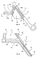
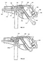
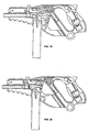
- Figures 4-6 show a cut-away view of the internal parts and the operation of the system in an exemplary embodiment.
- a cartridge is loaded and chambered in the barrel, with bolt (501) holding the cartridge securely.
- the bolt is designed to allow the hammer assembly (502) and more particularly the striking surface of the hammer (503) to rotate through a slot to cause the cartridge to fire.
- the hammer is in a cocked position so that a notch (504) on the axial portion of the hammer is engaged by the cocking lever (506).
- the hammer spring (505) provides forces to rotate the hammer.
- Trigger (507) which is held in tension through trigger spring (508), can be pulled to initiate operation of trigger mechanism and firing of cartridge.
- Pulling trigger (507) forces rocking lever (509) to move, which rotates hammer so that striking surface of hammer (503) is moved further away from cartridge.
- the cocking lever then rotates and disengages from notch on axial surface of hammer (504).
- the hammer rotates on axis around its pin (515) allowing striking surface (503) to move through slot on top of bolt to fire chambered round.
- Figure 5 shows the configuration just after firing.
- Initial sloped surface (511) of slider (510) can be seen as bolt moves into contact with second sloped surface (512) of slider.
- Bolt contacts hammer and causes hammer to rotate around pin (515), now rotating in the opposite direction compared to the firing configuration just described.
- end section of bolt in contact with slider moves toward backward-most end of slider, slider moves downward along a guide or path.
- the guide or path can be integrally formed as part of frame of the firearm, or optionally, guide or path can be an internal part of firearm.
- the hammer contacts separator (513) and separator rotates to engaged position on a second notch (514) on axial surface of hammer.
- cocking lever (506) remains up so that it does not engage notch (504).
- the bolt tilts as it moves back ( Figure 6 ) so that ejector (516) and extractor (522) displace cartridge case from bolt and the projections on bolt (519).
- Slider moves downward to redirect recoil forces and counteract upward jerk of barrel.
- Figure 6 shows bolt and slider at end of movement (518).
- Bolt and slider can be formed with one or more projections or tenons that are designed to move along or in paths defining a range of motion.
- a recoil spring or return device not shown, forces slider up guide or path. Slider, in connection with bolt, pushes bolt upward and forward to engage next round from magazine.
- a second cocking lever with cocking lever spring, can engage a separate or existing notch on axial surface of hammer to catch hammer before it rotates down to fire cartridge.
- the second cocking lever for semi-automatic will prevent automatic firing and allow only one round to fire per trigger pull.
- One of skill in the art can adapt the cocking lever or add an additional cocking lever so that it engages a notch on the axial surface of the hammer after each time the hammer moves backward after firing.
- the cocking lever used for the semi-automatic action can be connected to a switch on the frame or a switch extending through the frame so that the operator can select between semi-automatic or automatic action.
- the switch effectively places the appropriate cocking lever in connective position with the notch on the hammer, or allows repeated firing through the movement of the separator.
- a burst firing mechanism can also be adapted, as known in the art, so that a certain number of rounds are fired automatically.
- the handgrip and trigger can be designed to separate from the frame in order to prevent firing of the firearm.
- the handgrip and trigger components can further be equipped with personal security devices so that only designated users can assemble or operate the firearm.
- Figure 3 shows a cutaway view of the same embodiment of Figures 4-6 , except that an optional manual cocking lever (520) extends through the bottom of the frame.
- the separator (513) is engaged in the second notch on axial surface of hammer (512), and the slider (510) is in position to contact separator from below to disengage it from notch (514) and release hammer (502) so that striking surface of hammer can fire cartridge.
- the slider is linked to bolt (501) through pin (not shown) extending through slot (517) in slider.
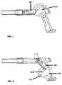
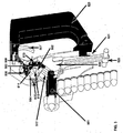
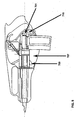
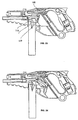
- FIGs 1-2 show schematically a double-angled slider (510) and its movement in a receiver of guide.
- Bolt (501) is linked to slider and initial surface of slider (511) and second sloped surface of slider (512) are visible.
- the spent cartridge case is being ejected from bolt head.
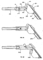
- Figures 1-5 can be used for a handgun, the same mechanisms can be adapted for a rifle. Additional options can be incorporated to either the handgun or rifle. In one example, which can be suitable for .308 caliber ammunition, a gas injection system can be incorporated. Further, as shown in Figures 7-8 , the slider can be positioned in other areas of the firearm. Figures 7-8 show a slider positioned above the barrel and in front of the bolt. In Figure 7 , bolt (701) is in loaded position at chambering end of barrel (702). A trigger mechanism (703) causes hammer (704) to fire cartridge.
- the gas injection system (705) forces pressurized air through tube (706), which initiates movement of bolt (701) back and slider (707) down path defined by return device (708).
- return device Typically, a spring is used as the return device. Movement of the slider down its path redirects recoil forces and virtually eliminates upward jerking of the barrel upon firing.
- Slot (709) in slider connects with initial gas impulse transferring mechanism (not shown). Either a single-angled or double-angled slider can be selected, or indeed, a multiple-angled slider or slider with multiple shapes on its surface. Here, a single-angled slider is shown in Figure 8 and the lower end of slot (709). In Figure 8 , the slider (707) has moved to its downward-most position.
- Feeding lock (710) releases next round from magazine (711), which can be chambered by bolt (701).
- the firing action can be single-shot, semi-automatic, burst firing, or fully automatic.
- an electronic or other non-mechanical firing mechanism can be used.
- the placement of the handgrip (713) relative to the middle of the axis of the gun barrel (712) can take advantage of reduced interior clutter the new recoil devices allow.
- the handgrip is positioned below the middle of the axis of the barrel. This exacerbates recoil effects and adds to the reactive upward jerking upon firing.
- the handgrip can be positioned at a point where the middle of the axis of the barrel intersects a line at approximately 70% of the height of the handgrip relative to the top of the handgrip.
- the middle of the axis of the barrel intersects the handgrip at approximately 50% of the height of the handgrip.
- the range of possible positions for the handgrip relative to the middle of the axis of the barrel can vary by design factors or by the desired recoil control characteristics.
- the handgrip is positioned so that the axis of the gun barrel is in line with the middle of the wrist, or positioned at a line formed by the middle of the arm through the middle of the wrist of the operator holding the handgrip.
- the middle of the axis of the barrel can intersect the handgrip at a range of positions, for example from about 10 to about 30% of the height relative to the top, from about 30 to about 50% of the height, from about 50 to about 70% of the height, from about 70 to about 90% of the height, or about 5 to about 95% of the height.
- the middle of the axis of the barrel can even be below or above the handgrip.
- other parts of the frame can be modified to allow both hands to grip the firearm.
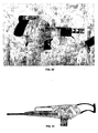
- Figure 32 shows a number of examples.
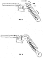
- Figure 1 is a schematic of the mobile breech and the reciprocating operation of a preferred double-angled slider embodiment of the recoil control device according to the invention.
- the slider is at the lowest end of its cycle and the bolt head is at the back-most end of its cycle.
- Figure 1 shows the same slider embodiment at its closed position, where the slider is at it upper end of its cycle and the bolt head is furthest forward.
- the mobile breech comprises bolt head and inertia block.
- the inertia block can be referred to as a sliding mechanism or a "slider" and these terms are used interchangeably.
- the slider can take various forms, for example a trapezoid, but many other forms and shapes are possible.
- the slider is articulated with the bolt head close to its rear extremity, optionally by a transverse spindle, which can take the form of a machined tenon or pin on the bolt head projecting on either side.
- the bolt head can have a second tenon or pin, also projecting on both sides, in its foremost section that engages a guidance ramp to guide the cyclic path of bolt head.
- the performance of a semi-automatic or automatic firearm can be improved by using a double-angled slider, characterized by an oblique slot (517 in Figure 3 ), comprising two sloped surfaces (511 and 512 of Figure 6 or Figure 2 ).
- the length of each sloped surface can vary.
- the forward-most sloped surface engages the bolt head or bolt head articulation mechanism when the round is chambered and/or when the bolt head is locked, so that the bolt head is prevented from moving backward (the configuration of Figure 1 and 4 , for example).
- a trigger mechanism in operating linkage to the hammer which strikes the cartridge on the bolt or contacting the bolt. Conventional mechanisms can be adapted for use with the invention or in designing a firearm.
- the action of the mobile breech and bolt head can be controlled within its movement to appropriately chamber and eject successive rounds.
- the bolt head tilts relative to the barrel.
- the spent round is ejected using a conventional ejector and extractor devices.
- the forward moving bolt head catches the end of the cartridge and inserts the round into the chamber.
- FIGs 7-8 a configuration designed preferably for a .308 caliber or 7.62 NATO round is shown.
- the slider (707) here is positioned above and forward of the bolt head (701), and the cycle action takes the slider through a downward and upward trajectory.
- the slider and bolt head articulating mechanisms are located above the bolt head to conserve space for a magazine below the barrel.
- optional designs configurations can also include slider and bolt head articulating mechanisms below the bolt head, to allow for magazines on the top of the barrel or above or to the side of the barrel.
- a safety clip or feeding lock (710) is optionally included to prevent loading or firing of rounds at other than the desired time.
- the safety clip (710) moves in response to the cartridge and clips the top edge of each cartridge.
- Figures also show a triggering mechanism.
- the layout and design of the triggering mechanism can be selected from many available options and one of ordinary skill can devise an appropriate or preferred triggering mechanism.
- Figure 7 shows the round chambered and locked, with the slider (707) at its utmost position. After firing, the slider moves to its fully displaced position ( Figure 8 ), partially or largely below the barrel.
- the slot (709) for connecting the slider to the bolt head can be seen in both Figures.
- Figure 8 the optional double-angled surface of the slider is visible.
- the performance of a semi-automatic or automatic firearm can be improved by using a double-angled slider.
- the rear edge of slider (510) has a pair of lateral flanges extending from either side of the slider and positioned to slide in the guidance grooves of the guide or receiver.
- the guidance grooves have a slope relative to the axis of the barrel, which presents an angle ( ⁇ ), shown in Figure 20 , and preferably set between 30 and 36.
- the slope of the parts shown presents an angle ( ⁇ ), the variance of which changes the firing rate of the firearm.
- the angle ( ⁇ ) preferably is between 24 and 36 degrees.
- an angle ( ⁇ ) of about 36 to about 37 degrees allows a firing rate of approximately 900 rounds per minute.
- An angle ( ⁇ ) of approximately 32.5 degrees can correspond to a firing rate of approximately 2000 rounds per minute.
- angle ( ⁇ ) There is a practical minimum value for angle ( ⁇ ) below which mechanical blockage occurs and little or no articulation is possible. This minimum angle is a function of the power of the ammunition used, and is approximately 6 degrees for the standard .45 ACP ammunition of the Examples below.
- the use of two slopes in the slot or surface of the slider allows the designer to vary the rate of fire, to reduce or alter the mass of the slider, or reduce or alter the mass of the bolt for a given caliber ammunition.
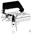
- Figure 9 shows the mobile breech, which consists of bolt head (103), pin rod (104) and inertia block (102).
- the pin rod (104) preferably is joined to the bolt head (103) close to its rear extremity by means of a transverse spindle (108) projecting on both sides of bolt head (103).
- the front of the bolt head preferably has a transverse stud or linking-pin (113) also projecting on both sides of bolt head (103).
- the pin rod (104) preferably is articulated in proximity to its second end by a transverse stud or spindle (109) with the forward part of the inertia block (102).
- the transverse stud (109) engages a longitudinal groove (114) in the pin rod (104).
- Figure 9 shows the mobile breech in extension, with transverse stud (109) in the back of groove (114).
- the bolt head (103) and the inertia block (102) may or may not be in contact.
- Inertia block (102) and bolt head (103) present complementary sloping contact surfaces (P102 and P103, respectively), which preferably are separated somewhat by some minor play engendered by groove (114).
- stud (109) slides in groove (114) the surfaces of the bolt head and the inertia block make contact at their sloped ridges, (P102 and P103), which are parallel.
- the inertia block (102) is generally cylindrical and oblong in form. In the back is a recess (115) in which is fitted a reset spring (111). The tip of the spring bears a part (117), which slides at compression and links with the bolt housing.
- the inertia block has longitudinal flanges (116) on either side designed to fit the housing's guidance slots.
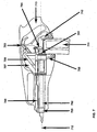
- This mechanism fits within the breech housing (101) shown in cutaway in Figure 10 (embodiment not forming part of the invention), the general "V” form of which creates a cavity also in “V” shape, with two arms, C and C 1
- the breech housing at its forward extremity supports the gun barrel (154) and receptacles for a magazine underneath (118). It has an ejection slot (119) situated in the top of this embodiment. Alternately, the slot could be located laterally without prejudice to the performance of the mechanism.
- each side of the casing preferably has a guidance ramp (106) in "V" shape in the form of a groove accommodating the respective projections of the spindles (108 and 109) articulating the bolt head (103), with the pin rod (104) and with the inertia block (102), as well as the extremities of stud (113) and flange (116).
- the head of the V of the ramp is rounded.
- Figures 11 to 18 show the movement of a pistol, not covered by the claims and not forming part of the invention, equipped with a moment control mechanism similar to that shown in Figures 9 and 10 .
- the trigger, percussion and ejection mechanisms are not shown to simplify the drawing. To the extent not described herein, triggering, percussion, and ejection may be accomplished by conventional methods well known to those skilled in the art.
- Figure 11 shows the embodiment of Figure 9 with bolt closed.
- a round is chambered.
- the bolt head (103) is in its position preceding percussion.
- the trigger has been pressed and the cartridge is on the point of being struck.
- the mobile breech is extended with the transverse spindle (109) linking inertia block (102) and pin rod (104) in the back of the oblong slot that houses it.
- the bolt head (103) and the inertia block (102) are separated only by a very slight play.
- the slopes P102 and P103 initially slide against each other, imparting an impulse from pin rod (104) to inertia block (102), then separate.
- the mobile breech's movement forward continues as illustrated in Figure 17 .
- the spindle (108) goes over the rounded top of the guidance ramp, the orientation of the pin rod (104) changes, so that it is freed from the edge (122) of the inertia block.
- the spindle (109) slides forward in the slot (114) and the mobile breech recovers its compact configuration while bringing another round in line with the barrel.
- the cartridge In passing from the stage shown in Figure 17 to the phase shown in Figure 18 , the cartridge is chambered under pressure by the bolt head (103). It is in direct contact with the inertia block via sloped surfaces (P102 and P103), which slide over each other as the spindle (109) slides in the slot (114). The parts of the mobile breech have regained the configuration of Figure 11 .
- the moving parts act within a closed casing.
- the user is not in contact with critical moving parts, cocking lever or other components of the mechanism.
- This approach allows use of space normally neglected in pistols or in machine pistols having the magazine placed in front of the bridge, namely, the butt.
- the mechanism here described also enables reduction of the length of the bolt housing.
- the embodiment of Figure 19 shows the mobile breech, which comprises bolt head (103) and inertia block (102).
- the inertia block (102) is articulated with the bolt head (103) close to its rear extremity, preferably by a transverse spindle (109), which can take the form of a machined tenon on the bolt head projecting on either side.
- the bolt head has a second tenon (110), also projecting on both sides, in its foremost section that engages guide ramp (106) to guide the cyclic path of bolt head (103).
- the spindle (109) can slide within the oblique slot (208) housed in the anterior section of the inertia block (102).
- Figure 19 displays the mobile breech in a position corresponding to the one at percussion: the spindle (109) is in the forward-down extremity of the slot (208).
- the slot (208) of the inertia block (102) has, one turned toward the other, two parallel lateral slopes (111 and 112) of the same pitch (P1), separated in order that the spindle (109) lodges with slight play in the direction of the gun barrel's axis.
- the bolt head (103) alternately makes contact with either the backward lateral slope (111) or the forward lateral slope (112) of the slot (208).
- the inertia block (102) preferably has the form of a trapezoid.
- the inertia block can be referred to as a sliding mechanism or a slider and these terms are used interchangeably herein.
- the full length of the rear edge of inertia block (102) has a pair of lateral flanges (107) extending laterally from either side of the inertia block (102) and positioned to slide in the guidance grooves (105) of the breech block, as shown in Figure 19 .
- Guidance grooves (105) have a slope (P2), which presents an angle ( ⁇ ), shown in Figure 20 and preferably set between 30 and 36 degrees in relation to the axis of the barrel.
- the flange (107) also has a slope (P2) in relation to the axis of the barrel, which itself is horizontal.
- the recoil energy recuperation mechanism is shown in Figure 19 to the right of the inertia block (102).
- the recuperation mechanism includes a cocking lever (115) with a ring (114) to enable manipulation.
- the cocking lever (115) is hollow and forms a sleeve for the return spring (116).
- the spring (116) is turned around a rod (117).
- the cocking lever (115) slides over it in compressing or extending the return spring (116).
- the rod (117) is linked with the upper end of the breech block via ring (118) at fitting (150).
- a lug (119) on the cocking lever (115) manipulates the inertia block (102) conventionally.
- a stud (151) is provided to anchor the trigger mechanism.
- This mobile breech and recuperation mechanism operate within the breech block (101) as shown in cutaway in Figure 20 , its form preferably roughly that of the letter Y, having three arms, C1, C2, C3, and creating a guidance ramp (106) in roughly the form of the letter V.
- the embodiment of Figure 20 shows, on each side of the breech casing, a guidance ramp in the form of a "V" in a groove (106), which accommodates, respectively, the extremities of the spindle (109) which articulate the bolt head (103) with the inertia block (102), as well as the extremities of a tenon (110), which guides the forward end of bolt head (103).
- the head of the V of the guidance ramp (106) is rounded.
- the front arm C1 of the breech casing bears the forward section (106a) of the groove (106), which is arranged in the extension of the axis of the gun barrel, and the rear arm, C3, of the breech casing bears the rear section (106c) of the groove (106).
- Rear section (106c) features a slope (P2) in relation to the barrel's axis, which presents an angle ( ⁇ ) between the axis of the rear section (106c) and the axis of the barrel, preferably between 30 and 36 degrees.
- Each side of the breech block also features a groove (105), which is substantially parallel to the section at (106c) of the groove (106), and set to accommodate a flange (107) of the inertia block (102), which extends from section (C3) into the upper Y (C2) of the breech block.
- Figures 21 to 26 illustrate the functioning of a semiautomatic or automatic handgun equipped with the recoil control device shown in Figures 19 and 20 . Sighting, percussion and ejection functions, are not shown in order to ease understanding of the recoil control device.
- the bolt head (103) preferably contains the percussion device.
- Figures 21 and 26 show the top of the hammer lug (141) projecting over the head of the bolt head (103). The technique governing the action of the hammer and its integration with the internal release are conventional.
- Figures 21 to 26 also show an optional infrared sighting device (123) mounted on the barrel and a battery (124) housed in the handgrip (125) to service it.
- the gun barrel (154) and the infrared sight (123) are contained within a sleeve for protection.
- the breech block (101) supports the barrel (154).
- An ejection slot preferably is laterally placed and fitted with receptacles for a magazine below.
- the breech block housing and the mobile breech are integrated into an exterior housing offering a minimum of exposed moving parts.
- the recoil energy recuperator is housed at the back of arms C2 and C3 of the breech block housing.
- a grip is located behind the recuperator that preferably is linked with the housing enclosing the breech block, both by lower arm (142), and upper arm (128).
- the grip (125) contains a safety lever (129) and the automatic or semi-automatic switch (130).
- the firing device (131) is preferably located in the part of the housing (128) that links the upper portion of the grip with the breech lock.
- the principal internal trigger (135) and the automatic internal firing release (132) are located in front of firing device (131) and are articulated at the upper extremity of the C1 arm of the breech block at stud (121).
- the functioning of these parts is conventional. Their placement in the overhead portion of the housing is specific to the embodiment of Figures 19-26 .
- Figure 22 shows the embodiment of Figure 21 with the breech in closed position.
- a round is chambered.
- the bolt head (103) is in the pre-percussion position.
- Hammer lug (141) of the hammer is socketed in an indentation of the principal tumbler (133).
- the trigger can be actuated and the cartridge struck when the gun has been taken up and the safety catch is released.
- the inertia block (102) of the mobile breech is in a forward-up position, with at least an upper portion of the inertia block in position above the axis of the gun barrel.
- the transverse spindle (109) linking inertia block (102) and bolt head (103) is positioned in the forward-down (208a) portion of the oblong slot (208) of the inertia block (102), which houses it.
- the rear extremities of the bolt head (103) and the inertia block (102) are separated only by a slight margin of play.
- the spindle (109) goes over the rounded top (106b) of the V of the ramp.
- the trajectory of the bolt head (103) curves toward the bottom of the gun.
- Figures 21 to 26 show that the assembly of moving parts is confined in closed housing. The user thus is not in contact with projecting, moving parts.
- Figures 27, 28 and 29 illustrate a preferred embodiment of the moment control mechanism in which the movement of the slider is no longer one of pure translation but of translation to which is added an oscillation at the instant of recoil.
- the slider's movement exploits the same guide groove as the bolt head and a pressure roller located behind the slider.
- the gun has a breech block, (201), in inverted V form, which has a guide rail (206), also in V form in the mass of the side of the breech head.
- the bolt head (203) slides in the rail (206) by means of tenons (209) and (210), as in the embodiment of Figures 19-26 .
- the bolt head (203) is articulated with slider (202) by tenon (209), which engages oblong slot (208) in the forward edge of the slider (203).
- the forward-down extremity of slot (208) has a skewed extension (208a) with a recess as shown in Figure 32 .
- a recess (211) is situated in the rear of the slider, which slides on a pressure roller (205).
- the recess (211) and the skewed extension (208a) of the slot are arranged to cooperate at the start and the finish of the firing cycle.
- the slider has a tenon (207), which slides in the lower portion (206c) of the guidance ramp (206).
- the guidance ramp (206) also accommodates tenons (209 and 210) of the bolt head in its horizontal portion (206a).
- this preferred embodiment for the recoil control device is by and large the same as that portrayed in Figures 19-26 .
- This embodiment differs from the embodiment of Figures 19-26 in that at percussion the bolt head (203) presses the slider (202) between tenon (209) at the rear extremity of bolt head (203), and the pressure roller (205). The slider (202) is then expelled downward towards the bottom of the gun at a rate of displacement that is a function of the decoupling angles presented by the slopes of skewed extension (208a) and recess (211) on either side of the slider.
- the slider (202) Once the full rate of displacement of the slider (202) is achieved, it becomes the motor of the system and carries the bolt head to the rear with tenon (209) traveling in slot (208), the bolt head sliding in the segment (206a) of groove (206). At the start of its displacement towards the rear, the slider (202) tilts on its lug (207) in its lower section. On the other hand, an inverse oscillation by the slider at the end of its return has a dampening effect as the bolt head regains a closed configuration, its cartridge chambered.
- a series of exemplary .45 caliber machine pistols or handguns is produced, wherein the slider has a weight of between about 150 grams to about 175 grams, the bolt head has a weight of between about 50 grams to about 70 grams.
- the return device or recoil spring used has a 8.5 kg tare to about 11 kg tare.
- One example employs a double-angle slider, similar to the embodiments of Figures 3-6 and incorporating the elements of the invention, and is presented with the following characteristics: length of barrel: approx 3-4 inches; initial angle of sloped surface of slider relative to barrel axis: 36 degrees or 44.5 degrees; weight of bolt head 52g; weight of inertia block 152 g; tare, recoil spring 8.4 kg.
- the operational characteristics give a theoretical firing rate: 950-1000 rounds/min.
- Firing tests gave subjective impression of very smooth working part movement, with a noticeable reduction or quasi-total absence of the phenomenon of recoil. Additional testing with single rounds and eight round bursts (automatic action) also showed remarkable reduction of recoil with .45 caliber rounds and an elimination of upward jerking forces compared to a conventional .45 caliber handgun.
- a .45 caliber automatic machine gun is produced using a double-angled slider having a downward slider path similar to those shown in Figures 3-6 .
- the weight of the bolt head is 56 g and the weight of the inertia block is 172 g.
- the firearm was discharged in 5 round bursts and compared to the M3-3A1 automatic submachine gun ("grease gun") and a handheld Colt M1911 .45 caliber pistol.
- the upward jerking forces produce a noticeable and pronounced upward movement of the end of the barrel for the grease gun and pistol.
- the firearm employing the device of the invention shows relatively little or no upward movement when handled and fired in similar circumstances.
Landscapes
- Engineering & Computer Science (AREA)
- General Engineering & Computer Science (AREA)
- Toys (AREA)
- Aiming, Guidance, Guns With A Light Source, Armor, Camouflage, And Targets (AREA)
- Percussive Tools And Related Accessories (AREA)
Claims (23)
- Rückstoßkontrollvorrichtung zur Verwendung in einer Feuerwaffe, wobei die Vorrichtung umfasst:- einen Bolzenkopf (501), der so ausgestaltet ist, dass er in Reaktion auf das Abfeuern einer oder mehrerer Patronen zwischen einer vorderen Stellung und einer hinteren Stellung abwechselt; und- einen Schieber (510), der mit dem Bolzenkopf (501) verbunden ist;- wobei der Schieber (510) einen schrägen Schlitz (517) umfasst, der umfasst:- eine anfängliche erste geneigte Fläche (511) und- eine zweite geneigte Fläche (512),wobei der schräge Schlitz (517) so ausgelegt ist, dass er eine Querspindel oder einen Querstift aufnimmt, der den Bolzenkopf so mit dem Schieber verbindet, dass die anfängliche erste geneigte und die zweite geneigte Fläche des Schiebers den Bolzenkopf oder eine Verbindung zum Bolzenkopf berühren,
derart dass der Schieber mit dem Bolzenkopf gelenkig angebracht wird,- wobei der Bolzenkopf (501) so ausgestaltet ist, dass er bei der Rückwärtsbewegung des Bolzenkopfs (501) aus der vorderen Stellung in die hintere Stellung einen Impuls an den Schieber (510) sendet,- wobei die Bewegung des Schiebers (510) eine Komponente senkrecht auf die Schussachse des Laufs der Feuerwaffe aufweist,- um die Rückstoßkräfte impulsiv in einer Richtung seitlich zur Längsachse des Laufs zu übertragen, wenn der Bolzenkopf (501) während seiner Rückwärtsbewegung aus der vorderen in die hintere Stellung aus der Längsachse des Laufs kippt. - Rückstoßkontrollvorrichtung nach Anspruch 1, ferner umfassend eine Bolzenkopfführung, die so angeordnet ist, dass wenigstens die anfängliche Rückwärtsbewegung des Bolzenkopfs (501) aus der vorderen Stellung im Wesentlichen entlang der Schussachse des Laufs erfolgt, und eine Schieberführung, die so angeordnet ist, dass sie den Schieber (510) in einer Bewegung quer zur Schussachse des Laufs führt.
- Rückstoßkontrollvorrichtung nach Anspruch 2, wobei die Schieberführung es dem Schieber (510) ermöglicht, sich zwischen einer Stellung vorne oben, die der vorderen Stellung des Bolzenkopfs (501) entspricht, und einer Stellung hinten unten zu bewegen, die der hinteren Stellung des Bolzenkopfs (501) entspricht.
- Rückstoßkontrollvorrichtung nach einem der Ansprüche 2 bis 3, wobei die Schieberführung einen Winkel von etwa 5 Grad bis etwa 45 Grad mit der Schussachse des Laufs darstellt.
- Rückstoßkontrollvorrichtung nach Anspruch 3 oder 4, wobei die Schieberführung einen ersten geneigten Abschnitt und einen zweiten geneigten Abschnitt umfasst.
- Rückstoßkontrollvorrichtung nach Anspruch 5, wobei der Winkel zwischen dem zweiten geneigten Abschnitt der Schieberführung und der Schussachse des Laufs etwa 30 Grad bis etwa 43 Grad, insbesondere etwa 30 Grad bis etwa 36 Grad beträgt.
- Rückstoßkontrollvorrichtung nach Anspruch 5 oder 6, wobei die Verbindung, die den Bolzenkopf (501) und den Schieber (510) verbindet, eine Querspindel senkrecht auf die Achse des Laufs umfasst, wobei die Spindel mit dem Bolzenkopf (501) verbunden und so angeordnet ist, dass sie sich zwischen dem ersten geneigten Abschnitt, wenn der Bolzenkopf (501) in der vorderen Stellung ist, und dem zweiten geneigten Abschnitt verschiebt, wenn der Bolzenkopf (501) in der hinteren Stellung ist.
- Rückstoßkontrollvorrichtung nach Anspruch 7, wobei die Querspindel, die den Bolzenkopf (501) und den Schieber (510) verbindet, so eingestellt ist, dass sie einen Spielraum in der Längsrichtung aufweist.
- Rückstoßkontrollvorrichtung nach Anspruch 8, wobei der Bolzenkopf (501) mit der Spindel versehen ist.
- Rückstoßkontrollvorrichtung nach einem der Ansprüche 1 bis 9, wobei der Bolzenkopf (501) eine vordere geneigte Fläche umfasst, um mit wenigstens einer der ersten und zweiten geneigten Flächen (511, 512) auf dem Schieber (510) Kontakt zum Senden des Impulses herzustellen.
- Rückstoßkontrollvorrichtung nach einem der Ansprüche 1 bis 10, wobei der erste Winkel, der durch die anfängliche erste geneigte Fläche (511) des Schiebers (510) und die Schieberführung oder den zweiten Abschnitt der Schieberführung gebildet wird, etwa 6 Grad bis etwa 40 Grad beträgt, und wobei der zweite Winkel, der durch die zweite geneigte Fläche (512) und die Schieberführung oder den zweiten Abschnitt der Schieberführung gebildet wird, etwa 24 Grad bis etwa 36 Grad beträgt.
- Rückstoßkontrollvorrichtung nach einem der vorhergehenden Ansprüche, wobei das Verhältnis von Schiebermasse zu Bolzenkopfmasse ungefähr 2 bis ungefähr 4, insbesondere 2,5 bis ungefähr 3 beträgt.
- Feuerwaffe, umfassend eine Rückstoßkontrolle mit einem Verschlussgehäuse, umfassend eine Rückstoßkontrollvorrichtung nach einem der vorhergehenden Ansprüche.
- Feuerwaffe nach Anspruch 13, wobei das Verschlussgehäuse einen Hohlraum aufweist, wobei der Hohlraum ein vorderes äußerstes Ende, von dem sich der Lauf der Schusswaffe erstreckt, ein Behältnis für ein Magazin, ein vorderes Teilstück, das den Bolzenkopf beherbergt, und ein hinteres Teilstück umfasst, das den Schieber und einen Rückfederungsmechanismus beherbergt.
- Feuerwaffe nach Anspruch 14, wobei die Seiten des Verschlussgehäuses jeweils eine Führungsschiene zum Unterbringen der jeweiligen äußersten Enden der Querspindel bildet.
- Feuerwaffe nach einem der Ansprüche 13 bis 15, umfassend:einen Lauf mit einem Kammerungsende und einem Mündungsende; undeinen Handgriff mit einem oberen Ende und einem unteren Ende, wobei der Handgriff hinter dem Kammerungsende des Laufs positioniert ist, und wobei der Handgriff in Bezug auf den Lauf derart positioniert ist, dass die Längsachse des Laufs den Handgriff bei etwa 10 % bis etwa 95 % der Höhe in Bezug auf das obere Ende des Handgriffs schneidet.
- Feuerwaffe nach Anspruch 13 bis 16, ferner umfassend einen Separator, der funktionell mit einem Hammer verbunden ist und sich in Reaktion auf den Bolzenkopf und den Schieber so bewegt, dass sukzessive Patronen aus einem Magazin in eine Kammer bewegt werden können, die am Kammerungsende des Laufs angebracht ist.
- Feuerwaffe nach Anspruch 17, ferner umfassend eine Zuführsperre, um zu gewährleisten, dass sich jeweils nur eine einzige Patrone aus dem Magazin in die Kammer bewegt.
- Feuerwaffe nach Anspruch 13 bis 18, ferner umfassend eine Mündungsbremse.
- Feuerwaffe nach einem der Ansprüche 13 bis 19, ferner umfassend einen Schaft, der sich hinter dem Lauf der Feuerwaffe befindet.
- Feuerwaffe nach einem der Ansprüche 13 bis 20, wobei die Feuerwaffe für Munition Kaliber .45 ausgelegt ist, und wobei die Bolzenkopfmasse ungefähr 50 bis 70 Gramm beträgt.
- Feuerwaffe nach einem der Ansprüche 13 bis 20, wobei die Feuerwaffe für Munition NATO-Kaliber 7,62 ausgelegt ist.
- Feuerwaffe nach einem der Ansprüche 13 bis 22, wobei die Feuerwaffe automatisch oder halbautomatisch ist.
Applications Claiming Priority (7)
| Application Number | Priority Date | Filing Date | Title |
|---|---|---|---|
| CH9752002 | 2002-06-07 | ||
| CH975022002 | 2002-06-07 | ||
| CH13432002 | 2002-07-31 | ||
| CH134302 | 2002-07-31 | ||
| CH6792003 | 2003-04-15 | ||
| CH679032003 | 2003-04-15 | ||
| PCT/CH2003/000363 WO2003104738A1 (en) | 2002-06-07 | 2003-06-06 | Recoil control device |
Publications (2)
| Publication Number | Publication Date |
|---|---|
| EP1514068A1 EP1514068A1 (de) | 2005-03-16 |
| EP1514068B1 true EP1514068B1 (de) | 2016-08-24 |
Family
ID=29740339
Family Applications (3)
| Application Number | Title | Priority Date | Filing Date |
|---|---|---|---|
| EP03729755.3A Expired - Lifetime EP1514069B1 (de) | 2002-06-07 | 2003-06-06 | Rückstossbeherrschungsvorrichting |
| EP03729753.8A Expired - Lifetime EP1514067B1 (de) | 2002-06-07 | 2003-06-06 | Rückstossbeherrschungsvorrichtung |
| EP03729754.6A Expired - Lifetime EP1514068B1 (de) | 2002-06-07 | 2003-06-06 | Rückstossbeherrschungsvorrichtung |
Family Applications Before (2)
| Application Number | Title | Priority Date | Filing Date |
|---|---|---|---|
| EP03729755.3A Expired - Lifetime EP1514069B1 (de) | 2002-06-07 | 2003-06-06 | Rückstossbeherrschungsvorrichting |
| EP03729753.8A Expired - Lifetime EP1514067B1 (de) | 2002-06-07 | 2003-06-06 | Rückstossbeherrschungsvorrichtung |
Country Status (8)
| Country | Link |
|---|---|
| US (1) | US8813405B2 (de) |
| EP (3) | EP1514069B1 (de) |
| KR (2) | KR101213876B1 (de) |
| CN (3) | CN102506610B (de) |
| AU (3) | AU2003240339A1 (de) |
| CA (3) | CA2724276C (de) |
| NO (1) | NO20050061L (de) |
| WO (3) | WO2003104737A1 (de) |
Families Citing this family (17)
| Publication number | Priority date | Publication date | Assignee | Title |
|---|---|---|---|---|
| US7698987B2 (en) | 2002-06-07 | 2010-04-20 | Gamma Kdg Systems Sa | Heavy caliber firearm with enhanced recoil and control characteristics |
| EP1514069B1 (de) | 2002-06-07 | 2016-12-28 | KRISS Systems SA | Rückstossbeherrschungsvorrichting |
| US7201094B2 (en) | 2002-06-07 | 2007-04-10 | Gamma Kdg Systems Sa | Firearm with enhanced recoil and control characteristics |
| US9038524B2 (en) | 2002-06-07 | 2015-05-26 | Kriss Systems Sa | Firearm with enhanced recoil and control characters |
| CN101306411B (zh) * | 2007-05-18 | 2012-02-22 | 程大祥 | 化解反冲力式电动喷枪 |
| US10281233B2 (en) | 2011-09-30 | 2019-05-07 | Ra Brands, L.L.C. | Recoil reducer |
| WO2014123628A2 (en) * | 2012-12-18 | 2014-08-14 | Revol Arms Llc | Semiautomatic pistol |
| CN104236383B (zh) * | 2013-06-11 | 2017-06-27 | 张军帅 | 枪炮后坐力消除器 |
| DE102015008799B4 (de) * | 2015-07-10 | 2021-05-27 | Rheinmetall Waffe Munition Gmbh | Rückstoßverstärker einer fremdangetriebenen Maschinenwaffe, insbesondere eines Maschinengewehrs |
| US10545005B2 (en) * | 2017-03-16 | 2020-01-28 | In Ovation Llc | Firearm delay mechanism |
| US10775121B2 (en) | 2017-06-29 | 2020-09-15 | In Ovation Llc | Firearm mechanism |
| RU2708131C1 (ru) * | 2018-11-09 | 2019-12-04 | Виктор Леонидович Шевченко | Механизм запирания автоматического оружия |
| RU200594U1 (ru) * | 2019-06-18 | 2020-10-30 | Федеральное государственное казенное военное образовательное учреждение высшего образования "Военная академия материально-технического обеспечения имени генерала армии А.В. Хрулёва" | Автомат с боевыми упорами |
| US12253324B2 (en) | 2022-03-07 | 2025-03-18 | In Ovation Llc | Firearm action mechanism |
| US12235063B2 (en) * | 2023-01-09 | 2025-02-25 | Joshua MAY | Firearm with multi-part chamber locking assembly |
| TR2023005453A2 (tr) | 2023-05-16 | 2023-05-22 | Ata Silah Sanayi Anonim Sirketi | Ateşli Silahlar İçin Hızlı Sökülebilir İcra Grubu Yapılanması |
| US12104866B1 (en) | 2023-05-24 | 2024-10-01 | Ata Silah Sanayi Anonim Sirketi | Quick disassembly recoil group structure for firearms |
Citations (1)
| Publication number | Priority date | Publication date | Assignee | Title |
|---|---|---|---|---|
| US1464864A (en) * | 1921-09-27 | 1923-08-14 | John M Browning | Firearm |
Family Cites Families (106)
| Publication number | Priority date | Publication date | Assignee | Title |
|---|---|---|---|---|
| BE351672A (de) * | ||||
| US214098A (en) * | 1879-04-08 | Improvement in breech-loading fire-arms | ||
| FR1193803A (de) * | 1959-11-05 | |||
| US574189A (en) | 1896-12-29 | Recoil operated firearm | ||
| FR384597A (fr) * | 1908-01-18 | 1908-04-14 | Uldarique Marga | Arme à feu |
| US1452123A (en) | 1919-07-14 | 1923-04-17 | mccrudden | |
| US1457961A (en) * | 1921-04-13 | 1923-06-05 | John M Browning | Firearm |
| US1497096A (en) * | 1924-06-05 | 1924-06-10 | Eriksen Johan | Machine gun |
| US1835715A (en) * | 1929-03-14 | 1931-12-08 | Mccoy Earl | Firearm |
| US2365188A (en) * | 1943-03-10 | 1944-12-19 | Walter T Gorton | Firearm |
| FR917290A (fr) * | 1945-07-09 | 1946-12-31 | Expl Des Brevets M G D Soc Pou | Perfectionnements aux fusils automatiques |
| US2476232A (en) * | 1947-11-06 | 1949-07-12 | Olin Ind Inc | Inertia operated bolt lock |
| FR969669A (fr) * | 1948-07-21 | 1950-12-22 | Anciens Ets Hotchkiss & Cie | Perfectionnements aux armes automatiques légères |
| US3000268A (en) * | 1952-09-12 | 1961-09-19 | Russell S Robinson | Toggle lock for breech bolt |
| DE1180283B (de) | 1963-03-09 | 1964-10-22 | Rheinmetall Gmbh | Stossdaempfer fuer automatische Waffen |
| DE1972428U (de) | 1967-04-22 | 1967-11-09 | Ditta F Lli Marocchi D Stefano | Automatischer kleinkaliber-rueckstosslader mit verzoegerter verschlussoeffnung. |
| US3580132A (en) | 1968-09-25 | 1971-05-25 | Olin Mathieson | Buffer and delay mechanism for a firearm |
| US3568565A (en) | 1968-11-25 | 1971-03-09 | Us Army | Buffer device with energy discharge means |
| US3554077A (en) | 1969-04-21 | 1971-01-12 | Harold A Schlapia Jr | Delay blowback mechanism for firearms |
| US3683534A (en) | 1969-11-28 | 1972-08-15 | Marvin A Davis | Gun recoil reducer |
| US3641867A (en) | 1970-03-11 | 1972-02-15 | Ralph Daniel Junker | Reduced recoil caseless cartridge machine gun |
| US3650060A (en) | 1970-03-13 | 1972-03-21 | Donald R Schubert | Inertial recoil reducer for magazine firearms |
| US3661049A (en) | 1970-03-18 | 1972-05-09 | Walter E Perrine | Gas operated toggle action weapon |
| BE792340A (fr) | 1971-12-07 | 1973-03-30 | Perrine Walter E | Pistolet automatique (arme a feu) |
| US4052926A (en) | 1974-11-19 | 1977-10-11 | Ithaca Gun Company, Inc. | Charging handle for a gas-operated shotgun |
| US4088057A (en) | 1976-12-03 | 1978-05-09 | Remington Arms Company, Inc. | Recoil reducing and piston shock absorbing mechanism |
| DE2658770C2 (de) | 1976-12-24 | 1983-12-08 | Rheinmetall GmbH, 4000 Düsseldorf | Vorrichtung an einer automatischen Rohrwaffe zum Steuern deren Schußfolge (Kadenz) |
| US4126077A (en) | 1977-01-18 | 1978-11-21 | Quesnel Henry R | Recoil reducing system for rifles, guns, cannons and the like |
| US4112605A (en) | 1977-06-20 | 1978-09-12 | Staub John W | Gun recoil reducer |
| US4172408A (en) | 1977-08-29 | 1979-10-30 | The United States Of America As Represented By The Secretary Of The Navy | Liquid propellant gun, breech pressure axial injection |
| US4167890A (en) * | 1977-09-01 | 1979-09-18 | Adams Gregory A | Direct drive toggle action |
| US4183282A (en) | 1977-09-01 | 1980-01-15 | Perrine Walter E | Toggle actuating, shell loading and ejecting apparatus for hand held guns |
| US4164825A (en) | 1978-04-21 | 1979-08-21 | Hutchison Louis C | Device for reducing firearm recoil |
| US4301712A (en) | 1979-05-07 | 1981-11-24 | Cristina Salvatore J | Device for controlling the degree of blowback delay in automatic weapons |
| DE2936883A1 (de) | 1979-09-12 | 1981-04-02 | J.G. Anschütz GmbH, 7900 Ulm | Wettkampfschusswaffe, insbesondere rueckstossfreie druckluftschusswaffe oder handfeuerwaffe |
| US4279091A (en) | 1979-12-03 | 1981-07-21 | Edwards Jesse B | Firearm recoil reducer |
| US5445604A (en) | 1980-05-22 | 1995-08-29 | Smith & Nephew Associated Companies, Ltd. | Wound dressing with conformable elastomeric wound contact layer |
| US4447975A (en) | 1981-03-18 | 1984-05-15 | Ljutic Albert V | Gun with reduced recoil |
| US4398116A (en) | 1981-04-30 | 1983-08-09 | Siemens Gammasonics, Inc. | Transducer for electronic focal scanning in an ultrasound imaging device |
| US4373519A (en) | 1981-06-26 | 1983-02-15 | Minnesota Mining And Manufacturing Company | Composite wound dressing |
| US4439943A (en) | 1982-03-09 | 1984-04-03 | Brakhage Rodney D | Recoil reducer |
| US4506589A (en) | 1982-10-06 | 1985-03-26 | Junker Systems, Inc. | Firing mechanism for automatic firearm |
| US4514921A (en) | 1983-02-07 | 1985-05-07 | Burkleca Frank M | Firearm recoil buffer |
| US4492050A (en) | 1983-04-12 | 1985-01-08 | Ken Kagehiro | Shotgun recoil reducer |
| US4503632A (en) | 1983-08-12 | 1985-03-12 | Cuevas James W | Recoil reducing mechanism for shotguns |
| USH211H (en) | 1985-05-03 | 1987-02-03 | The United States Of America As Represented By The Secretary Of The Army | Combined ejector-rammer for small arms |
| GB2176401A (en) | 1985-06-12 | 1986-12-31 | Vernon Carus Ltd | Wound dressing |
| US4719841A (en) | 1986-08-18 | 1988-01-19 | Perrine Walter E | Trigger release mechanisms for full and semi automatic open bolt weapons |
| US4986018A (en) | 1987-02-27 | 1991-01-22 | Mcdonald Jr Norman J | Stabilizer for reducing the effect resulting from firing a firing weapon |
| US4840107A (en) | 1987-04-16 | 1989-06-20 | Board Of Regents, The University Of Texas System | Method and apparatus for managing recoil of electromagnetic guns |
| DE3728533A1 (de) | 1987-08-27 | 1989-03-09 | Rheinmetall Gmbh | Rohrbremse fuer eine rohrwaffe |
| US4769937A (en) | 1987-09-25 | 1988-09-13 | Gregory Glenn D | Recoil reduction device including means for adjusting the stock length of shotguns |
| US4974493A (en) | 1988-12-20 | 1990-12-04 | Yeffman Paul L | Shock absorbing buffer and recoil reducer |
| US4910904A (en) | 1989-03-27 | 1990-03-27 | Browning | Recoil reducer for firearms |
| US4969880A (en) | 1989-04-03 | 1990-11-13 | Zamierowski David S | Wound dressing and treatment method |
| US5031348A (en) | 1990-10-01 | 1991-07-16 | Carey Donald C | Gun stock assembly with coordinated comb and recoil |
| US5069110A (en) | 1991-04-09 | 1991-12-03 | Menck Thomas W | Impact buffering recoil mechanism |
| US5138931A (en) | 1991-07-12 | 1992-08-18 | Brookshire Harold C | Reduced recoil gun |
| US5343649A (en) | 1993-09-09 | 1994-09-06 | Petrovich Paul A | Spiral recoil absorber |
| DE4341131C1 (de) | 1993-12-02 | 1995-02-02 | Heckler & Koch Gmbh | Schußwaffe mit Rückstoßabpufferung, insbesondere Faustfeuerwaffe |
| US5524374A (en) | 1994-01-12 | 1996-06-11 | Gernstein; Terry M. | Kit for retrofitting a shotgun with a recoil reduction means |
| US5682007A (en) | 1994-02-28 | 1997-10-28 | Hesco, Inc. | Self-regulating linear inertial guidance breech-lock release and cycling mechanism for repeating firearms |
| CA2120073A1 (en) | 1994-03-28 | 1995-09-29 | Luigi Iannetta | Gun stock recoil mechanism |
| US5614310A (en) | 1994-11-04 | 1997-03-25 | Minnesota Mining And Manufacturing Company | Low trauma wound dressing with improved moisture vapor permeability |
| US5585590A (en) | 1995-05-05 | 1996-12-17 | Ducolon; Fredric D. | Recoil counter-vectoring gun |
| US5614691A (en) | 1995-05-19 | 1997-03-25 | Robert I. Landies | Striking mechanism for semi-automatic operation of rifles and the like |
| US5782875A (en) | 1995-06-07 | 1998-07-21 | The Nyvatex Marketing Corporation | Method of preventing osteoporosis |
| US5596161A (en) | 1995-07-12 | 1997-01-21 | Sommers; Sonja | Muzzle flash suppressor |
| US5678345A (en) | 1995-12-18 | 1997-10-21 | Gnade; Jerry Michael | Barrel stabilization and recoil controlling apparatus for rifle or shotgun |
| US5844162A (en) | 1996-03-13 | 1998-12-01 | Renner; Roger J. | Muzzle venting in muzzleloading rifles |
| US5669173A (en) | 1996-06-06 | 1997-09-23 | Rodney, Jr.; Frederick W. | Scope mounting system with recoil stop |
| US5911173A (en) | 1996-10-18 | 1999-06-08 | Westrom; Mark A. | Breech bolt assembly for a firearm |
| IT1288256B1 (it) | 1996-11-28 | 1998-09-11 | Beretta Armi Spa | Dispositivo di precisione per armi da fuoco a mano |
| US5722195A (en) | 1997-03-10 | 1998-03-03 | Bentley; James K. | Pistol grip recoil system for the receiver of a firearm |
| US5758447A (en) | 1997-04-01 | 1998-06-02 | Venetz; Louis M. | Recoil absorbing device and method |
| RU2110745C1 (ru) * | 1997-06-05 | 1998-05-10 | Открытое Акционерное Общество "Ижмаш" | Автоматическое оружие |
| US6079138A (en) | 1997-06-10 | 2000-06-27 | Meaker; Donald L. | Folded delay blowback operating system for automatic hand held firing weaponry |
| US5811720A (en) | 1997-06-16 | 1998-09-22 | Quinnell; Glenn D. | Shooting rest with recoil reduction system |
| US6234058B1 (en) | 1997-09-26 | 2001-05-22 | Ralph Gordon Morgado | Semiautomatic pocket gun and ammunition |
| US5909002A (en) | 1997-10-09 | 1999-06-01 | Atchisson; Maxwell G. | Buffer for firearm |
| US6269727B1 (en) | 1997-10-11 | 2001-08-07 | Werner Nigge | Jump and recoil compensator for firearms |
| DE19746643C2 (de) | 1997-10-22 | 2001-04-19 | Heckler & Koch Gmbh | Gedämpfte Federeinrichtung für eine Schußwaffe |
| US6079311A (en) | 1997-11-21 | 2000-06-27 | O'quinn; Carl L. | Gun noise and recoil suppressor |
| US6045942A (en) | 1997-12-15 | 2000-04-04 | Avery Dennison Corporation | Low profile battery and method of making same |
| US6055760A (en) | 1998-04-03 | 2000-05-02 | Cuson; James N. | Forend for minimizing recoil from a gun |
| IT1303003B1 (it) | 1998-04-29 | 2000-10-20 | Benelli Armi Spa | Dispositivo di controllo del sistema di alimentazione dei fucili apompa |
| US5979098A (en) | 1998-06-22 | 1999-11-09 | Griggs; Jay P. | Recoil absorber and redirector mechanism for gun stock |
| US5983549A (en) | 1998-07-24 | 1999-11-16 | O. F. Mossberg & Sons, Inc. | Inertial cycling system for firearms |
| US6305115B1 (en) | 1998-07-29 | 2001-10-23 | Ra Brands, L.L.C. | Gel recoil pad |
| US5954679A (en) | 1998-08-19 | 1999-09-21 | Baranitsky; Dean | Adhesive bandage |
| US6357157B1 (en) | 1998-12-04 | 2002-03-19 | Smith & Wesson Corp. | Firing control system for non-impact fired ammunition |
| US6463336B1 (en) | 1999-04-01 | 2002-10-08 | Mmtc, Inc | Active bandage suitable for applying pulsed radio-frequencies or microwaves to the skin for medical purposes |
| US6418833B1 (en) | 1999-10-01 | 2002-07-16 | Jeffrey A. Hajjar | Recoil spring tube assembly |
| US6532876B1 (en) | 1999-10-06 | 2003-03-18 | Henry Gene Ramirez | Gun cartridge |
| US6343536B1 (en) | 1999-11-16 | 2002-02-05 | General Dynamics Armament Systems | Automated projectile firing weapon and related method |
| AUPQ598700A0 (en) | 2000-03-02 | 2000-05-18 | Vader Pty Ltd | Weapon |
| US6585870B1 (en) | 2000-04-28 | 2003-07-01 | Honeywell International Inc. | Physical vapor deposition targets having crystallographic orientations |
| US6347569B1 (en) | 2000-07-24 | 2002-02-19 | Lawrence V Butler | Semi-automatic gas-operated shotgun |
| US6481143B2 (en) | 2000-11-03 | 2002-11-19 | Mccarthy Patrick M. | Gun stock with recoil reduction device |
| US7078582B2 (en) | 2001-01-17 | 2006-07-18 | 3M Innovative Properties Company | Stretch removable adhesive articles and methods |
| DE10146423A1 (de) | 2001-09-20 | 2003-04-17 | Rheinmetall W & M Gmbh | Waffe |
| US7698987B2 (en) | 2002-06-07 | 2010-04-20 | Gamma Kdg Systems Sa | Heavy caliber firearm with enhanced recoil and control characteristics |
| US9038524B2 (en) | 2002-06-07 | 2015-05-26 | Kriss Systems Sa | Firearm with enhanced recoil and control characters |
| US7201094B2 (en) | 2002-06-07 | 2007-04-10 | Gamma Kdg Systems Sa | Firearm with enhanced recoil and control characteristics |
| EP1514069B1 (de) | 2002-06-07 | 2016-12-28 | KRISS Systems SA | Rückstossbeherrschungsvorrichting |
| US6838589B2 (en) | 2003-02-19 | 2005-01-04 | 3M Innovative Properties Company | Conformable wound dressing |
-
2003
- 2003-06-06 EP EP03729755.3A patent/EP1514069B1/de not_active Expired - Lifetime
- 2003-06-06 CN CN201110339554.0A patent/CN102506610B/zh not_active Expired - Lifetime
- 2003-06-06 AU AU2003240339A patent/AU2003240339A1/en not_active Abandoned
- 2003-06-06 CA CA2724276A patent/CA2724276C/en not_active Expired - Lifetime
- 2003-06-06 CN CN038126923A patent/CN1692266B/zh not_active Expired - Lifetime
- 2003-06-06 EP EP03729753.8A patent/EP1514067B1/de not_active Expired - Lifetime
- 2003-06-06 KR KR1020047019897A patent/KR101213876B1/ko not_active Expired - Lifetime
- 2003-06-06 WO PCT/CH2003/000362 patent/WO2003104737A1/en not_active Ceased
- 2003-06-06 KR KR1020107013090A patent/KR101120144B1/ko not_active Expired - Fee Related
- 2003-06-06 AU AU2003240337A patent/AU2003240337A1/en not_active Abandoned
- 2003-06-06 AU AU2003240338A patent/AU2003240338A1/en not_active Abandoned
- 2003-06-06 CN CN201110339377.6A patent/CN102506609B/zh not_active Expired - Lifetime
- 2003-06-06 WO PCT/CH2003/000364 patent/WO2003104739A1/en not_active Ceased
- 2003-06-06 CA CA2810509A patent/CA2810509C/en not_active Expired - Lifetime
- 2003-06-06 EP EP03729754.6A patent/EP1514068B1/de not_active Expired - Lifetime
- 2003-06-06 CA CA2489013A patent/CA2489013C/en not_active Expired - Lifetime
- 2003-06-06 WO PCT/CH2003/000363 patent/WO2003104738A1/en not_active Ceased
-
2005
- 2005-01-06 NO NO20050061A patent/NO20050061L/no not_active Application Discontinuation
-
2012
- 2012-10-05 US US13/646,080 patent/US8813405B2/en not_active Expired - Lifetime
Patent Citations (1)
| Publication number | Priority date | Publication date | Assignee | Title |
|---|---|---|---|---|
| US1464864A (en) * | 1921-09-27 | 1923-08-14 | John M Browning | Firearm |
Also Published As
| Publication number | Publication date |
|---|---|
| CN102506610B (zh) | 2015-09-02 |
| KR101120144B1 (ko) | 2012-03-13 |
| AU2003240337A1 (en) | 2003-12-22 |
| EP1514069A1 (de) | 2005-03-16 |
| CA2724276A1 (en) | 2003-12-18 |
| AU2003240339A1 (en) | 2003-12-22 |
| US8813405B2 (en) | 2014-08-26 |
| CA2810509C (en) | 2015-02-03 |
| EP1514069B1 (de) | 2016-12-28 |
| KR101213876B1 (ko) | 2013-01-09 |
| CA2489013A1 (en) | 2003-12-18 |
| CN1692266A (zh) | 2005-11-02 |
| US20140102287A1 (en) | 2014-04-17 |
| EP1514067A1 (de) | 2005-03-16 |
| NO20050061L (no) | 2005-03-02 |
| EP1514068A1 (de) | 2005-03-16 |
| AU2003240338A1 (en) | 2003-12-22 |
| WO2003104738A1 (en) | 2003-12-18 |
| KR20050023293A (ko) | 2005-03-09 |
| CN102506610A (zh) | 2012-06-20 |
| WO2003104737A1 (en) | 2003-12-18 |
| CN102506609B (zh) | 2014-10-15 |
| WO2003104739A1 (en) | 2003-12-18 |
| CA2489013C (en) | 2011-02-22 |
| CN1692266B (zh) | 2011-12-28 |
| CA2810509A1 (en) | 2003-12-18 |
| KR20100089101A (ko) | 2010-08-11 |
| CN102506609A (zh) | 2012-06-20 |
| EP1514067B1 (de) | 2016-11-09 |
| HK1082792A1 (en) | 2006-06-16 |
| CA2724276C (en) | 2013-03-26 |
Similar Documents
| Publication | Publication Date | Title |
|---|---|---|
| US7997183B2 (en) | Firearm with enhanced recoil and control characteristics | |
| US8813405B2 (en) | Firearm with enhanced recoil and control characteristics | |
| US8667722B2 (en) | Firearm with enhanced recoil and control characteristics | |
| US20100077643A1 (en) | Firearm with enhanced recoil and control characteristics | |
| US8272313B2 (en) | Heavy caliber firearm with enhanced recoil and control characteristics | |
| EP2350550B9 (de) | Feuerwaffen mit verzögertem rücklauf mit neuartigen mechanismen zur steuerung von rück- und hochschlag | |
| US5734120A (en) | Firearm locking mechanism | |
| US9038524B2 (en) | Firearm with enhanced recoil and control characters | |
| ZA200408967B (en) | Recoil control device | |
| HK1082792B (en) | Recoil control device |
Legal Events
| Date | Code | Title | Description |
|---|---|---|---|
| PUAI | Public reference made under article 153(3) epc to a published international application that has entered the european phase |
Free format text: ORIGINAL CODE: 0009012 |
|
| 17P | Request for examination filed |
Effective date: 20041229 |
|
| AK | Designated contracting states |
Kind code of ref document: A1 Designated state(s): AT BE BG CH CY CZ DE DK EE ES FI FR GB GR HU IE IT LI LU MC NL PT RO SE SI SK TR |
|
| AX | Request for extension of the european patent |
Extension state: AL LT LV MK |
|
| DAX | Request for extension of the european patent (deleted) | ||
| RAP1 | Party data changed (applicant data changed or rights of an application transferred) |
Owner name: GAMMA KDG SYSTEMS SA |
|
| RAP1 | Party data changed (applicant data changed or rights of an application transferred) |
Owner name: KRISS SYSTEMS SA |
|
| 17Q | First examination report despatched |
Effective date: 20110208 |
|
| GRAP | Despatch of communication of intention to grant a patent |
Free format text: ORIGINAL CODE: EPIDOSNIGR1 |
|
| INTG | Intention to grant announced |
Effective date: 20160418 |
|
| GRAS | Grant fee paid |
Free format text: ORIGINAL CODE: EPIDOSNIGR3 |
|
| GRAA | (expected) grant |
Free format text: ORIGINAL CODE: 0009210 |
|
| AK | Designated contracting states |
Kind code of ref document: B1 Designated state(s): AT BE BG CH CY CZ DE DK EE ES FI FR GB GR HU IE IT LI LU MC NL PT RO SE SI SK TR |
|
| REG | Reference to a national code |
Ref country code: GB Ref legal event code: FG4D |
|
| REG | Reference to a national code |
Ref country code: CH Ref legal event code: EP |
|
| REG | Reference to a national code |
Ref country code: AT Ref legal event code: REF Ref document number: 823494 Country of ref document: AT Kind code of ref document: T Effective date: 20160915 |
|
| REG | Reference to a national code |
Ref country code: IE Ref legal event code: FG4D |
|
| REG | Reference to a national code |
Ref country code: DE Ref legal event code: R096 Ref document number: 60349311 Country of ref document: DE |
|
| REG | Reference to a national code |
Ref country code: CH Ref legal event code: NV Representative=s name: REUTELER AND CIE S.A., CH |
|
| REG | Reference to a national code |
Ref country code: CH Ref legal event code: PCOW Free format text: NEW ADDRESS: EN COURTA-RAMA 10, 1163 ETOY (CH) |
|
| REG | Reference to a national code |
Ref country code: NL Ref legal event code: MP Effective date: 20160824 |
|
| RAP2 | Party data changed (patent owner data changed or rights of a patent transferred) |
Owner name: KRISS SYSTEMS SA |
|
| PG25 | Lapsed in a contracting state [announced via postgrant information from national office to epo] |
Ref country code: NL Free format text: LAPSE BECAUSE OF FAILURE TO SUBMIT A TRANSLATION OF THE DESCRIPTION OR TO PAY THE FEE WITHIN THE PRESCRIBED TIME-LIMIT Effective date: 20160824 Ref country code: FI Free format text: LAPSE BECAUSE OF FAILURE TO SUBMIT A TRANSLATION OF THE DESCRIPTION OR TO PAY THE FEE WITHIN THE PRESCRIBED TIME-LIMIT Effective date: 20160824 |
|
| PG25 | Lapsed in a contracting state [announced via postgrant information from national office to epo] |
Ref country code: GR Free format text: LAPSE BECAUSE OF FAILURE TO SUBMIT A TRANSLATION OF THE DESCRIPTION OR TO PAY THE FEE WITHIN THE PRESCRIBED TIME-LIMIT Effective date: 20161125 Ref country code: ES Free format text: LAPSE BECAUSE OF FAILURE TO SUBMIT A TRANSLATION OF THE DESCRIPTION OR TO PAY THE FEE WITHIN THE PRESCRIBED TIME-LIMIT Effective date: 20160824 Ref country code: PT Free format text: LAPSE BECAUSE OF FAILURE TO SUBMIT A TRANSLATION OF THE DESCRIPTION OR TO PAY THE FEE WITHIN THE PRESCRIBED TIME-LIMIT Effective date: 20161226 Ref country code: SE Free format text: LAPSE BECAUSE OF FAILURE TO SUBMIT A TRANSLATION OF THE DESCRIPTION OR TO PAY THE FEE WITHIN THE PRESCRIBED TIME-LIMIT Effective date: 20160824 |
|
| PG25 | Lapsed in a contracting state [announced via postgrant information from national office to epo] |
Ref country code: EE Free format text: LAPSE BECAUSE OF FAILURE TO SUBMIT A TRANSLATION OF THE DESCRIPTION OR TO PAY THE FEE WITHIN THE PRESCRIBED TIME-LIMIT Effective date: 20160824 Ref country code: RO Free format text: LAPSE BECAUSE OF FAILURE TO SUBMIT A TRANSLATION OF THE DESCRIPTION OR TO PAY THE FEE WITHIN THE PRESCRIBED TIME-LIMIT Effective date: 20160824 |
|
| REG | Reference to a national code |
Ref country code: DE Ref legal event code: R097 Ref document number: 60349311 Country of ref document: DE |
|
| PG25 | Lapsed in a contracting state [announced via postgrant information from national office to epo] |
Ref country code: DK Free format text: LAPSE BECAUSE OF FAILURE TO SUBMIT A TRANSLATION OF THE DESCRIPTION OR TO PAY THE FEE WITHIN THE PRESCRIBED TIME-LIMIT Effective date: 20160824 Ref country code: SK Free format text: LAPSE BECAUSE OF FAILURE TO SUBMIT A TRANSLATION OF THE DESCRIPTION OR TO PAY THE FEE WITHIN THE PRESCRIBED TIME-LIMIT Effective date: 20160824 |
|
| REG | Reference to a national code |
Ref country code: FR Ref legal event code: PLFP Year of fee payment: 15 |
|
| PLBE | No opposition filed within time limit |
Free format text: ORIGINAL CODE: 0009261 |
|
| STAA | Information on the status of an ep patent application or granted ep patent |
Free format text: STATUS: NO OPPOSITION FILED WITHIN TIME LIMIT |
|
| 26N | No opposition filed |
Effective date: 20170526 |
|
| PG25 | Lapsed in a contracting state [announced via postgrant information from national office to epo] |
Ref country code: SI Free format text: LAPSE BECAUSE OF FAILURE TO SUBMIT A TRANSLATION OF THE DESCRIPTION OR TO PAY THE FEE WITHIN THE PRESCRIBED TIME-LIMIT Effective date: 20160824 |
|
| PG25 | Lapsed in a contracting state [announced via postgrant information from national office to epo] |
Ref country code: MC Free format text: LAPSE BECAUSE OF FAILURE TO SUBMIT A TRANSLATION OF THE DESCRIPTION OR TO PAY THE FEE WITHIN THE PRESCRIBED TIME-LIMIT Effective date: 20160824 |
|
| REG | Reference to a national code |
Ref country code: IE Ref legal event code: MM4A |
|
| PG25 | Lapsed in a contracting state [announced via postgrant information from national office to epo] |
Ref country code: LU Free format text: LAPSE BECAUSE OF NON-PAYMENT OF DUE FEES Effective date: 20170606 Ref country code: IE Free format text: LAPSE BECAUSE OF NON-PAYMENT OF DUE FEES Effective date: 20170606 |
|
| REG | Reference to a national code |
Ref country code: FR Ref legal event code: PLFP Year of fee payment: 16 |
|
| REG | Reference to a national code |
Ref country code: AT Ref legal event code: UEP Ref document number: 823494 Country of ref document: AT Kind code of ref document: T Effective date: 20160824 |
|
| PG25 | Lapsed in a contracting state [announced via postgrant information from national office to epo] |
Ref country code: HU Free format text: LAPSE BECAUSE OF FAILURE TO SUBMIT A TRANSLATION OF THE DESCRIPTION OR TO PAY THE FEE WITHIN THE PRESCRIBED TIME-LIMIT; INVALID AB INITIO Effective date: 20030606 |
|
| PG25 | Lapsed in a contracting state [announced via postgrant information from national office to epo] |
Ref country code: CY Free format text: LAPSE BECAUSE OF NON-PAYMENT OF DUE FEES Effective date: 20160824 |
|
| PGFP | Annual fee paid to national office [announced via postgrant information from national office to epo] |
Ref country code: IT Payment date: 20220627 Year of fee payment: 20 Ref country code: GB Payment date: 20220621 Year of fee payment: 20 Ref country code: DE Payment date: 20220620 Year of fee payment: 20 Ref country code: CZ Payment date: 20220606 Year of fee payment: 20 Ref country code: BG Payment date: 20220621 Year of fee payment: 20 |
|
| PGFP | Annual fee paid to national office [announced via postgrant information from national office to epo] |
Ref country code: TR Payment date: 20220606 Year of fee payment: 20 Ref country code: BE Payment date: 20220620 Year of fee payment: 20 Ref country code: AT Payment date: 20220621 Year of fee payment: 20 |
|
| PGFP | Annual fee paid to national office [announced via postgrant information from national office to epo] |
Ref country code: FR Payment date: 20220628 Year of fee payment: 20 |
|
| PGFP | Annual fee paid to national office [announced via postgrant information from national office to epo] |
Ref country code: CH Payment date: 20220702 Year of fee payment: 20 |
|
| REG | Reference to a national code |
Ref country code: DE Ref legal event code: R071 Ref document number: 60349311 Country of ref document: DE |
|
| REG | Reference to a national code |
Ref country code: CH Ref legal event code: PL |
|
| REG | Reference to a national code |
Ref country code: BE Ref legal event code: MK Effective date: 20230606 |
|
| REG | Reference to a national code |
Ref country code: GB Ref legal event code: PE20 Expiry date: 20230605 |
|
| REG | Reference to a national code |
Ref country code: AT Ref legal event code: MK07 Ref document number: 823494 Country of ref document: AT Kind code of ref document: T Effective date: 20230606 |
|
| PG25 | Lapsed in a contracting state [announced via postgrant information from national office to epo] |
Ref country code: CZ Free format text: LAPSE BECAUSE OF EXPIRATION OF PROTECTION Effective date: 20230606 |
|
| PG25 | Lapsed in a contracting state [announced via postgrant information from national office to epo] |
Ref country code: GB Free format text: LAPSE BECAUSE OF EXPIRATION OF PROTECTION Effective date: 20230605 |