EP1513700B1 - Procede de regulation d'un couple - Google Patents
Procede de regulation d'un couple Download PDFInfo
- Publication number
- EP1513700B1 EP1513700B1 EP03759833A EP03759833A EP1513700B1 EP 1513700 B1 EP1513700 B1 EP 1513700B1 EP 03759833 A EP03759833 A EP 03759833A EP 03759833 A EP03759833 A EP 03759833A EP 1513700 B1 EP1513700 B1 EP 1513700B1
- Authority
- EP
- European Patent Office
- Prior art keywords
- torque
- engine
- clutch
- speed
- drive
- Prior art date
- Legal status (The legal status is an assumption and is not a legal conclusion. Google has not performed a legal analysis and makes no representation as to the accuracy of the status listed.)
- Expired - Fee Related
Links
Images


Classifications
-
- B—PERFORMING OPERATIONS; TRANSPORTING
- B60—VEHICLES IN GENERAL
- B60W—CONJOINT CONTROL OF VEHICLE SUB-UNITS OF DIFFERENT TYPE OR DIFFERENT FUNCTION; CONTROL SYSTEMS SPECIALLY ADAPTED FOR HYBRID VEHICLES; ROAD VEHICLE DRIVE CONTROL SYSTEMS FOR PURPOSES NOT RELATED TO THE CONTROL OF A PARTICULAR SUB-UNIT
- B60W10/00—Conjoint control of vehicle sub-units of different type or different function
- B60W10/04—Conjoint control of vehicle sub-units of different type or different function including control of propulsion units
- B60W10/06—Conjoint control of vehicle sub-units of different type or different function including control of propulsion units including control of combustion engines
-
- B—PERFORMING OPERATIONS; TRANSPORTING
- B60—VEHICLES IN GENERAL
- B60W—CONJOINT CONTROL OF VEHICLE SUB-UNITS OF DIFFERENT TYPE OR DIFFERENT FUNCTION; CONTROL SYSTEMS SPECIALLY ADAPTED FOR HYBRID VEHICLES; ROAD VEHICLE DRIVE CONTROL SYSTEMS FOR PURPOSES NOT RELATED TO THE CONTROL OF A PARTICULAR SUB-UNIT
- B60W10/00—Conjoint control of vehicle sub-units of different type or different function
- B60W10/02—Conjoint control of vehicle sub-units of different type or different function including control of driveline clutches
-
- B—PERFORMING OPERATIONS; TRANSPORTING
- B60—VEHICLES IN GENERAL
- B60W—CONJOINT CONTROL OF VEHICLE SUB-UNITS OF DIFFERENT TYPE OR DIFFERENT FUNCTION; CONTROL SYSTEMS SPECIALLY ADAPTED FOR HYBRID VEHICLES; ROAD VEHICLE DRIVE CONTROL SYSTEMS FOR PURPOSES NOT RELATED TO THE CONTROL OF A PARTICULAR SUB-UNIT
- B60W10/00—Conjoint control of vehicle sub-units of different type or different function
- B60W10/04—Conjoint control of vehicle sub-units of different type or different function including control of propulsion units
-
- B—PERFORMING OPERATIONS; TRANSPORTING
- B60—VEHICLES IN GENERAL
- B60W—CONJOINT CONTROL OF VEHICLE SUB-UNITS OF DIFFERENT TYPE OR DIFFERENT FUNCTION; CONTROL SYSTEMS SPECIALLY ADAPTED FOR HYBRID VEHICLES; ROAD VEHICLE DRIVE CONTROL SYSTEMS FOR PURPOSES NOT RELATED TO THE CONTROL OF A PARTICULAR SUB-UNIT
- B60W30/00—Purposes of road vehicle drive control systems not related to the control of a particular sub-unit, e.g. of systems using conjoint control of vehicle sub-units, or advanced driver assistance systems for ensuring comfort, stability and safety or drive control systems for propelling or retarding the vehicle
- B60W30/18—Propelling the vehicle
- B60W30/18009—Propelling the vehicle related to particular drive situations
- B60W30/18027—Drive off, accelerating from standstill
-
- B—PERFORMING OPERATIONS; TRANSPORTING
- B60—VEHICLES IN GENERAL
- B60W—CONJOINT CONTROL OF VEHICLE SUB-UNITS OF DIFFERENT TYPE OR DIFFERENT FUNCTION; CONTROL SYSTEMS SPECIALLY ADAPTED FOR HYBRID VEHICLES; ROAD VEHICLE DRIVE CONTROL SYSTEMS FOR PURPOSES NOT RELATED TO THE CONTROL OF A PARTICULAR SUB-UNIT
- B60W30/00—Purposes of road vehicle drive control systems not related to the control of a particular sub-unit, e.g. of systems using conjoint control of vehicle sub-units, or advanced driver assistance systems for ensuring comfort, stability and safety or drive control systems for propelling or retarding the vehicle
- B60W30/18—Propelling the vehicle
- B60W30/1819—Propulsion control with control means using analogue circuits, relays or mechanical links
-
- B—PERFORMING OPERATIONS; TRANSPORTING
- B60—VEHICLES IN GENERAL
- B60W—CONJOINT CONTROL OF VEHICLE SUB-UNITS OF DIFFERENT TYPE OR DIFFERENT FUNCTION; CONTROL SYSTEMS SPECIALLY ADAPTED FOR HYBRID VEHICLES; ROAD VEHICLE DRIVE CONTROL SYSTEMS FOR PURPOSES NOT RELATED TO THE CONTROL OF A PARTICULAR SUB-UNIT
- B60W2510/00—Input parameters relating to a particular sub-units
- B60W2510/06—Combustion engines, Gas turbines
- B60W2510/0638—Engine speed
-
- B—PERFORMING OPERATIONS; TRANSPORTING
- B60—VEHICLES IN GENERAL
- B60W—CONJOINT CONTROL OF VEHICLE SUB-UNITS OF DIFFERENT TYPE OR DIFFERENT FUNCTION; CONTROL SYSTEMS SPECIALLY ADAPTED FOR HYBRID VEHICLES; ROAD VEHICLE DRIVE CONTROL SYSTEMS FOR PURPOSES NOT RELATED TO THE CONTROL OF A PARTICULAR SUB-UNIT
- B60W2510/00—Input parameters relating to a particular sub-units
- B60W2510/06—Combustion engines, Gas turbines
- B60W2510/0657—Engine torque
-
- B—PERFORMING OPERATIONS; TRANSPORTING
- B60—VEHICLES IN GENERAL
- B60W—CONJOINT CONTROL OF VEHICLE SUB-UNITS OF DIFFERENT TYPE OR DIFFERENT FUNCTION; CONTROL SYSTEMS SPECIALLY ADAPTED FOR HYBRID VEHICLES; ROAD VEHICLE DRIVE CONTROL SYSTEMS FOR PURPOSES NOT RELATED TO THE CONTROL OF A PARTICULAR SUB-UNIT
- B60W2510/00—Input parameters relating to a particular sub-units
- B60W2510/06—Combustion engines, Gas turbines
- B60W2510/0695—Inertia
-
- B—PERFORMING OPERATIONS; TRANSPORTING
- B60—VEHICLES IN GENERAL
- B60W—CONJOINT CONTROL OF VEHICLE SUB-UNITS OF DIFFERENT TYPE OR DIFFERENT FUNCTION; CONTROL SYSTEMS SPECIALLY ADAPTED FOR HYBRID VEHICLES; ROAD VEHICLE DRIVE CONTROL SYSTEMS FOR PURPOSES NOT RELATED TO THE CONTROL OF A PARTICULAR SUB-UNIT
- B60W2510/00—Input parameters relating to a particular sub-units
- B60W2510/10—Change speed gearings
- B60W2510/1015—Input shaft speed, e.g. turbine speed
-
- B—PERFORMING OPERATIONS; TRANSPORTING
- B60—VEHICLES IN GENERAL
- B60W—CONJOINT CONTROL OF VEHICLE SUB-UNITS OF DIFFERENT TYPE OR DIFFERENT FUNCTION; CONTROL SYSTEMS SPECIALLY ADAPTED FOR HYBRID VEHICLES; ROAD VEHICLE DRIVE CONTROL SYSTEMS FOR PURPOSES NOT RELATED TO THE CONTROL OF A PARTICULAR SUB-UNIT
- B60W2540/00—Input parameters relating to occupants
- B60W2540/10—Accelerator pedal position
- B60W2540/106—Rate of change
-
- B—PERFORMING OPERATIONS; TRANSPORTING
- B60—VEHICLES IN GENERAL
- B60W—CONJOINT CONTROL OF VEHICLE SUB-UNITS OF DIFFERENT TYPE OR DIFFERENT FUNCTION; CONTROL SYSTEMS SPECIALLY ADAPTED FOR HYBRID VEHICLES; ROAD VEHICLE DRIVE CONTROL SYSTEMS FOR PURPOSES NOT RELATED TO THE CONTROL OF A PARTICULAR SUB-UNIT
- B60W2540/00—Input parameters relating to occupants
- B60W2540/30—Driving style
-
- B—PERFORMING OPERATIONS; TRANSPORTING
- B60—VEHICLES IN GENERAL
- B60W—CONJOINT CONTROL OF VEHICLE SUB-UNITS OF DIFFERENT TYPE OR DIFFERENT FUNCTION; CONTROL SYSTEMS SPECIALLY ADAPTED FOR HYBRID VEHICLES; ROAD VEHICLE DRIVE CONTROL SYSTEMS FOR PURPOSES NOT RELATED TO THE CONTROL OF A PARTICULAR SUB-UNIT
- B60W2710/00—Output or target parameters relating to a particular sub-units
- B60W2710/02—Clutches
- B60W2710/027—Clutch torque
-
- B—PERFORMING OPERATIONS; TRANSPORTING
- B60—VEHICLES IN GENERAL
- B60W—CONJOINT CONTROL OF VEHICLE SUB-UNITS OF DIFFERENT TYPE OR DIFFERENT FUNCTION; CONTROL SYSTEMS SPECIALLY ADAPTED FOR HYBRID VEHICLES; ROAD VEHICLE DRIVE CONTROL SYSTEMS FOR PURPOSES NOT RELATED TO THE CONTROL OF A PARTICULAR SUB-UNIT
- B60W2710/00—Output or target parameters relating to a particular sub-units
- B60W2710/06—Combustion engines, Gas turbines
- B60W2710/0666—Engine torque
Definitions
- the invention relates to a method according to the preamble of claim 1.
- a known method for starting control of a motor vehicle drive consisting of a drive machine and a starting device are used for starting control the sizes position of the power control element of the prime mover, input speed and output speed of the start submission and it is carried out the starting process in two phases.
- the input speed is guided to a setpoint speed
- a differential speed signal formed from the difference between the input speed and the output speed is tracked to a desired course up to the value zero.
- the starting process is not controlled by the motor torque.
- a likewise known control for the drive train of a motor vehicle has a detection circuit, by which the respective driving situations of the motor vehicle and the driver characteristic are determined.
- a control device for the clutch is adaptively adapted when starting the motor vehicle to the determined driving situation and / or driver characteristics. By the control device signals are transmitted when starting the motor vehicle to the engine control, with which the engine speed is controlled according to stored characteristics.
- the detection circuit is designed as a fuzzy logic calculator or controller and part of a switching control.
- an engine target speed is determined from the operation of the accelerator pedal (the throttle valve) or the measured engine torque.
- the fuel supply to the engine is then controlled so that the engine speed quickly reaches the target speed and then maintained at that target speed.
- the clutch is engaged at a first, slow speed or at a second, relatively high speed, depending on the ratio of engine speed to target speed and the amount of fuel or the time change of the fuel supplied to the engine.
- the first engagement speed depends directly on the displacement of the accelerator pedal or the output torque of the engine.
- the primary control parameter is the rapid response of the system to change the fuel supply to the engine, the clutch does not need to be relieved or slower engaged to control the launch. Once the clutch is fully engaged, the fueling control is again left to the driver.
- the invention has for its object to provide a method for controlling a torque that is transmitted when starting a motor vehicle from the clutch, which compensates for the non-linearities of the current control and the friction characteristic of the clutch.
- an engine control signals for controlling set values for the engine torque are generated and by a start-up algorithm is additionally a starting characteristic of the motor vehicle, by which the speed is determined, with the drive torque is guided to the desired by the driver of the motor drive torque out, evaluated and used to generate the control signals.
- the setpoint for the engine torque from a pilot portion for compensating the load torque of the clutch and for the speed change of the inertia of the engine and a rule portion for setting the engine target speed is composed.
- the advantages of the invention are, in particular, that a defined course of the drive torque available for the acceleration is achieved.
- the mentioned non-linearities are compensated by a hierarchical structure of the method based on the cause.
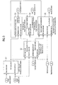
- a block diagram of a powertrain 1 ( FIG. 1 ) includes following blocks that represent on the one hand physical components and on the other hand powertrain control components (the term block is not repeated on an ongoing basis).
- a block approach algorithm 2 receives a driver input torque via a signal input E1, that is to say a drive torque desired by the driver of the motor vehicle, which leads to a corresponding propulsion of the motor vehicle. Via a signal input E2, it receives a starting characteristic that is dependent on the respective motor vehicle and other variables and will be discussed later. Block 2 evaluates these input variables and transmits, on the one hand, to a block, which represents an engine control 3 and the associated engine, a target value of the engine torque (referred to below as engine torque for short). On the other hand, it transmits to a torque model 4 of the clutch a desired value of the clutch (rotational) moments.
- the engine control 3 supplies the value of the engine speed to a clutch 6 and the actual value of the engine torque to the torque model 4. From the clutch 6 of the actual value of the clutch torque is transmitted to the other components 7 of the drive train and thus to the motor vehicle and the road. These other components gearbox, cardan shaft etc. are not shown here since they are well known and will not be changed by the invention.
- the resulting vehicle acceleration is represented as being output at an output A1.
- the torque model 4 of the clutch transmits to a clutch controller 8, which is designed either as a clutch position controller or as a clutch pressure regulator, a desired value for the position or for the pressure of the clutch. From this, the coupling controller generates a desired actuator current and transfers it to a current regulator 10. This determines from the desired actuator current and a recirculated Istaktuatorstrom an output voltage which is applied as an actuator voltage to a clutch actuator.
- a clutch controller 8 which is designed either as a clutch position controller or as a clutch pressure regulator, a desired value for the position or for the pressure of the clutch.
- the coupling controller generates a desired actuator current and transfers it to a current regulator 10. This determines from the desired actuator current and a recirculated Istaktuatorstrom an output voltage which is applied as an actuator voltage to a clutch actuator.
- the exchange of further signals and physical quantities between the components of the drive train 1 is illustrated in the drawing by connecting lines with directional arrows and also results from the following description.
- FIG. 2 illustrates the interactions and signal flows between the approach algorithm 2 and its underlying controlled system by the drive train 1 with its Aktuatorik assemblies, sensors and electronic control units, the vehicle and possibly the trailer mass, as well as the environmental influences such as the slope or slope of the road and the coefficient of friction between the tire and the road is formed.
- Input variables driver input torque, engine speed, transmission input speed, starting characteristic, actual clutch torque (optional) and actual engine torque
- Modern engine control units with e-gas usually carry out an accelerator pedal interpretation, in which the so-called driver's desired torque is calculated from the accelerator pedal position and possibly even further variables. This moment is usually related to engine and transmission input and is proportional to the desired and possible vehicle acceleration. In the event that this size should not be available, the driver's desired torque is determined as a substitute by a map interpolation, wherein input variables of the map are an accelerator pedal value in percent and the engine speed.
- the starting characteristic determines, on the one hand, the speed with which the drive torque is guided to the driver's desired torque, and, on the other hand, the engine speed level-and thus also whether the starting-up process is more fuel-efficient or rather performance-optimized. Because of these two intervention options, separate input signals for the speed of the drive torque management on the one hand and for the engine speed level on the other hand can be used instead of the combination size starting characteristic on the other hand. In the present embodiment, the use of the combination size starting characteristic is explained in detail.
- the starting characteristic can be determined continuously both in an external module of the drive train control (for example a driving strategy module) which is connected to the signal input E1 or also in the starting module itself. In the simplest case, it can also be set according to the ideas of the vehicle manufacturer.
- an external module of the drive train control for example a driving strategy module
- the start-up characteristic signal is a normalized quantity whose value can be continuously varied between a minimum value (eg 0 or 0.0%) and a maximum value (eg 1 or 1000 or 100.0%).
- This input signal allows the type of startup process depending on the situation steplessly emphasized comfortable starting with low engine speed level and thus lower clutch load with particularly easy dosing to set to a sporty acceleration with faster torque build-up and higher engine speed level.
- the actual engine torque is provided by the engine control as standard and represents the drive torque available at the clutch input (engine side).
- the actual clutch torque is the torque transmitted by the clutch. It is currently only relatively expensive to measure and is therefore determined here via a recalculation of a state variable or measured variable of the clutch (for example, the clutch position, the working pressure or the contact pressure of the clutch) using an adjustable characteristic map, with additional effects such as Temperature or the degree of wear of the clutch linings are included.
- the desired clutch torque represents the torque which can be transmitted by the starting clutch.
- This torque is converted into a manipulated variable for the clutch actuator in a manner known per se with subordinate functions which are matched to the implementation of the actuator.
- the engine setpoint torque represents the specification calculated by the approach algorithm 2 for the effective torque to be delivered by a drive train at the clutch input (engine side).
- This specification is known from the electronic engine control 3 or, in the case of additionally usable drive sources such as a hybrid vehicle, from a powertrain management system Way implemented by rules of the engine.
- the engine speed is set in the present embodiment by specifying a motor nominal torque. However, it can be set more effectively in the engine control with their special system knowledge. So if a system interface for a speed specification is available, it is appropriate to use.
- the clutch actual torque is transmitted to these, in order to enable a more exact feedforward control.
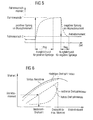
- the method for controlling a torque at startup excludes the following FIG. 3 apparent calculation steps S1 to S5 :
- driver command torque serves as the target variable for the stationary end value of the drive torque.
- the starting characteristic determines the speed of the drive torque guide. If the starting characteristic has a low value, the drive torque is rather slowly guided in the direction of the driver's desired torque and correspondingly faster in the case of large values.
- the out FIG. 5 apparent course of the drive torque is calculated with a PT1 transfer function.
- the extreme case of a jump specification is assumed here.
- For a positive jump of the driver's desired torque to a driver's request 1 results in a time to reach the steady end value, which is greater than the time at a negative jump of the driver's desired torque to a driver's request 2.
- the respective filter time constant is for both cases from different adjustable Maps - depending on the starting characteristic - read out.
- the starting function can be carried out depending on the characteristic in tendentially low speed ranges (rather consumption optimal) or tend to higher speed ranges for higher performance requirements, as long as the engine speed is still sufficient for the provision of the requested torque.
- a torque can be represented at any speed between the full-load characteristic and the maximum torque-providing speed ( FIG. 6 ).
- a low speed level is chosen and for high power a higher speed level. Accordingly, it is possible to represent different speed trajectories which, during the starting process, have a given starting characteristic in the engine map be traversed to the driver's request moment.
- a trajectory for a low and one for a high speed level and one for a medium speed level is shown.
- the engine target speed now results with the drive torque and the starting characteristic as input variables by interpolation from the associated engine speed trajectory of the engine map.
- the engine target speeds are limited by the full load characteristic and the maximum engine torque speed. Above the full load characteristic, the engine is no longer able to deliver the required engine torque.
- the engine speed thus determined is then compared to the current transmission speed to assure that no engine target speed is ever output that is less than the current transmission input speed.
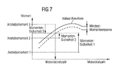
- torque safety is based on FIG. 7 explained.
- the ability of an engine to accelerate itself and thereby also the vehicle in torque-transmitting clutch depends on the reserve of available engine torque, which separates it from the full load (full load) at a given engine speed.
- full load means that the drive torque and thus the active vehicle speed can be just kept constant, or that it decreases immediately at low load (mountain, air resistance), that is, causes a speed drop, which is associated with a loss of comfort.
- the full-load characteristic curve should always be undercut by an adjustable value, thus providing a minimum torque reserve.
- speed increases with a larger torque reserve can be realized with greater dynamics.
- security moment Vollastmoment Motorist - rotation speed - Minimum torque reserve - load torque
- the capacity of the friction clutch to transmit a moment directly determines the torque present at the drive wheel in the slip region. As a rule, this moment can not be measured directly, which is why various substitute methods are conceivable for the determination.
- M motSoll M MotSoll Yorst + M MotSoll . re G
- M MotSoll Yorst ⁇ Mot ⁇ ⁇ MotSoll . current - ⁇ MotSoll . old ⁇ ⁇ T - M Kup ⁇ is
- a controller (a PID controller) is used in parallel with the precontrol, which corrects any static or dynamic feedforward control errors in block 19.
- the coincidence of the actual clutch torque with the calculated desired clutch torque is monitored in a block 20 containing a conventional PID controller.
- this function can also be realized in the engine control.
- the engine setpoint torque instead of the engine setpoint torque, the engine setpoint speed and the load torque currently acting on the engine (clutch actual torque + possibly torque for additional consumers) are then transferred to the engine control as an interface.
- step S4 a transfer function is used to estimate the actual clutch torque, a possible difference to the actual clutch torque present in block 20 is expediently checked.
- the current clutch torque is calculated from the actual engine torque and the engine speed and compared with the previously calculated actual clutch torque.
- the difference results in the necessary correction of the target specification in step S3 and is transmitted to its calculation.
- This monitoring guarantees a reproducibility of the start-up processes, even in the event of fluctuations in the system parameter properties, and makes it possible to use the detected deviation to adapt the system parameters. If the clutch actual torque is provided by an external model, this correction is expediently outside the start-up algorithm.
- the calculation of the engine speed curve with the aid of the engine map and the starting characteristic has several advantages: a minimal clutch wear and a low engine noise level due to situation-specific low engine speeds; optimized fuel consumption by using the engine map; a reduction of the friction power by an adaptable to the clutch load engine speed level; a smooth transition between a consumption and power oriented engine speed trajectory (resulting from the engine map).
- the target engine speed can be output and the estimated actual clutch torque can be output to it as a disturbance variable.
- an engine speed adjustment in the last part of the slip phase target speed increase and thus a particularly smooth transition between a slipping and a sticking state of the clutch is possible.
- the calculation of the drive torque curve including the starting characteristic results in a good starting behavior even with a troubled accelerator pedal or a stop of the starting process (for example stop-and-go drive).
- the softness of the approach is adjustable (important in winter operation, starting on the mountain, preloading of the clutch).
- the starting characteristics are adjustable according to the driver type (between soft and hard).
- the management of the engine torque as a function of the driver's desired torque and the starting characteristic makes it possible to influence the dynamics of the engine torque management in the sense of a previously defined optimum start-up.
- the engine and The coupling torque can be coordinated, and this coordinated guidance of the two torques results in a harmonious course of the drive torque taking into account the dynamics of the engine and clutch.
- the manipulated variables of the approach algorithm act on the components of the drive train and lead to a resulting vehicle acceleration.
- FIG. 10 Shown is the time course of the engine target speed (dashed line) and the transmission speed.
- FIG. 11 Shown is the time course of the driver's desired torque, the engine torque (strong dashed line) and the clutch torque (fine dashed line). Such courses are achieved by the method according to the invention.
- the engine setpoint torque is usually forwarded via the CAN bus of the vehicle to the engine or powertrain control unit and in conjunction with the internal combustion engine and optionally a starter-generator, it is converted into a coupling input-side drive torque.
- the clutch setpoint torque is determined by a hierarchically structured cascade, which is triggered by the blocks 4, 8 and 10 connected in series FIG. 1 is formed by subordinate functions in the manipulated variable for the clutch actuator.
- the target position or the target pressure of the actuator 11 is calculated and the non-linearities of the clutch torque transmission compensated.
- the non-linearities of the Kupplungslage- or clutch pressure control loop are compensated and calculated the appropriate actuator current.
- the non-linearities of the current loop are taken into account and the appropriate actuator output voltage adjusted. Only through this hierarchically structured structure of functions is it possible to precisely guide the clutch torque, which can be measured directly with great effort.
- the nominal clutch torque is converted by means of a characteristic map into a desired clutch position or a clutch pressure.
- the instantaneous actual clutch torque is also determined in this subfunction via the equation of motion of the internal combustion engine in order to correct the manipulated variable in the event of undesired deviations between desired and actual clutch torque.
- the two following functions of the cascade structure namely the clutch state controller, which is designed as a clutch position controller in the case of a dry clutch or clutch pressure regulator in the case of a wet clutch, and the current control are the subject of the following non-prepublished patent applications DE 10137581.6 respectively. DE 10211057.3 ,
Claims (8)
- Procédé de commande d'un couple de rotation qui est transmis, lors du démarrage d'un véhicule, par un moteur à la boîte de vitesses par l'intermédiaire d'un embrayage automatisé, dans lequel le régime moteur, le couple d'entraînement souhaité par le conducteur du véhicule automobile, le couple moteur réel et le régime d'entrée de la boîte de vitesses sont exploités et des signaux sont générés pour commander des valeurs de consigne pour le couple moteur (Cmot. consigne) et le couple d'embrayage (Cembrayage. consigne) , caractérisé en ce que- une caractéristique de démarrage du véhicule automobile, au moyen de laquelle est déterminée la vitesse à laquelle le couple d'entraînement est amené au couple d'entraînement souhaité par le conducteur du véhicule automobile, est en outre exploitée et utilisée pour générer les signaux de commande, et en ce que- la valeur de consigne pour le couple moteur (Cmot. consigne) est composée d'une fraction de pré-commande (Cmot. consigne , pré-com) pour compenser le couple de charge de l'embrayage et pour modifier le régime de la masse inerte du moteur et d'une fraction de réglage (C mot. consigne, régl. ) pour régler le régime moteur de consigne.
- Procédé selon la revendication 1, caractérisé en ce que la caractéristique de démarrage est établie à l'aide d'une évaluation du comportement du conducteur et des influences de l'environnement sur le véhicule automobile.
- Procédé selon la revendication 1, caractérisé en ce que le niveau de régime moteur est déterminé par la caractéristique de démarrage.
- Procédé selon la revendication 1, caractérisé en ce que la pré-commande est effectuée à l'aide de l'équation de mouvement du moteur :

- Procédé selon la revendication 1, caractérisé en ce qu'à partir du couple d'entraînement effectif et du régime réel du moteur, on calcule une réserve de couple disponible.
- Procédé selon la revendication 1, caractérisé en ce que le couple d'embrayage de consigne est déterminé sur la relation suivants :

C embrayage consigne est le couple d'embrayage de consigne,
C entraînement est le couple d'entraînement,
C réserve moteur corr . est la correction du couple de rotation en fonction de la sécurité du couple moteur, et
C embrayage corr. réel est la correction du couple de rotation en fonction de l'estimation du couple d'embrayage réel. - Procédé selon la revendication 1, caractérisé en ce qu'un couple d'embrayage réel avec une fonction de transmission de premier ou de second ordre est estimé à partir du couple d'embrayage de consigne, lorsque le comportement de l'embrayage est connu.
- Procédé selon la revendication 1, caractérisé en ce que les grandeurs de sortie de la caractéristique de démarrage sont calculées avec un système à logique floue à partir des grandeurs de départ.
Applications Claiming Priority (3)
| Application Number | Priority Date | Filing Date | Title |
|---|---|---|---|
| DE10226929 | 2002-06-17 | ||
| DE10226929 | 2002-06-17 | ||
| PCT/DE2003/001874 WO2003106211A1 (fr) | 2002-06-17 | 2003-06-03 | Procede de regulation d'un couple |
Publications (2)
| Publication Number | Publication Date |
|---|---|
| EP1513700A1 EP1513700A1 (fr) | 2005-03-16 |
| EP1513700B1 true EP1513700B1 (fr) | 2011-05-04 |
Family
ID=29723200
Family Applications (1)
| Application Number | Title | Priority Date | Filing Date |
|---|---|---|---|
| EP03759833A Expired - Fee Related EP1513700B1 (fr) | 2002-06-17 | 2003-06-03 | Procede de regulation d'un couple |
Country Status (3)
| Country | Link |
|---|---|
| EP (1) | EP1513700B1 (fr) |
| DE (1) | DE50313669D1 (fr) |
| WO (1) | WO2003106211A1 (fr) |
Cited By (1)
| Publication number | Priority date | Publication date | Assignee | Title |
|---|---|---|---|---|
| DE102013112554A1 (de) * | 2013-11-14 | 2015-05-21 | Dr. Ing. H.C. F. Porsche Aktiengesellschaft | Verfahren zum Betreiben einer Motorsteuerungseinrichtung zum Steuern eines Motors eines Kraftfahrzeugs während einer Rennstartphase und Motorsteuerungseinrichtung |
Families Citing this family (6)
| Publication number | Priority date | Publication date | Assignee | Title |
|---|---|---|---|---|
| DE102006037704A1 (de) * | 2006-08-11 | 2008-02-14 | Zf Friedrichshafen Ag | Verfahren zur fahrwiderstandsabhängigen Einstellung des Kupplungsmomentes eines Kraftfahrzeuges |
| DE102012201841B4 (de) * | 2012-02-08 | 2013-09-26 | Bayerische Motoren Werke Aktiengesellschaft | Verfahren zur Vorbereitung eines definierten, vom Fahrer anwählbaren Anfahrvorganges |
| JP2018027743A (ja) * | 2016-08-17 | 2018-02-22 | ヤマハ発動機株式会社 | 車両及びその制御方法 |
| CN109871044B (zh) * | 2019-03-19 | 2022-04-01 | 北京经纬恒润科技股份有限公司 | 一种转速跟踪方法及装置 |
| CN113442907B (zh) * | 2020-03-24 | 2023-12-01 | 广州汽车集团股份有限公司 | 一种低速工况下控制车速的方法及装置 |
| CN111625945B (zh) * | 2020-05-15 | 2023-08-04 | 安徽江淮汽车集团股份有限公司 | 电机控制系统的评价方法、装置、设备及存储介质 |
Family Cites Families (8)
| Publication number | Priority date | Publication date | Assignee | Title |
|---|---|---|---|---|
| US4874070A (en) * | 1988-02-10 | 1989-10-17 | Eaton Corporation | Control for AMT system start from stop operation |
| US4873637A (en) * | 1988-02-10 | 1989-10-10 | Eaton Corporation | Control for vehicle start from stop operation |
| JP2717253B2 (ja) * | 1988-02-16 | 1998-02-18 | 富士重工業株式会社 | 車両用自動クラッチの制御装置 |
| DE4409122C2 (de) * | 1993-08-10 | 1998-12-24 | Porsche Ag | Vorrichtung und Verfahren zum Regeln einer Kupplung eines Fahrzeugantriebes |
| EP0638742A1 (fr) * | 1993-08-12 | 1995-02-15 | Siemens Aktiengesellschaft | Régulation d'un sous-système d'un véhicule, en particulier d'une transmission automatique |
| FR2746353B1 (fr) * | 1996-03-21 | 2000-07-21 | Luk Getriebe Systeme Gmbh | Dispositif pour commander un systeme de transmission de couple |
| FR2796894B1 (fr) * | 1999-07-27 | 2001-10-26 | Renault | Dispositif de commande du demarrage d'un vehicule automobile |
| DE59906521D1 (de) * | 1999-08-24 | 2003-09-11 | Siemens Ag | Steuerung für den Antriebsstrang beim Anfahren eines Kraftfahrzeugs |
-
2003
- 2003-06-03 WO PCT/DE2003/001874 patent/WO2003106211A1/fr not_active Application Discontinuation
- 2003-06-03 DE DE50313669T patent/DE50313669D1/de not_active Expired - Lifetime
- 2003-06-03 EP EP03759833A patent/EP1513700B1/fr not_active Expired - Fee Related
Cited By (2)
| Publication number | Priority date | Publication date | Assignee | Title |
|---|---|---|---|---|
| DE102013112554A1 (de) * | 2013-11-14 | 2015-05-21 | Dr. Ing. H.C. F. Porsche Aktiengesellschaft | Verfahren zum Betreiben einer Motorsteuerungseinrichtung zum Steuern eines Motors eines Kraftfahrzeugs während einer Rennstartphase und Motorsteuerungseinrichtung |
| DE102013112554B4 (de) | 2013-11-14 | 2023-11-02 | Dr. Ing. H.C. F. Porsche Aktiengesellschaft | Verfahren zum Betreiben einer Motorsteuerungseinrichtung zum Steuern eines Motors eines Kraftfahrzeugs während einer Rennstartphase und Motorsteuerungseinrichtung |
Also Published As
| Publication number | Publication date |
|---|---|
| DE50313669D1 (de) | 2011-06-16 |
| WO2003106211A1 (fr) | 2003-12-24 |
| EP1513700A1 (fr) | 2005-03-16 |
Similar Documents
| Publication | Publication Date | Title |
|---|---|---|
| DE102014204431B4 (de) | Hybridfahrzeug mit einer drehmomentwandlerschlupfsteuerung auf der basis von motordrehmoment und einer schlupfrückkopplungssteuerung während instationärer ereignisse | |
| DE19652244B4 (de) | Verfahren zur Adaption des Greifpunktes eines Kupplungsystems | |
| DE4321413C2 (de) | Verfahren und Vorrichtung zur Steuerung der Antriebsleistung eines Fahrzeugs | |
| DE112008001208B4 (de) | Steuergerät und Steuerverfahren für eine Fahrzeugantriebseinheit | |
| DE4239711B4 (de) | Verfahren und Vorrichtung zur Steuerung eines Fahrzeugs | |
| EP1399327B1 (fr) | Procede pour commander l'ensemble transmission d'un vehicule automobile | |
| DE60223215T2 (de) | Antriebskraftsteuerung für ein Fahrzeug | |
| DE102015117563A1 (de) | Hybridantriebsstrangdrehzahlsteuerung | |
| EP0918657B1 (fr) | Systeme de regulation commune d'un servo-embrayage et d'un moteur de vehicule | |
| DE10153476A1 (de) | Drehmomentsteuerungs- bzw. -regelungssystem und Drehmomentsteuerungs- bzw. -regelungsverfahren für ein Hybridfahrzeug | |
| EP2079620B1 (fr) | Procédé pour faire fonctionner un système de propulsion hybride à configuration en parallèle | |
| AT515103B1 (de) | Verfahren zum starten einer brennkraftmaschine | |
| WO2003019029A1 (fr) | Procede et systeme de commande d'un embrayage a friction automatise dispose entre un moteur et une boite de vitesses d'un vehicule | |
| DE10148516A1 (de) | Integriertes Fahrzeugsteuersystem | |
| WO2003051663A1 (fr) | Dispositif et procede pour reguler la vitesse de roulage d'un vehicule | |
| DE2700788B2 (de) | Vorrichtung zur Einstellung des Schaltrucks in Kraftfahrzeugen | |
| DE102005022249A1 (de) | Abfangen eines Einzelmotorbetriebs für ein elektrisch verstellbares Getriebe | |
| EP2379390B1 (fr) | Procédé et dispositif pour le fonctionnement d'un véhicule hybride | |
| DE19907753A1 (de) | Motorausgangsleistungssteuereinheit | |
| DE102015225608A1 (de) | Verfahren zum automatisierten Ankriechen eines Kraftfahrzeugs | |
| DE60008154T2 (de) | Verfahren zur Bildung von Standardwiderstandswerten und Anwendung für eine Fahrzeugsteuerung | |
| DE19725816A1 (de) | Kraftfahrzeug, sowie ein Verfahren zur Verwendung eines Kraftfahrzeuges | |
| EP1513700B1 (fr) | Procede de regulation d'un couple | |
| DE102019105901B4 (de) | Schliessraten-Management des Zahnradspiels in einem Antriebsstrangsystem | |
| EP1354751B1 (fr) | Dispositif de commande du démarrage d'un véhicule automobile avec boite de vitesses |
Legal Events
| Date | Code | Title | Description |
|---|---|---|---|
| PUAI | Public reference made under article 153(3) epc to a published international application that has entered the european phase |
Free format text: ORIGINAL CODE: 0009012 |
|
| 17P | Request for examination filed |
Effective date: 20041022 |
|
| AK | Designated contracting states |
Kind code of ref document: A1 Designated state(s): AT BE BG CH CY CZ DE DK EE ES FI FR GB GR HU IE IT LI LU MC NL PT RO SE SI SK TR |
|
| 17Q | First examination report despatched |
Effective date: 20050502 |
|
| RBV | Designated contracting states (corrected) |
Designated state(s): DE FR IT |
|
| RAP1 | Party data changed (applicant data changed or rights of an application transferred) |
Owner name: CONTINENTAL AUTOMOTIVE GMBH |
|
| GRAP | Despatch of communication of intention to grant a patent |
Free format text: ORIGINAL CODE: EPIDOSNIGR1 |
|
| RIC1 | Information provided on ipc code assigned before grant |
Ipc: B60W 10/06 20060101AFI20100730BHEP Ipc: B60W 10/08 20060101ALI20100730BHEP Ipc: B60W 30/18 20060101ALI20100730BHEP |
|
| GRAS | Grant fee paid |
Free format text: ORIGINAL CODE: EPIDOSNIGR3 |
|
| GRAA | (expected) grant |
Free format text: ORIGINAL CODE: 0009210 |
|
| AK | Designated contracting states |
Kind code of ref document: B1 Designated state(s): DE FR IT |
|
| REF | Corresponds to: |
Ref document number: 50313669 Country of ref document: DE Date of ref document: 20110616 Kind code of ref document: P |
|
| REG | Reference to a national code |
Ref country code: DE Ref legal event code: R096 Ref document number: 50313669 Country of ref document: DE Effective date: 20110616 |
|
| PLBE | No opposition filed within time limit |
Free format text: ORIGINAL CODE: 0009261 |
|
| STAA | Information on the status of an ep patent application or granted ep patent |
Free format text: STATUS: NO OPPOSITION FILED WITHIN TIME LIMIT |
|
| 26N | No opposition filed |
Effective date: 20120207 |
|
| PG25 | Lapsed in a contracting state [announced via postgrant information from national office to epo] |
Ref country code: IT Free format text: LAPSE BECAUSE OF FAILURE TO SUBMIT A TRANSLATION OF THE DESCRIPTION OR TO PAY THE FEE WITHIN THE PRESCRIBED TIME-LIMIT Effective date: 20110504 |
|
| REG | Reference to a national code |
Ref country code: DE Ref legal event code: R097 Ref document number: 50313669 Country of ref document: DE Effective date: 20120207 |
|
| REG | Reference to a national code |
Ref country code: FR Ref legal event code: PLFP Year of fee payment: 14 |
|
| REG | Reference to a national code |
Ref country code: FR Ref legal event code: PLFP Year of fee payment: 15 |
|
| REG | Reference to a national code |
Ref country code: FR Ref legal event code: PLFP Year of fee payment: 16 |
|
| PGFP | Annual fee paid to national office [announced via postgrant information from national office to epo] |
Ref country code: DE Payment date: 20180630 Year of fee payment: 16 |
|
| PGFP | Annual fee paid to national office [announced via postgrant information from national office to epo] |
Ref country code: FR Payment date: 20180626 Year of fee payment: 16 |
|
| REG | Reference to a national code |
Ref country code: DE Ref legal event code: R119 Ref document number: 50313669 Country of ref document: DE |
|
| PG25 | Lapsed in a contracting state [announced via postgrant information from national office to epo] |
Ref country code: DE Free format text: LAPSE BECAUSE OF NON-PAYMENT OF DUE FEES Effective date: 20200101 |
|
| PG25 | Lapsed in a contracting state [announced via postgrant information from national office to epo] |
Ref country code: FR Free format text: LAPSE BECAUSE OF NON-PAYMENT OF DUE FEES Effective date: 20190630 |