EP1513642B1 - Schneidwerkzeugkopf für ein metallbearbeitungswerkzeug - Google Patents
Schneidwerkzeugkopf für ein metallbearbeitungswerkzeug Download PDFInfo
- Publication number
- EP1513642B1 EP1513642B1 EP03733749A EP03733749A EP1513642B1 EP 1513642 B1 EP1513642 B1 EP 1513642B1 EP 03733749 A EP03733749 A EP 03733749A EP 03733749 A EP03733749 A EP 03733749A EP 1513642 B1 EP1513642 B1 EP 1513642B1
- Authority
- EP
- European Patent Office
- Prior art keywords
- insert
- slot
- holder
- tool head
- head according
- Prior art date
- Legal status (The legal status is an assumption and is not a legal conclusion. Google has not performed a legal analysis and makes no representation as to the accuracy of the status listed.)
- Expired - Lifetime
Links
- 238000005555 metalworking Methods 0.000 title claims 2
- 238000003754 machining Methods 0.000 claims abstract description 7
- 238000005452 bending Methods 0.000 claims description 2
- 230000008878 coupling Effects 0.000 description 2
- 238000010168 coupling process Methods 0.000 description 2
- 238000005859 coupling reaction Methods 0.000 description 2
- 230000037431 insertion Effects 0.000 description 2
- 238000003780 insertion Methods 0.000 description 2
- 230000004323 axial length Effects 0.000 description 1
- 238000006073 displacement reaction Methods 0.000 description 1
- 230000000694 effects Effects 0.000 description 1
- 239000002184 metal Substances 0.000 description 1
Images
Classifications
-
- B—PERFORMING OPERATIONS; TRANSPORTING
- B23—MACHINE TOOLS; METAL-WORKING NOT OTHERWISE PROVIDED FOR
- B23B—TURNING; BORING
- B23B27/00—Tools for turning or boring machines; Tools of a similar kind in general; Accessories therefor
- B23B27/04—Cutting-off tools
-
- B—PERFORMING OPERATIONS; TRANSPORTING
- B23—MACHINE TOOLS; METAL-WORKING NOT OTHERWISE PROVIDED FOR
- B23B—TURNING; BORING
- B23B2205/00—Fixation of cutting inserts in holders
- B23B2205/02—Fixation using an elastically deformable clamping member
-
- B—PERFORMING OPERATIONS; TRANSPORTING
- B23—MACHINE TOOLS; METAL-WORKING NOT OTHERWISE PROVIDED FOR
- B23B—TURNING; BORING
- B23B2220/00—Details of turning, boring or drilling processes
- B23B2220/12—Grooving
- B23B2220/123—Producing internal grooves
-
- B—PERFORMING OPERATIONS; TRANSPORTING
- B23—MACHINE TOOLS; METAL-WORKING NOT OTHERWISE PROVIDED FOR
- B23B—TURNING; BORING
- B23B2260/00—Details of constructional elements
- B23B2260/132—Serrations
-
- Y—GENERAL TAGGING OF NEW TECHNOLOGICAL DEVELOPMENTS; GENERAL TAGGING OF CROSS-SECTIONAL TECHNOLOGIES SPANNING OVER SEVERAL SECTIONS OF THE IPC; TECHNICAL SUBJECTS COVERED BY FORMER USPC CROSS-REFERENCE ART COLLECTIONS [XRACs] AND DIGESTS
- Y10—TECHNICAL SUBJECTS COVERED BY FORMER USPC
- Y10T—TECHNICAL SUBJECTS COVERED BY FORMER US CLASSIFICATION
- Y10T407/00—Cutters, for shaping
- Y10T407/22—Cutters, for shaping including holder having seat for inserted tool
- Y10T407/2272—Cutters, for shaping including holder having seat for inserted tool with separate means to fasten tool to holder
- Y10T407/2282—Cutters, for shaping including holder having seat for inserted tool with separate means to fasten tool to holder including tool holding clamp and clamp actuator
- Y10T407/2286—Resiliently biased clamp jaw
-
- Y—GENERAL TAGGING OF NEW TECHNOLOGICAL DEVELOPMENTS; GENERAL TAGGING OF CROSS-SECTIONAL TECHNOLOGIES SPANNING OVER SEVERAL SECTIONS OF THE IPC; TECHNICAL SUBJECTS COVERED BY FORMER USPC CROSS-REFERENCE ART COLLECTIONS [XRACs] AND DIGESTS
- Y10—TECHNICAL SUBJECTS COVERED BY FORMER USPC
- Y10T—TECHNICAL SUBJECTS COVERED BY FORMER US CLASSIFICATION
- Y10T409/00—Gear cutting, milling, or planing
- Y10T409/30—Milling
- Y10T409/30084—Milling with regulation of operation by templet, card, or other replaceable information supply
- Y10T409/301176—Reproducing means
- Y10T409/301624—Duplicating means
- Y10T409/30168—Duplicating means with means for operation without manual intervention
- Y10T409/302408—Duplicating means with means for operation without manual intervention including cross-slide tool carrier
Definitions
- the present invention relates to a tool head for machining tool of the kind intended for chipbreaking machining of metal.
- the tool head comprises a basic holder and a toolholder connected therewith. More specifically this tool is intended for that type of machining referred to as parting and grooving.
- Swedish patent application 7813038-2 discloses a tool for parting and grooving wherein co-operating serrations with clamping screws are used for clamping purposes.
- the number of screws for clamping the adapter is three. This means that the activity of first disengaging three comparatively long screws and subsequently tightening them again when insert change is needed for indexing a new cutting edge is rather time consuming.
- Swedish patent application 9004032-0 discloses a cutting tool comprising an insert-provided holder blade in an insert pocket where the insert is clamped by arranging for a press means to engage at inclined angle towards a slot in the insert pocket such that an upper clamping arm portion of the holder blade is subjected to elastic bending and a force activated therefrom towards the upper surface of the insert. Due to the fact that the press means is constituted by a relatively long pin this system becomes relatively space consuming in a narrow holder blade for a parting tool.
- a tool head according to the preamble of claim 1 is disclosed in EP1025939.
- a recess for a clamping screw is provided in the cross direction of the holder, however.
- a primary object of the invention is to create a device by means of which the necessary cutting insert exchanges are effected in a quick and simple way without dismounting each clamp scrwe in its entirety.
- a further object is to create a tool that makes it possible eliminate a risk that the clamp means of that type are lost.
- Still a further object of the invention is to create a tool where during dismounting there is no need for using different key means.
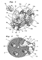
- a basic holder 1 comprising a central bore 2 for engagement witb a tool machine and 3 designated a cutting insert.
- the basic holder 1 comprises a forwards and laterally extending portion 4.
- the basic holder is intended to be engaged to a tool machine, for instance a multi-purpose lathe.
- the portion 4 extending laterally is provided as a blade-shaped portion comprising a lower insert supporting portion 6 and an integral upper clamp portion 5 with smaller width than the remainder of the basic holder 1.
- the insert's rear end surface 3 a is intended to abut against a shoulder 8 which limits its axial rear displacement
- the shoulder 8 extends from the lower support portion 6 of the lateral side portion 4. Due to this, the clamping slot 7 transforms rearwardly into a slot extension 9 with considerably smaller height than the forward slot 7.
- the endportion of the slot extension 9 is designated 9a.
- the lower surface 3b of the cutting insert preferably is oriented in a direction perpendicularly towards the rear end surface 3a of the insert and that said lower surface 3b simultaneously is parallel with the intended feed direction.
- the rear portion of the upper portion of the insert and the lower surface 3b have preferably been provided with concave V-shaped wedge-type recesses in the manner described and shown in Swedish patent application 9703434-2 the content of which is incorporated herewith.
- the basic holder is provided with a plurality of spaced cylindrical holes 10a, 10b, 10c, 10d which exetend laterally in a direction parallel with the central axis CL of the basic holder.
- a corresponding nut roll 11 that is located therein with a suitable play whereby the axial length of each nut roll is the same as the thickness of the basic holder 1 and the integral toolholder 4.
- it is intended to have three clamp screws 12, 13, 14 received in the remainder of said holes 10b, 10c, 10d to be threadably engaged in corresponding holes in suitable connecting portion in a corresponding machine (not shown).
- the recess 15 extends radially inwardly to a position between the bore 2 and the end portion 9a on the slot 9 such that a hinge 17 is provided therebetween.
- This recess is intended to receive a clamp screw with a correspondingly formed conical head 18, the lower portion of which is intended to be threadably engaged in a threaded portion 21 of the nut roll 11a.
- the tool head 1 is also provided with a laterally extending slot 20 that extends to the recess 12 which slot extends all the way through said head whilst extending centrally through said conical recess 16. From Fig. 1 it appears that the insert receiving slot7 extends laterally through both the basic holder 1 and the toolholder 4.
- the inner surface of the holder 1 is provided with a serration 22 that extends in the longitudinal direction of the insert except for the surface portion 23 that is located between the screw 19 and the slot extension 9.
- a corresponding serration is understood to be present on the machine in which the holder 1 is to be connected.
- the screw receiving recess 15 ought to extend longitudinally in a direction that is provided at an angle of 25-105° relative to the longitudinal direction of the insert pocket. This angle preferably amounts to 35-90° in order to obtain an optimal moment arm in relation to the hinge 17.
- the basic holder 1 should preferably have a width that is several times the width of the insert-receiving portion 4 wich represents the insert carrying holder portion. With the embondiment shown in Fig. 1-2 the longitudinal extent of the insert 3 should be larger than the underneath support surface 4a of the insert holder 4 as appears from Fig. 2 such that the insert obtains a side support from the basic holder 1.
Landscapes
- Engineering & Computer Science (AREA)
- Mechanical Engineering (AREA)
- Cutting Tools, Boring Holders, And Turrets (AREA)
- Knives (AREA)
- Accessories And Tools For Shearing Machines (AREA)
- Milling Processes (AREA)
Claims (8)
- Werkzeugkopf für eine Span-Metallbearbeitung mit einem Schneideinsatz (3), mit einem Grundhalter (1) und einem mit diesem verbundenen Einsatzhalter (4), dessen Vorderabschnitt mit einer Einsatztasche versehen ist, die zwischen einem unteren Stützabschnitt (6) und einem oberen Klemmabschnitt (5) angeordnet ist, wobei der obere Klemmabschnitt (5) durch eine Preßvorrichtung in Klemmflächeneingriff mit dem Schneideinsatz (3) betätigbar ist, wobei das Werkzeug mit einem Schlitz (20) versehen ist, der von der Einsatztasche im Abstand angeordnet ist, und wobei die Preßvorrichtung die Form einer Klemmschraube (19) mit einem konischen Kopf (18) hat, der in einer Ausnehmung in dem Grundhalter (1) aufgenommen und angeordnet ist, um eine Bewegung axial derart auszuüben, daß ihr konischer Kopf in den Schlitz (20) hinein eingeführt wird und nach dem Festziehen infolge ihrer Bewegung eine solche Auswärtsbiegung des oberen Abschnittes des Halters vorsieht, so daß ein Klemmen des Einsatzes erreicht wird, dadurch gekennzeichnet, daß der Schraubenmutterzylinder (11a), der für die Aufnahme der Klemmschraube (19) vorgesehen ist, in einer zylindrischen Ausnehmung (10a) aufgenommen ist, die senkrecht bezüglich der Längsrichtung der Klemmschraube (19) und der Längsrichtung des Einsatzschlitzes (7) ausgerichtet ist.
- Werkzeugkopf nach Anspruch 1, dadurch gekennzeichnet, daß der Grundhalter (1) eine größere Breite hat als der Einsatzhalter (4) und daß beide ganzheitlich in einem Stück vorgesehen sind.
- Werkzeugkopf nach Anspruch 1, dadurch gekennzeichnet, daß die die Schraube aufnehmende Ausnehmung (15) eine längliche Erstreckung unter einem Winkel hat mit einer Ausrichtung unter einem Winkel von 35 - 90° von der Längsrichtung der Einsatztasche.
- Werkzeugkopf nach einem der Ansprüche 1 bis 3, dadurch gekennzeichnet, daß der den Einsatz aufnehmende Schlitz (7) sich in der Rückwärtsrichtung in eine Schlitzerstreckung (9) mit einer geringeren Höhe als der vordere Schlitz (7) hinein streckt.
- Werkzeugkopf nach einem der Ansprüche 1 bis 4, dadurch gekennzeichnet, daß die hintere Einsatzendfläche (3a) angeordnet ist, um axial gegen eine Stützfläche (8) in dem Halter (4) zu stoßen, die sich vorzugsweise im wesentlichen senkrecht bezüglich der unteren Fläche (3b) des Einsatzes erstreckt.
- Werkzeugkopf nach einem der Ansprüche 1q bis 5, dadurch gekennzeichnet, daß die Längserstreckung des Einsatzes (3) länger ist als die Längserstreckung der unteren Stützfläche (4a) in dem Einsatzhalter, wodurch eine Seitenstütze für den Einsatz von einer Seitenfläche des Grundhalters (1) vorgesehen ist.
- Werkzeugkopf nach einem der Ansprüche 1 bis 6, dadurch gekennzeichnet, daß die Seitenfläche des Grundhalters (1) mit Riffelungen (22) versehen ist, die sich in einer Richtung parallel zu der Richtung des Einsatzes (3) erstrecken.
- Werkzeugkopf nach einem der Ansprüche 1 bis 7, dadurch gekennzeichnet, daß der Abschnitt (23), welcher zwischen der Klemmschraube (19) und der Schlitzerstreckung (9) des Grundhalters (1) angeordnet ist, eine ebene Fläche ohne Riffelungen hat.
Applications Claiming Priority (3)
| Application Number | Priority Date | Filing Date | Title |
|---|---|---|---|
| SE0201861 | 2002-06-18 | ||
| SE0201861A SE525462C2 (sv) | 2002-06-18 | 2002-06-18 | Verktygshuvud för spånavskiljande metallbearbetningsverktyg med spännskruv vilken ingängas i en mutterrulle |
| PCT/SE2003/001013 WO2003106084A1 (en) | 2002-06-18 | 2003-06-16 | Cutting tool head for a metalworking tool |
Publications (2)
| Publication Number | Publication Date |
|---|---|
| EP1513642A1 EP1513642A1 (de) | 2005-03-16 |
| EP1513642B1 true EP1513642B1 (de) | 2005-10-12 |
Family
ID=20288222
Family Applications (1)
| Application Number | Title | Priority Date | Filing Date |
|---|---|---|---|
| EP03733749A Expired - Lifetime EP1513642B1 (de) | 2002-06-18 | 2003-06-16 | Schneidwerkzeugkopf für ein metallbearbeitungswerkzeug |
Country Status (7)
| Country | Link |
|---|---|
| US (1) | US7246974B2 (de) |
| EP (1) | EP1513642B1 (de) |
| CN (1) | CN100540188C (de) |
| AT (1) | ATE306345T1 (de) |
| DE (1) | DE60301887T2 (de) |
| SE (1) | SE525462C2 (de) |
| WO (1) | WO2003106084A1 (de) |
Families Citing this family (15)
| Publication number | Priority date | Publication date | Assignee | Title |
|---|---|---|---|---|
| SE526536C2 (sv) | 2003-11-19 | 2005-10-04 | Sandvik Intellectual Property | Verktygshuvud med spännanordning i form av en mutterrulle verkande i en slits |
| DE102006059717A1 (de) * | 2006-12-18 | 2008-06-19 | Kennametal Inc. | Werkzeughalter, insbesondere für ein Stechwerkzeug sowie Schneidkörper für einen Werkzeughalter |
| JP5115148B2 (ja) * | 2007-10-30 | 2013-01-09 | 三菱マテリアル株式会社 | インサート着脱式切削工具のヘッド部材およびインサート着脱式切削工具 |
| JP5040591B2 (ja) * | 2007-10-30 | 2012-10-03 | 三菱マテリアル株式会社 | インサート着脱式切削工具のヘッド部材およびインサート着脱式切削工具 |
| JP5519703B2 (ja) * | 2009-12-14 | 2014-06-11 | 京セラ株式会社 | 切削工具用ホルダおよび切削工具、並びにそれを用いた切削加工物の製造方法 |
| US8647023B2 (en) | 2011-04-04 | 2014-02-11 | Kennametal Inc. | Clamping mechanism for slotting cutter |
| US8985913B2 (en) * | 2012-11-13 | 2015-03-24 | Iscar, Ltd. | Cutting tool holder with internal coolant passage having a compressible member |
| DE102012111240A1 (de) * | 2012-11-21 | 2014-05-22 | Hartmetall-Werkzeugfabrik Paul Horn Gmbh | Spanabhebendes Werkzeug |
| US9511421B2 (en) * | 2013-06-14 | 2016-12-06 | Kennametal Inc. | Cutting tool assembly having clamp assembly comprising a clamp and a coolant plate |
| EP3231541B1 (de) * | 2016-04-14 | 2021-08-04 | Sandvik Intellectual Property AB | Ein stirnseitig einstechender werkzeugkörper für metallzerspannung |
| US11433461B2 (en) * | 2020-06-23 | 2022-09-06 | Iscar, Ltd. | Tool adaptor having an insert receiving pocket and a fastening bore, and cutting tool assembly |
| TW202202250A (zh) * | 2020-07-02 | 2022-01-16 | 以色列商艾斯卡公司 | 具有鋸齒狀耦合部的可置換刀頭及其所使用的刀把 |
| US12109632B2 (en) * | 2021-09-22 | 2024-10-08 | Iscar, Ltd. | Tool holder with upper and lower jaws defining an insert receiving pocket and cutting tool |
| WO2023176441A1 (ja) * | 2022-03-14 | 2023-09-21 | 京セラ株式会社 | 切削工具及び切削加工物の製造方法 |
| US11904393B1 (en) * | 2022-08-18 | 2024-02-20 | Iscar, Ltd. | External grooving insert holder having upper and lower jaws connected by angled hinge portion with cooling channel extending through hinge portion, and cutting tool |
Family Cites Families (15)
| Publication number | Priority date | Publication date | Assignee | Title |
|---|---|---|---|---|
| US3775818A (en) | 1972-09-14 | 1973-12-04 | F Sirola | Tool holder with cutter clamping means |
| CH608400A5 (de) | 1977-12-31 | 1979-01-15 | Muellheim Ag Utilis | |
| DE3301919A1 (de) * | 1983-01-21 | 1984-07-26 | Werner 6967 Buchen Keller | Vorrichtung zur klemmenden befestigung von schneideinsaetzen |
| DE3635193A1 (de) | 1986-09-10 | 1988-03-24 | Reika Werk Gmbh Maschf | Schneidwerkzeug zur spanabhebenden metallbearbeitung wie stechen, anfasen, plandrehen und fraesen |
| IL91574A (en) * | 1989-09-08 | 1992-02-16 | Iscar Ltd | Cutting tool system having an exchangeable adaptor |
| SE9004032L (sv) * | 1990-12-18 | 1992-06-19 | Sandvik Ab | Skaerverktyg |
| CH688794A5 (fr) * | 1993-10-25 | 1998-03-31 | Stellram Sa | Outil de coupe à plaquettes amovibles. |
| IL115544A (en) * | 1995-10-06 | 1998-12-06 | Iscar Ltd | Cutting tool system with replaceable adapter |
| SE511934C2 (sv) | 1997-09-24 | 1999-12-20 | Sandvik Ab | Verktyg för spånavskiljande bearbetning |
| US5921724A (en) * | 1997-12-18 | 1999-07-13 | Kennametal Inc. | Insert and toolholder for machining operations |
| US6168704B1 (en) * | 1999-02-04 | 2001-01-02 | Advanced Micro Device, Inc. | Site-selective electrochemical deposition of copper |
| SE516973C2 (sv) | 1999-02-04 | 2002-03-26 | Sandvik Ab | Verktyg för avstickning och spårsvarvning försett med tandade kopplingsytor |
| US6186704B1 (en) | 1999-03-04 | 2001-02-13 | Kennametal Inc. | Toolholder with detachable blade |
| DE20017747U1 (de) | 2000-10-16 | 2000-12-28 | Holler, Karl-Heinz, 61203 Reichelsheim | Drehend antreibbares Schneidwerkzeug, insbesondere zum Fräsen oder Sägen |
| SE526536C2 (sv) | 2003-11-19 | 2005-10-04 | Sandvik Intellectual Property | Verktygshuvud med spännanordning i form av en mutterrulle verkande i en slits |
-
2002
- 2002-06-18 SE SE0201861A patent/SE525462C2/sv not_active IP Right Cessation
-
2003
- 2003-06-16 US US10/518,235 patent/US7246974B2/en not_active Expired - Fee Related
- 2003-06-16 CN CN03814454.9A patent/CN100540188C/zh not_active Expired - Fee Related
- 2003-06-16 EP EP03733749A patent/EP1513642B1/de not_active Expired - Lifetime
- 2003-06-16 AT AT03733749T patent/ATE306345T1/de not_active IP Right Cessation
- 2003-06-16 WO PCT/SE2003/001013 patent/WO2003106084A1/en not_active Ceased
- 2003-06-16 DE DE60301887T patent/DE60301887T2/de not_active Expired - Lifetime
Also Published As
| Publication number | Publication date |
|---|---|
| SE0201861D0 (sv) | 2002-06-18 |
| EP1513642A1 (de) | 2005-03-16 |
| US7246974B2 (en) | 2007-07-24 |
| US20050207853A1 (en) | 2005-09-22 |
| WO2003106084A1 (en) | 2003-12-24 |
| ATE306345T1 (de) | 2005-10-15 |
| CN1684788A (zh) | 2005-10-19 |
| DE60301887T2 (de) | 2006-07-20 |
| CN100540188C (zh) | 2009-09-16 |
| SE525462C2 (sv) | 2005-02-22 |
| DE60301887D1 (de) | 2005-11-17 |
| SE0201861L (sv) | 2003-12-19 |
Similar Documents
| Publication | Publication Date | Title |
|---|---|---|
| EP1513642B1 (de) | Schneidwerkzeugkopf für ein metallbearbeitungswerkzeug | |
| EP1025939B1 (de) | Ein- und Abstechwerkzeug | |
| EP1159101B1 (de) | Werkzeughalter mit ersetzbarem einsatzträger | |
| EP1533056B1 (de) | Schneidwerkzeugkopf für ein Metallbearbeitungswerkzeug | |
| EP1261449B1 (de) | Werkzeug und werkzeughalter mit schrägen zusammenbauflächen zwischen halter und werkzeugteil | |
| EP1013364B1 (de) | Schneidwerkzeugzusammenbau | |
| CN115697598B (zh) | 具有刀片接收凹穴和紧固开孔的工具适配器以及切削工具组件 | |
| CA3025207C (en) | Holder for a tool for material-removing machining, in particular for a longitudinal turning tool | |
| EP1287929B1 (de) | Schneidwerkzeug zur spanabhebenden Bearbeitung | |
| EP0960676B1 (de) | Werkzeug und Spanner für spannabhebende Arbeitung | |
| EP2498937B1 (de) | Schneidwerkzeuganordnung | |
| EP0949031B1 (de) | Werkzeug zur spanabhebenden Bearbeitung | |
| EP3941669B1 (de) | Einsatzhalter für einen quer ausgerichteten einsatz, schneidwerkzeug und schneideinsatz | |
| US6582163B2 (en) | Cutting insert and holders therefor | |
| KR100977695B1 (ko) | 금속가공 공구용 절삭 공구 헤드 | |
| RU2827184C1 (ru) | Адаптер для инструмента, имеющий гнездо для приема режущей пластины и крепежное отверстие, и узел режущего инструмента | |
| HK40081018A (en) | Tool adaptor having an insert receiving pocket and a fastening bore, and cutting tool assembly | |
| AU709407B2 (en) | Cutting tool assembly | |
| HK40083282A (en) | Replaceable tool head having serrated coupling portions and a tool holder therefor |
Legal Events
| Date | Code | Title | Description |
|---|---|---|---|
| PUAI | Public reference made under article 153(3) epc to a published international application that has entered the european phase |
Free format text: ORIGINAL CODE: 0009012 |
|
| 17P | Request for examination filed |
Effective date: 20041208 |
|
| AK | Designated contracting states |
Kind code of ref document: A1 Designated state(s): AT BE BG CH CY CZ DE DK EE ES FI FR GB GR HU IE IT LI LU MC NL PT RO SE SI SK TR |
|
| GRAP | Despatch of communication of intention to grant a patent |
Free format text: ORIGINAL CODE: EPIDOSNIGR1 |
|
| RIN1 | Information on inventor provided before grant (corrected) |
Inventor name: BERMINGE, ERIK Inventor name: HANSSON, PER Inventor name: OLSSON, HELENA |
|
| RAP1 | Party data changed (applicant data changed or rights of an application transferred) |
Owner name: SANDVIK INTELLECTUAL PROPERTY HB |
|
| GRAS | Grant fee paid |
Free format text: ORIGINAL CODE: EPIDOSNIGR3 |
|
| GRAA | (expected) grant |
Free format text: ORIGINAL CODE: 0009210 |
|
| RAP1 | Party data changed (applicant data changed or rights of an application transferred) |
Owner name: SANDVIK INTELLECTUAL PROPERTY AB |
|
| AK | Designated contracting states |
Kind code of ref document: B1 Designated state(s): AT BE BG CH CY CZ DE DK EE ES FI FR GB GR HU IE IT LI LU MC NL PT RO SE SI SK TR |
|
| PG25 | Lapsed in a contracting state [announced via postgrant information from national office to epo] |
Ref country code: AT Free format text: LAPSE BECAUSE OF FAILURE TO SUBMIT A TRANSLATION OF THE DESCRIPTION OR TO PAY THE FEE WITHIN THE PRESCRIBED TIME-LIMIT Effective date: 20051012 Ref country code: RO Free format text: LAPSE BECAUSE OF FAILURE TO SUBMIT A TRANSLATION OF THE DESCRIPTION OR TO PAY THE FEE WITHIN THE PRESCRIBED TIME-LIMIT Effective date: 20051012 Ref country code: IT Free format text: LAPSE BECAUSE OF FAILURE TO SUBMIT A TRANSLATION OF THE DESCRIPTION OR TO PAY THE FEE WITHIN THE PRESCRIBED TIME-LIMIT;WARNING: LAPSES OF ITALIAN PATENTS WITH EFFECTIVE DATE BEFORE 2007 MAY HAVE OCCURRED AT ANY TIME BEFORE 2007. THE CORRECT EFFECTIVE DATE MAY BE DIFFERENT FROM THE ONE RECORDED. Effective date: 20051012 Ref country code: LI Free format text: LAPSE BECAUSE OF FAILURE TO SUBMIT A TRANSLATION OF THE DESCRIPTION OR TO PAY THE FEE WITHIN THE PRESCRIBED TIME-LIMIT Effective date: 20051012 Ref country code: CZ Free format text: LAPSE BECAUSE OF FAILURE TO SUBMIT A TRANSLATION OF THE DESCRIPTION OR TO PAY THE FEE WITHIN THE PRESCRIBED TIME-LIMIT Effective date: 20051012 Ref country code: CH Free format text: LAPSE BECAUSE OF FAILURE TO SUBMIT A TRANSLATION OF THE DESCRIPTION OR TO PAY THE FEE WITHIN THE PRESCRIBED TIME-LIMIT Effective date: 20051012 Ref country code: NL Free format text: LAPSE BECAUSE OF FAILURE TO SUBMIT A TRANSLATION OF THE DESCRIPTION OR TO PAY THE FEE WITHIN THE PRESCRIBED TIME-LIMIT Effective date: 20051012 Ref country code: SI Free format text: LAPSE BECAUSE OF FAILURE TO SUBMIT A TRANSLATION OF THE DESCRIPTION OR TO PAY THE FEE WITHIN THE PRESCRIBED TIME-LIMIT Effective date: 20051012 Ref country code: BE Free format text: LAPSE BECAUSE OF FAILURE TO SUBMIT A TRANSLATION OF THE DESCRIPTION OR TO PAY THE FEE WITHIN THE PRESCRIBED TIME-LIMIT Effective date: 20051012 Ref country code: SK Free format text: LAPSE BECAUSE OF FAILURE TO SUBMIT A TRANSLATION OF THE DESCRIPTION OR TO PAY THE FEE WITHIN THE PRESCRIBED TIME-LIMIT Effective date: 20051012 Ref country code: FI Free format text: LAPSE BECAUSE OF FAILURE TO SUBMIT A TRANSLATION OF THE DESCRIPTION OR TO PAY THE FEE WITHIN THE PRESCRIBED TIME-LIMIT Effective date: 20051012 |
|
| REG | Reference to a national code |
Ref country code: GB Ref legal event code: FG4D |
|
| REG | Reference to a national code |
Ref country code: CH Ref legal event code: EP |
|
| REG | Reference to a national code |
Ref country code: IE Ref legal event code: FG4D |
|
| REF | Corresponds to: |
Ref document number: 60301887 Country of ref document: DE Date of ref document: 20051117 Kind code of ref document: P |
|
| PG25 | Lapsed in a contracting state [announced via postgrant information from national office to epo] |
Ref country code: DK Free format text: LAPSE BECAUSE OF FAILURE TO SUBMIT A TRANSLATION OF THE DESCRIPTION OR TO PAY THE FEE WITHIN THE PRESCRIBED TIME-LIMIT Effective date: 20060112 Ref country code: GR Free format text: LAPSE BECAUSE OF FAILURE TO SUBMIT A TRANSLATION OF THE DESCRIPTION OR TO PAY THE FEE WITHIN THE PRESCRIBED TIME-LIMIT Effective date: 20060112 Ref country code: SE Free format text: LAPSE BECAUSE OF FAILURE TO SUBMIT A TRANSLATION OF THE DESCRIPTION OR TO PAY THE FEE WITHIN THE PRESCRIBED TIME-LIMIT Effective date: 20060112 Ref country code: BG Free format text: LAPSE BECAUSE OF FAILURE TO SUBMIT A TRANSLATION OF THE DESCRIPTION OR TO PAY THE FEE WITHIN THE PRESCRIBED TIME-LIMIT Effective date: 20060112 |
|
| PG25 | Lapsed in a contracting state [announced via postgrant information from national office to epo] |
Ref country code: ES Free format text: LAPSE BECAUSE OF FAILURE TO SUBMIT A TRANSLATION OF THE DESCRIPTION OR TO PAY THE FEE WITHIN THE PRESCRIBED TIME-LIMIT Effective date: 20060123 |
|
| PG25 | Lapsed in a contracting state [announced via postgrant information from national office to epo] |
Ref country code: PT Free format text: LAPSE BECAUSE OF FAILURE TO SUBMIT A TRANSLATION OF THE DESCRIPTION OR TO PAY THE FEE WITHIN THE PRESCRIBED TIME-LIMIT Effective date: 20060313 |
|
| NLV1 | Nl: lapsed or annulled due to failure to fulfill the requirements of art. 29p and 29m of the patents act | ||
| PG25 | Lapsed in a contracting state [announced via postgrant information from national office to epo] |
Ref country code: HU Free format text: LAPSE BECAUSE OF FAILURE TO SUBMIT A TRANSLATION OF THE DESCRIPTION OR TO PAY THE FEE WITHIN THE PRESCRIBED TIME-LIMIT Effective date: 20060413 |
|
| REG | Reference to a national code |
Ref country code: CH Ref legal event code: PL |
|
| ET | Fr: translation filed | ||
| PG25 | Lapsed in a contracting state [announced via postgrant information from national office to epo] |
Ref country code: IE Free format text: LAPSE BECAUSE OF NON-PAYMENT OF DUE FEES Effective date: 20060616 |
|
| PG25 | Lapsed in a contracting state [announced via postgrant information from national office to epo] |
Ref country code: MC Free format text: LAPSE BECAUSE OF NON-PAYMENT OF DUE FEES Effective date: 20060630 |
|
| PLBE | No opposition filed within time limit |
Free format text: ORIGINAL CODE: 0009261 |
|
| STAA | Information on the status of an ep patent application or granted ep patent |
Free format text: STATUS: NO OPPOSITION FILED WITHIN TIME LIMIT |
|
| 26N | No opposition filed |
Effective date: 20060713 |
|
| REG | Reference to a national code |
Ref country code: IE Ref legal event code: MM4A |
|
| PG25 | Lapsed in a contracting state [announced via postgrant information from national office to epo] |
Ref country code: EE Free format text: LAPSE BECAUSE OF FAILURE TO SUBMIT A TRANSLATION OF THE DESCRIPTION OR TO PAY THE FEE WITHIN THE PRESCRIBED TIME-LIMIT Effective date: 20051012 |
|
| PG25 | Lapsed in a contracting state [announced via postgrant information from national office to epo] |
Ref country code: LU Free format text: LAPSE BECAUSE OF NON-PAYMENT OF DUE FEES Effective date: 20060616 Ref country code: TR Free format text: LAPSE BECAUSE OF FAILURE TO SUBMIT A TRANSLATION OF THE DESCRIPTION OR TO PAY THE FEE WITHIN THE PRESCRIBED TIME-LIMIT Effective date: 20051012 |
|
| PG25 | Lapsed in a contracting state [announced via postgrant information from national office to epo] |
Ref country code: CY Free format text: LAPSE BECAUSE OF FAILURE TO SUBMIT A TRANSLATION OF THE DESCRIPTION OR TO PAY THE FEE WITHIN THE PRESCRIBED TIME-LIMIT Effective date: 20051012 |
|
| REG | Reference to a national code |
Ref country code: FR Ref legal event code: PLFP Year of fee payment: 14 |
|
| REG | Reference to a national code |
Ref country code: FR Ref legal event code: PLFP Year of fee payment: 15 |
|
| PGFP | Annual fee paid to national office [announced via postgrant information from national office to epo] |
Ref country code: FR Payment date: 20170511 Year of fee payment: 15 Ref country code: DE Payment date: 20170613 Year of fee payment: 15 Ref country code: GB Payment date: 20170614 Year of fee payment: 15 |
|
| REG | Reference to a national code |
Ref country code: DE Ref legal event code: R119 Ref document number: 60301887 Country of ref document: DE |
|
| GBPC | Gb: european patent ceased through non-payment of renewal fee |
Effective date: 20180616 |
|
| PG25 | Lapsed in a contracting state [announced via postgrant information from national office to epo] |
Ref country code: GB Free format text: LAPSE BECAUSE OF NON-PAYMENT OF DUE FEES Effective date: 20180616 Ref country code: DE Free format text: LAPSE BECAUSE OF NON-PAYMENT OF DUE FEES Effective date: 20190101 Ref country code: FR Free format text: LAPSE BECAUSE OF NON-PAYMENT OF DUE FEES Effective date: 20180630 |