EP3941669B1 - Einsatzhalter für einen quer ausgerichteten einsatz, schneidwerkzeug und schneideinsatz - Google Patents
Einsatzhalter für einen quer ausgerichteten einsatz, schneidwerkzeug und schneideinsatz Download PDFInfo
- Publication number
- EP3941669B1 EP3941669B1 EP20713385.1A EP20713385A EP3941669B1 EP 3941669 B1 EP3941669 B1 EP 3941669B1 EP 20713385 A EP20713385 A EP 20713385A EP 3941669 B1 EP3941669 B1 EP 3941669B1
- Authority
- EP
- European Patent Office
- Prior art keywords
- insert
- holder
- longitudinal axis
- cutting
- Prior art date
- Legal status (The legal status is an assumption and is not a legal conclusion. Google has not performed a legal analysis and makes no representation as to the accuracy of the status listed.)
- Active
Links
Images


Classifications
-
- B—PERFORMING OPERATIONS; TRANSPORTING
- B23—MACHINE TOOLS; METAL-WORKING NOT OTHERWISE PROVIDED FOR
- B23B—TURNING; BORING
- B23B29/00—Holders for non-rotary cutting tools; Boring bars or boring heads; Accessories for tool holders
- B23B29/04—Tool holders for a single cutting tool
- B23B29/043—Tool holders for a single cutting tool with cutting-off, grooving or profile cutting tools, i.e. blade- or disc-like main cutting parts
-
- B—PERFORMING OPERATIONS; TRANSPORTING
- B23—MACHINE TOOLS; METAL-WORKING NOT OTHERWISE PROVIDED FOR
- B23B—TURNING; BORING
- B23B29/00—Holders for non-rotary cutting tools; Boring bars or boring heads; Accessories for tool holders
- B23B29/02—Boring bars
- B23B29/025—Boring toolholders fixed on the boring bar
-
- B—PERFORMING OPERATIONS; TRANSPORTING
- B23—MACHINE TOOLS; METAL-WORKING NOT OTHERWISE PROVIDED FOR
- B23C—MILLING
- B23C5/00—Milling-cutters
- B23C5/16—Milling-cutters characterised by physical features other than shape
- B23C5/20—Milling-cutters characterised by physical features other than shape with removable cutter bits or teeth or cutting inserts
- B23C5/22—Securing arrangements for bits or teeth or cutting inserts
- B23C5/2204—Securing arrangements for bits or teeth or cutting inserts with cutting inserts clamped against the walls of the recess in the cutter body by a clamping member acting upon the wall of a hole in the insert
- B23C5/2208—Securing arrangements for bits or teeth or cutting inserts with cutting inserts clamped against the walls of the recess in the cutter body by a clamping member acting upon the wall of a hole in the insert for plate-like cutting inserts
- B23C5/2213—Securing arrangements for bits or teeth or cutting inserts with cutting inserts clamped against the walls of the recess in the cutter body by a clamping member acting upon the wall of a hole in the insert for plate-like cutting inserts having a special shape
-
- B—PERFORMING OPERATIONS; TRANSPORTING
- B23—MACHINE TOOLS; METAL-WORKING NOT OTHERWISE PROVIDED FOR
- B23B—TURNING; BORING
- B23B2200/00—Details of cutting inserts
- B23B2200/08—Rake or top surfaces
- B23B2200/082—Rake or top surfaces with elevated clamping surface
-
- B—PERFORMING OPERATIONS; TRANSPORTING
- B23—MACHINE TOOLS; METAL-WORKING NOT OTHERWISE PROVIDED FOR
- B23B—TURNING; BORING
- B23B2200/00—Details of cutting inserts
- B23B2200/08—Rake or top surfaces
- B23B2200/085—Rake or top surfaces discontinuous
-
- B—PERFORMING OPERATIONS; TRANSPORTING
- B23—MACHINE TOOLS; METAL-WORKING NOT OTHERWISE PROVIDED FOR
- B23B—TURNING; BORING
- B23B2200/00—Details of cutting inserts
- B23B2200/16—Supporting or bottom surfaces
- B23B2200/163—Supporting or bottom surfaces discontinuous
-
- B—PERFORMING OPERATIONS; TRANSPORTING
- B23—MACHINE TOOLS; METAL-WORKING NOT OTHERWISE PROVIDED FOR
- B23B—TURNING; BORING
- B23B2205/00—Fixation of cutting inserts in holders
- B23B2205/02—Fixation using an elastically deformable clamping member
-
- B—PERFORMING OPERATIONS; TRANSPORTING
- B23—MACHINE TOOLS; METAL-WORKING NOT OTHERWISE PROVIDED FOR
- B23B—TURNING; BORING
- B23B2220/00—Details of turning, boring or drilling processes
- B23B2220/12—Grooving
- B23B2220/123—Producing internal grooves
-
- B—PERFORMING OPERATIONS; TRANSPORTING
- B23—MACHINE TOOLS; METAL-WORKING NOT OTHERWISE PROVIDED FOR
- B23C—MILLING
- B23C2200/00—Details of milling cutting inserts
- B23C2200/04—Overall shape
- B23C2200/0472—Trapezium
-
- B—PERFORMING OPERATIONS; TRANSPORTING
- B23—MACHINE TOOLS; METAL-WORKING NOT OTHERWISE PROVIDED FOR
- B23C—MILLING
- B23C5/00—Milling-cutters
- B23C5/02—Milling-cutters characterised by the shape of the cutter
- B23C5/10—Shank-type cutters, i.e. with an integral shaft
- B23C5/109—Shank-type cutters, i.e. with an integral shaft with removable cutting inserts
Definitions
- the subject matter of the present application relates to cutting tools, and in particular to cutting tools designed for internal cutting operations on a workpiece, of the type in which a cutting insert is releasably clamped in a transversely oriented insert receiving pocket provided on an insert holder.
- EP 0 477 480 A2 discloses an elongated insert holder according to the preamble of claim 1.
- DE 20 2009 014789 U1 discloses a cutting insert according to the preamble of claim 15.
- Cutting tools for internal cutting operations on a workpiece can include an insert holder, and a cutting insert releasably clamped in a transversely oriented insert receiving pocket.
- the insert holder can include upper and lower jaws spaced apart by a clamping recess with the insert receiving pocket located in the clamping recess.
- the insert receiving pocket can include a pocket stopper surface for positioning the cutting insert in a predefined position when inserting the cutting insert into the insert receiving pocket.
- the pocket stopper surface is formed on a stopper support portion located behind the pocket stopper surface to provide strength and rigidity to the pocket stopper surface.
- a first aspect of the present invention relating to a tool holder is defined in claim 1.
- a cutting tool as defined in claim 9 comprising:
- a third aspect of the present invention relating to a cutting insert is defined in claim 15.
- the pocket stopper surface can slope towards the pocket longitudinal plane in a direction away from the pocket front opening.
- the pocket upper clamping surface can slope towards the pocket longitudinal plane in a direction away from the pocket front opening.
- the pocket stopper surface can slope more steeply than the pocket upper clamping surface.
- the insert receiving pocket can be oriented along a transverse pocket plane which contains the pocket longitudinal axis, and which intersects the pocket upper and lower surfaces.
- the transverse pocket plane can be transverse to the holder longitudinal axis.
- the transverse pocket plane can be perpendicular to the holder longitudinal axis.
- the pocket longitudinal plane can be perpendicular to the transverse pocket plane.
- the pocket lower clamping surface can slope away from the pocket longitudinal plane in the rearward direction.
- the pocket lower clamping surface can extend longitudinally between the first and second recess side openings in a direction parallel to the pocket longitudinal axis.
- the pocket lower clamping surface can be planar.
- the pocket lower clamping surface can comprise two pocket lower clamping sub-surfaces which can be co-planar and spaced apart from each other in a direction away from the pocket front opening by a lower relief recess recessed in the pocket lower surface.
- the pocket upper clamping surface can be planar.
- the insert receiving pocket can comprise an insertion groove recessed in the pocket upper clamping surface and extending away from the pocket front opening.
- the insertion groove can extend centrally along an entire longitudinal extent of the pocket upper clamping surface so that the pocket upper clamping surface can comprise two pocket upper clamping sub-surfaces which can be co-planar and spaced apart from each other in a direction away from the holder end surface by the insertion groove.
- the pocket stopper surface can be planar.
- the insert receiving pocket can open out to the holder end surface.
- the insert receiving pocket can extend to the second recess side opening to define a pocket rear opening opposite the pocket front opening.
- the insert holder can comprise a lower support rib which protrudes from the holder peripheral surface and is located on the lower jaw adjacent the pocket front opening.
- the upper jaw can be configured to resiliently clamp a cutting insert in the insert receiving pocket without the use of an additional, separate clamping device.
- the insert holder can comprise a resilience slot formed in the clamping recess and extending rearwardly from the insert receiving pocket.
- the resilience slot can be entirely spaced apart from the holder end surface by the insert receiving pocket.
- the clamping recess can be defined by opposite recess upper and lower surfaces formed on the upper and lower jaws, respectively.
- the upper jaw can comprise an inner flexibility groove recessed in the recess upper surface.
- the inner flexibility groove can open out to the holder end surface at an inner flexibility groove opening and can extend to beyond the insert receiving pocket in the rearward direction of the insert holder.
- the pocket upper clamping surface and the pocket stopper surface can be spaced apart from each other by the inner flexibility groove.
- the upper jaw can comprise an outer flexibility groove recessed in the holder peripheral surface.
- the outer flexibility groove can open out to the holder end surface at an outer flexibility groove opening and can extend to beyond the insert receiving pocket in the rearward direction of the insert holder.
- the outer flexibility groove opening can be further from the pocket front opening than the pocket stopper surface.
- the outer flexibility groove can be oriented parallel to the holder longitudinal axis.
- the insert receiving pocket can comprise at least one pocket axial abutment surface formed on the lower jaw which delimits the insert receiving pocket in the rearward direction of the insert holder.
- the at least one pocket axial abutment surface can be spaced apart from the pocket lower clamping surface.
- the lower jaw can comprise two pocket axial abutment surfaces which can be spaced apart from each other in a direction away from the pocket lower clamping surface by an axial relief recess.
- the shank portion and the insert mounting portion can be integrally formed together to have unitary one-piece construction.
- the holder peripheral surface at the insert mounting portion can be convexly curved.
- Each insert stopper surface can slope towards the insert median plane in a direction towards the associated cutting edge.
- Each insert upper abutment surface can slope towards the insert median plane in a direction towards the associated cutting edge.
- the insert stopper surface can slope more steeply than the insert upper abutment surface.
- the cutting insert can be resiliently clamped in the insert receiving pocket.
- the cutting edge that is proximate the pocket front opening can form an active cutting edge.
- the pocket stopper surface can abut the insert stopper surface.
- the pocket lower clamping surface can abut one of the at least one insert lower abutment surfaces.
- the pocket upper clamping surface abuts the insert upper abutment surface that is furthest from the active cutting edge.
- the insert receiving pocket can comprise at least one forwardly facing pocket axial abutment surface formed on the lower jaw for delimiting the insert receiving pocket in the rearward direction.
- Each insert side surface can comprise an insert side abutment surface.
- the at least one pocket axial abutment surface can abut one of the insert side surfaces.
- the mounting projection can extend between the two insert side surfaces.
- the mounting projection can be spaced apart from the two rake surfaces, in a direction along the insert longitudinal axis.
- Each insert stopper surface can be planar.
- Each insert upper abutment surface can be planar.
- the cutting insert can have an insert central axis perpendicular to, and intersecting with, the insert longitudinal axis, and intersecting the insert upper and lower surfaces.
- the cutting insert can exhibit rotational symmetry about the insert central axis.
- the at least one insert lower abutment surface can extend parallel to the insert longitudinal axis.
- the cutting insert can be devoid of a through hole, for a retaining screw.
- the at least one insert lower abutment surface can be planar.
- the cutting insert can have an insert central axis perpendicular to, and intersecting with, the insert longitudinal axis, and intersecting the insert upper and lower surfaces.
- the insert lower surface can comprise two insert lower abutment surface which can be planar and slope towards the insert central axis in a direction away from the insert upper surface.
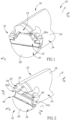
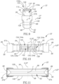
- FIG. 1 showing a cutting tool 20, for chip removal, in accordance with embodiments of the subj ect matter of the present application.
- the cutting tool 20 has a cutting insert 22 which can be typically made from cemented carbide.
- the cutting tool 20 also has an insert holder 24 which can be typically made from steel.
- the cutting tool 20 is an internal grooving tool and the cutting insert 22 is a grooving insert.
- the cutting tool 20 is adjustable between a released and fastened position. In the fastened position of the cutting tool 20, the cutting insert 22 is releasably attached to the insert holder 24.
- the insert holder 24 is elongated along a holder longitudinal axis B that defines opposite forward to rearward direction D F , D R .
- the insert holder 24 includes a holder peripheral surface 26 that extends circumferentially along the holder longitudinal axis B.
- the holder peripheral surface 26 intersects, and forms a boundary of, a holder end surface 28 at a forward end of the insert holder 24.
- the holder longitudinal axis B can intersect the holder end surface 28.
- the insert holder 24 includes a shank portion 30 and an insert mounting portion 32 located at a forward end thereof. Both the shank portion 30 and the insert mounting portion 32 are defined circumferentially by the holder peripheral surface 26.
- the shank portion 30 and the insert mounting portion 32 can be integrally formed together to have unitary one-piece construction. That is to say, the tool holder is devoid of a separate adaptor of the type disclosed in US 5,833,403 .
- the holder peripheral surface 26 at the insert mounting portion 32 can be convexly curved.
- the holder peripheral surface 26 can have an elliptical cross-section taken in a plane perpendicular to the holder longitudinal axis B. This aids insertion of the cutting tool 20 into round holes.
- the holder peripheral surface 26 at the shank portion 30 can be convexly curved. It is noted that the insert holder 24 is not in the form of a blade, as known in the art (e.g. as also disclosed in US 9,033,622 ), and which are suitable for external grooving.
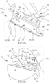
- the insert mounting portion 32 includes an upper jaw 34 and a lower jaw 36.
- the upper and lower jaws 34, 36 can be integrally formed together to have unitary one-piece construction.
- the upper and lower jaws 34, 36 are spaced apart by a clamping recess 38.
- the clamping recess 38 is recessed in the holder end surface 28.
- the clamping recess 38 extends on the holder end surface 28 to two distinct portions of the holder peripheral surface 26.
- the clamping recess 38 includes first and second recess side openings 40a, 40b at which the clamping recess 38 opens out to the holder peripheral surface 26.
- the first and second recess side openings 40a, 40b are on opposite sides of the holder peripheral surface 26 along a pocket longitudinal axis L. It is noted that the first and recess second side openings 40a, 40b intersect the holder end surface 28.
- the clamping recess 38 can be defined by opposite recess upper and lower surfaces 42, 44 formed on the upper and lower jaws, respectively 34, 36.
- the recess upper and lower surfaces 42, 44 connect the first and second recess side openings 40a, 40b and extend to the holder end surface 28.
- the upper jaw 34 is movable with respect to the lower jaw 36 by rotating around a pivot axis P.
- the pivot axis P is non-parallel to the holder longitudinal axis B.
- the pivot axis P can be perpendicular to the holder longitudinal axis B.
- the upper jaw 34 can be resiliently movable with respect to the lower jaw 36.
- the upper jaw 34 can be configured to resiliently clamp the cutting insert 22 without the use of an additional, separate clamping device, such as a clamping screw or other fastener.
- the insert mounting portion 32 includes a transversely oriented insert receiving pocket 46, which has an insert insertion direction Di that is transverse to the holder longitudinal axis B.
- the insert receiving pocket 46 is configured to receive a cutting insert 22 therein.
- the insert receiving pocket 46 is formed in the clamping recess 38. More specifically, the insert receiving pocket 46 is defined, at least partially, by pocket upper and lower surfaces 48, 50 formed on the upper and lower jaws 34, 36, respectively. Even more specifically, the pocket upper and lower surfaces 48, 50 are located on the recess upper and lower surfaces 42, 44, respectively.
- the insert receiving pocket 46 extends longitudinally along the pocket longitudinal axis L to the first recess side opening 40a to define a pocket front opening 52a.
- the pocket front opening 52a is of sufficient dimensions to allow insertion of the cutting insert 22 into the insert receiving pocket 46.
- the pocket longitudinal axis L passes between the pocket upper and lower surfaces 48, 50 and passes through the pocket front opening 52a.
- the pocket longitudinal axis L defines opposite insert insertion and extraction directions D I , D E .
- the insert receiving pocket 46 extends to the second recess side opening 40b to define a pocket rear opening 52b opposite the pocket front opening 52a.
- the pocket longitudinal axis L passes through the pocket rear opening 52b.
- the insert receiving pocket 46 can open out to the holder end surface 28. Stated differently, the insert receiving pocket 46 can be immediately adjacent to (i.e., adjoin) the holder end surface 28.
- the insert receiving pocket 46 can be in the basic form of a clamping slot, suitable for receiving elongated grooving inserts of the type known in the art (e.g. as disclosed in US 5,833,403 ), which permit internal grooving of the workpiece to be performed.
- the insert holder 24 may have only a single insert receiving pocket 46, rather than having two or more circumferentially spaced apart insert receiving pockets along its periphery, such as in a slotting cutter.
- the pocket upper and lower surfaces 48, 50 can be elongated.
- the insert receiving pocket 46 can be oriented along a transverse pocket plane PP.
- the transverse pocket plane PP contains the pocket longitudinal axis L and intersects the pocket upper and lower surfaces 48, 50.
- the transverse pocket plane PP can be transverse to the holder longitudinal axis B.
- the transverse pocket plane PP can be perpendicular to the holder longitudinal axis B.
- the insert receiving pocket 46 has a pocket longitudinal plane LP containing the pocket longitudinal axis L and passing between the pocket upper and lower surfaces 48, 50.
- the pocket longitudinal plane LP can be oriented perpendicular to the transverse pocket plane PP.
- the holder longitudinal axis B passes through the insert receiving pocket 46.
- the holder longitudinal axis B may intersect the pocket longitudinal axis L.
- the pocket lower surface 50 includes a pocket lower clamping surface 54.
- the pocket lower clamping surface 54 is for firmly clamping a corresponding surface on the cutting insert 22.
- the pocket lower clamping surface 54 can be planar.
- the pocket lower clamping surface 54 can slope away from the pocket longitudinal plane LP in the rearward direction D R .
- the pocket lower clamping surface 54 can extend between the first and second recess side openings 40a, 40b.
- the pocket lower clamping surface 54 can extend longitudinally in a direction parallel to the pocket longitudinal axis L.
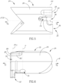
- the insert receiving pocket 46 has a maximum pocket height H at the pocket front opening 52a, as seen in an end view, measured in a direction perpendicular to the pocket longitudinal plane LP.
- the pocket lower clamping surface 54 can include two pocket lower clamping sub-surfaces 54a, 54b which are co-planar and spaced apart from each other along the pocket longitudinal axis L and in a direction away from the pocket front opening 52a, by a lower relief recess 56 recessed in the pocket lower surface 50.
- the insert holder 24 can include a lower support rib 58.
- the lower support rib 58 protrudes from the holder peripheral surface 26 and is located on the lower jaw 36 adjacent the pocket front opening 52a.
- the lower support rib 58 provides additional support to the cutting insert 22.
- the lower support rib 58 is narrower than the cutting insert 22 so as not to interfere during cutting operations.
- the pocket lower clamping surface 54 can extend onto the lower support rib 58 so as to extend further radially outward (relative to the holder axis B) than a corresponding surface on the upper the pocket upper surface 48 and thereby provide additional support against cutting forces.
- the pocket upper surface 48 includes a pocket upper clamping surface 60.
- the pocket upper clamping surface 60 is for firmly clamping a corresponding surface the cutting insert 22.
- the pocket upper clamping surface 60 faces mutually towards the pocket lower clamping surface 54 (i.e. the pocket upper clamping surface 60 and the pocket lower clamping surface 54 face towards each other).
- the pocket upper clamping surface 60 can be visible from a front opening view of the insert receiving pocket 46, i.e., along the pocket longitudinal axis L in front of the pocket front opening 52a (i.e. Fig. 4 ). Reverting to Fig.
- the pocket upper clamping surface 60 can slope towards the pocket longitudinal axis L (and also the pocket longitudinal plane LP) in a direction away from the pocket front opening 52a.
- the pocket upper clamping surface 60 can be planar.
- the pocket upper clamping surface 60 and the pocket lower clamping surface 54 can converge towards each other in a direction away from the pocket front opening 52a.
- the insert holder 24 can be devoid of a support rib protruding from the holder peripheral surface 26 at the upper jaw 36 adjacent the pocket front opening 52a.
- the insert receiving pocket 46 can include an insertion groove 62 recessed in the pocket upper clamping surface 60.
- the insertion groove 62 is used in the assembly of the cutting tool 20, and is described further on in the description.
- the insertion groove 62 can extend generally along the insertion direction D I, from the pocket front opening 52a.
- the insertion groove 62 can extend centrally along an entire longitudinal extent of the pocket upper clamping surface 60 so that the pocket upper clamping surface 60 includes two co-planar pocket upper clamping sub-surfaces 60a, 60b which are spaced apart from each other in a direction away from the holder end surface 28 by the insertion groove 62.
- the insert receiving pocket 46 can include at least one generally forward facing pocket axial abutment surface 64 formed on the lower jaw 36 which delimits the insert receiving pocket 46 in the rearward direction D R of the insert holder 24.
- the at least one pocket axial abutment surface 64 serves to prevent rearward displacement of the cutting insert 22 during metal cutting operations. In combination with the sloping pocket lower clamping surface 54, it can also provide a wedge-like lower seating for the cutting insert 22.
- the at least one pocket axial abutment surface 64 can be spaced apart from the pocket lower clamping surface 54.
- the lower jaw 36 can include two pocket axial abutment surfaces 64 which are spaced apart from each other in a direction away from the pocket lower clamping surface 54 by an axial relief recess 66.
- the two pocket axial abutment surfaces 64 may be located on opposite sides of the pocket longitudinal plane LP.
- the pocket axial abutment surface 64 that is closest to the pocket lower clamping surface 54 can extend longitudinally in a direction parallel to the pocket longitudinal axis L between the first and second recess side openings 40a, 40b.
- the pocket upper surface 48 includes a pocket stopper surface 68.
- the pocket stopper surface 68 is for positioning the cutting insert 22 in a predefined position when inserting the cutting insert 22 into the insert receiving pocket 46. It also serves to prevent inward displacement of the cutting insert 22 further into the insert receiving pocket 46 along the pocket longitudinal axis L during metal cutting operations.
- the pocket stopper surface 68 faces generally towards the pocket front opening 52a in order to serve as a stopper.
- the upper jaw 34 includes a stopper support portion 69 located behind the pocket stopper surface 68 (i.e. further from the pocket front opening 52a than the pocket stopper surface 68).
- the pocket stopper surface 68 is formed on the stopper support portion 69.
- the pocket stopper surface 68 is closer to the pocket lower clamping surface 54 than the pocket upper clamping surface 60.
- the pocket stopper surface 68 is further from pocket front opening 52a than the pocket upper clamping surface 60.
- the pocket lower clamping surface 54 extends along the pocket longitudinal axis L, closer to the pocket rear opening 52b than the pocket stopper surface 68.
- the stopper support portion 69 does not affect the radial dimension of the cutting tool. Typically, this allows internal cutting operations in holes having a diameter in the order of 5 mm.
- the pocket stopper surface 68 is visible in the front opening view of the insert receiving pocket 46.
- the pocket stopper surface 68 can slope towards the pocket longitudinal axis L (and also the pocket longitudinal plane LP) in a direction away from the pocket front opening 52a.
- the pocket stopper surface 68 can slope more steeply towards the pocket longitudinal plane LP in a direction away from the pocket front opening 52a than the pocket upper clamping surface 60.
- the pocket stopper surface 68 can be planar. Similar to the pocket upper clamping surface 60, the pocket stopper surface 68 and the pocket lower clamping surface 54 can converge towards each other in a direction away from the pocket front opening 52a.
- the insert holder 24 can include a resilience slot 70 formed in the clamping recess 38.
- the insert resilience slot 70 is primarily designed to provide the desired flexibility to the upper jaw 34.
- the upper jaw 34 should be flexible enough to allow insertion of the cutting insert 22 into the insert receiving pocket 46.
- the upper jaw 34 should be rigid enough to provide sufficient clamping of the cutting insert 22.
- the resilience slot 70 extends rearwardly from the insert receiving pocket 46.
- the resilience slot 70 merges with the insert receiving pocket 46.
- the resilience slot 70 has a maximum slot width W, as seen in a front end view of the insert holder 24 (i.e. Fig. 3 ), measured in a direction perpendicular to the recess upper and lower surfaces 42, 44 44 at the resilience slot 70.
- the maximum slot width W can be less than the maximum pocket height H.
- the resilience slot 70 is narrower than the insert receiving pocket 46.
- the resilience slot 70 can be entirely spaced apart from the holder end surface 28 by the insert receiving pocket 46. That is to say, the resilience slot 70 does not extend to the holder end surface 28 even though portions of the recess upper and/or lower surfaces 42, 44 may be smoothly continuous where the resilience slot 70 and the insert receiving pocket 46 merge with each other.
- the recess upper surface 42 may be smoothly continuous where the insert receiving pocket 46 intersects the resilience slot 70.
- the resilience slot 70 can include a first slot portion 72 and a second slot portion 74, the first slot portion 72 being adjacent the first recess side opening 40a and the second slot portion 74 being adjacent the second recess side opening 40b.
- the first and second slot portions 72, 74 can merge with each other.
- the first slot portion 72 can include a slot stress relief groove 76 where the resilience slot 70 terminates in the rearward direction D R .
- the slot stress relief groove 76 can extend along the pivot axis P.
- the second slot portion 74 can be devoid of a stress relief groove.
- the first and second slot portions 72, 74 can extend in different planes.
- the upper jaw 34 can include an inner flexibility groove 78 recessed in the recess upper surface 42.
- the inner flexibility groove 78 is designed to provide the desired flexibility to the upper jaw 34. It is also designed so that the pocket stopper surface 68 is not displaced (i.e. remains in the predefined position) during insertion of the cutting insert 22 into the insert receiving pocket 46.
- the inner flexibility groove 78 also provides a clearance gap for avoiding contact with any port of the cutting insert 22.
- the inner flexibility groove 78 can open out to the holder end surface 28 at an inner flexibility groove opening 80. Referring to Fig.
- the inner flexibility groove 78 can extend to beyond the insert receiving pocket 46 in the rearward direction D R of the insert holder 24.
- the inner flexibility groove 78 can be oriented parallel to the holder longitudinal axis B.
- the inner flexibility groove 78 can extend to the slot stress relief groove 76.
- the pocket upper clamping surface 60 and the pocket stopper surface 68 can be spaced apart from each other by the inner flexibility groove 78.
- the pocket stopper surface 68 may not be formed in the inner flexibility groove 78.
- the upper jaw 34 can include an outer flexibility groove 82 recessed in the holder peripheral surface 26. Similar to the inner flexibility groove 78, the outer flexibility groove 82 is designed to provide the desired flexibility and rigidity to the upper jaw 34.
- the outer flexibility groove 82 can open out to the holder end surface 28 at an outer flexibility groove opening 84.
- the outer flexibility groove 82 can extend to beyond the insert receiving pocket 46 in the rearward direction D R of the insert holder 24.
- the outer flexibility groove 82 can be oriented parallel to the holder longitudinal axis B. In a direction along the pocket longitudinal axis L, the outer flexibility groove opening 84 can be further from the pocket front opening 52a than the pocket stopper surface 68.
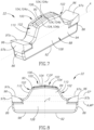
- the cutting insert 22 is integrally formed to have a unitary one-piece construction.
- the cutting insert 22 includes two opposing insert end surfaces 86 and an insert peripheral surface 88 extending between the two insert end surfaces 86.
- the insert peripheral surface 88 extends circumferentially about an insert longitudinal axis A.
- the insert longitudinal axis A defines a length direction of the insert, i.e., the direction in which the cutting insert 22 is longitudinally elongated and has is longest dimension.
- the insert peripheral surface 88 includes opposing insert upper and lower surfaces 90, 92 and two opposing insert side surfaces 94 all connecting the two insert end surfaces 86.
- the cutting insert 22 can be devoid of a through hole, for a retaining screw.
- the cutting insert 22 includes two cutting edges 96 formed at the intersection of the insert upper surface 90 and the two insert end surfaces 86, respectively. Stated differently, the cutting insert 22 is double-ended and is two-way indexable. A portion of the insert upper surface 90 adjacent each cutting edge 96 serves as a rake surface 97a. A portion of each insert end surface 86 adjacent a respective cutting edge 96 serves as a relief surface 97b.
- the insert longitudinal axis A intersects the insert end surfaces 86 and passes between the insert upper and lower surfaces 90, 92 and the insert side surfaces 94.
- An insert median plane MP located between the insert upper and lower surface 90, 92 contains the insert longitudinal axis A and intersects the two opposing insert side surfaces 94 and also the two opposing insert end surfaces 86.
- the insert longitudinal axis A and the insert median plane MP may be located midway between the insert upper and lower surfaces 90, 92.
- the cutting insert 22 has an insert central (vertical) axis F perpendicular to, and intersecting with, the insert longitudinal axis A, and intersecting the insert upper and lower surfaces 90, 92.
- the insert central axis F is located midway between the insert end surfaces 86 and extends along a height direction of the insert, thereby establishing an upward-to-downward direction of the insert.
- An insert longitudinal plane IP located between the insert side surfaces 94, contains both the insert longitudinal axis A and the insert central axis F, and intersects the insert upper and lower surface 90, 92 and also the two opposing insert end surfaces 86.
- the cutting insert 22 can exhibit mirror symmetry about the insert longitudinal plane IP.
- the cutting insert 22 has a cutting edge plane EP which is perpendicular to the insert central axis F and which is defined by the uppermost portions of the two cutting edges 96.
- the two cutting edges 96 may be contained in the cutting edge plane EP.
- the cutting insert 22 has an insert lateral axis G perpendicular to, and intersecting with, the insert longitudinal axis A and the insert central axis F.
- the insert lateral axis G extends in a width direction of the insert.
- the cutting insert 22 can exhibit 180° rotational symmetry about the insert central axis F.
- the insert longitudinal axis A and the insert lateral axis G may define the insert median plane MP.
- An insert transverse plane GP located between the insert end surfaces 86 contains both the insert lateral axis G and the insert central axis F, and intersects the insert upper and lower surfaces 90, 92 and also the two opposing insert side surfaces 94.
- the cutting insert 22 can exhibit mirror symmetry about the insert transverse plane GP.
- the insert lower surface 92 includes at least one insert lower abutment surface 98.
- the at least one insert lower abutment surface 98 can extend parallel to the insert longitudinal axis A.
- the insert lower surface 92 can include a single insert lower abutment surface 98 which is planar (not shown).
- the insert lower surface 92 can include two insert lower abutment surfaces 98 which are planar and slope towards the insert central axis F (and thus the insert longitudinal plane IP) in a direction away from the insert upper surface 90.
- the cutting insert 22 includes a mounting projection 100 projecting from the insert upper surface 90.
- the mounting projection 100 can extend between the two insert side surfaces 94, in the width direction of the insert.
- the mounting projection 100 can be spaced apart from the two rake surfaces 97a, in a direction along the insert longitudinal axis A.
- the mounting projection 100 includes two insert bearing surfaces 102.
- the two insert bearing surfaces 102 are formed on the insert upper surface 90 on the side of the cutting edge plane EP opposite the insert lower surface 92. Stated differently, the two insert bearing surfaces 102 are formed on the insert upper surface 90 above the cutting edge plane EP.
- the two insert bearing surfaces 102 are located on opposite sides of the insert transverse plane GP, and thus can be considered offset in the direction of the insert longitudinal axis A.
- Each cutting edge 96 is associated with the insert bearing surface 102 that is closest thereto.
- the two insert bearing surfaces 102 can be located on opposite axial sides of the mounting projection 100.
- Each insert bearing surface 102 includes an insert upper abutment surface 104.
- the insert upper abutment surface 104 is for abutting a corresponding surface in the insert receiving pocket 46.
- the two insert upper abutment surfaces 104 face mutually away from the at least one insert lower abutment surface 98 (stated differently, the insert upper abutment surface 104 and the at least one insert lower abutment surface 98 face away from each other).
- each insert upper abutment surface 104 can be planar. Each insert upper abutment surface 104 can be parallel to the insert lateral axis G. The two insert upper abutment surfaces 104 can be adjacent each other.
- the insert upper abutment surface 104 can slope towards the insert longitudinal axis A in a direction towards the associated cutting edge 96, i.e., its slopes towards the insert median plane MP.
- the insert upper abutment surface 104 can be visible from an end view of the cutting insert 22 along the insert longitudinal axis A in front of the associated cutting edge 96.
- the two insert upper abutment surface 104 can be smoothly continuous with each other and parallel to the insert longitudinal axis A so as to form a single continuous insert upper abutment surface 104 extending on both sides of the insert transverse plane GP (not shown). In such a configuration, the insert upper abutment surface 104 is not visible from an end view of the cutting insert 22.
- the mounting projection 100 includes two projecting insertion ridges 106.
- the insertion ridges 106 are designed to be positioned in the insertion groove 62 when inserting the cutting insert 22 in the insert receiving pocket 46, in the insertion direction Di towards the pocket rear opening 52b. By virtue of such, initial alignment of the cutting insert 22 with the insert receiving pocket 46 is made easier, and accidental falling of the cutting insert 22 from the insert receiving pocket 46, in the forward direction, is prevented.
- Each insertion ridge 106 can project from a respective insert upper abutment surface 104. Referring to Fig.
- each insertion ridge 106 extends centrally along an entire longitudinal extent of the insert upper abutment surface 104 so that each insert upper abutment surface 104 includes two parallel insert upper abutment sub-surfaces 104a, 104b which are co-planar and spaced apart from each other by the insertion ridge 106, on opposite sides of the insert longitudinal plane IP.
- each insert side surface 94 can include an insert side abutment surface 108.
- Each insert bearing surface 102 also includes an insert stopper surface 110.
- the insert stopper surface 110 is for abutting a corresponding surface in the insert receiving pocket 46.
- the insert stopper surface 110 is closer to the associated cutting edge 96 than the insert upper abutment surface 104.
- Each insert stopper surface 110 is visible from an end view of the cutting insert 22.
- the insert stopper surface 110 can slope towards the insert longitudinal axis A (and thus towards the insert median plane MP) in a direction towards the associated cutting edge 96. As shown in Fig.
- the insert stopper surface 110 can slope more steeply, towards the insert median plane MP in a direction towards the associated cutting edge 96, than the insert upper abutment surface 104.
- Each insert stopper surface 110 can be planar.
- Each insert stopper surface 110 can be parallel to the insert lateral axis G.
- the cutting tool 20 includes the cutting insert 22 releasably clamped in the insert receiving pocket 46 of the insert holder 24.
- the cutting insert 22 can be resiliently clamped in the insert receiving pocket 46.
- the cutting edge 96 that is outermost (and proximate the pocket front opening 52a) forms an active cutting edge 96a.
- the pocket stopper surface 68 can abut the insert stopper surface 110.
- the pocket lower clamping surface 54 can abut one of the at least one insert lower abutment surfaces 98.
- the pocket upper clamping surface 60 can abut the insert upper abutment surface 104 that is furthest from the active cutting edge 96a, i.e., the insert upper abutment surface 104 on the other side of the insert lateral plane GP.
- the at least one pocket axial abutment surface 64 can abut one of the insert side abutment surfaces 108. It is noted that one of the insertion ridges 106 can be located in the insertion groove 62. However, though located in the insertion groove 62, said one insertion ridge 106 can be spaced apart from the insertion groove 62, i.e., not actually contact the insertion groove 62.
- the pocket stopper surface 68 is located on the upper jaw 34 and does not abut a rearward portion of the cutting insert 22.
Landscapes
- Engineering & Computer Science (AREA)
- Mechanical Engineering (AREA)
- Cutting Tools, Boring Holders, And Turrets (AREA)
Claims (15)
- Länglicher Einsatzhalter (24) mit einer Halterlängsachse (B), die entgegengesetzte Richtungen nach vorn und nach hinten (DF, DR) definiert, wobei der Einsatzhalter (24) aufweist: eine Halterumfangsfläche (26), die sich in Umfangsrichtung um die Halterlängsachse (B) erstreckt, wobei die Halterumfangsfläche (26) eine Halterstirnfläche (28) an einem vorderen Ende des Einsatzhalters (24) schneidet und eine Begrenzung derselben bildet; einen Schaftabschnitt (30) und einen Einsatzbefestigungsabschnitt (32), der sich an einem vorderen Ende davon befindet, wobei der Einsatzbefestigungsabschnitt (32) aufweist:eine obere und untere Backe (34, 36), die durch eine Klemmausnehmung (38) voneinander beabstandet sind, wobei die Klemmausnehmung (38) in die Halterstirnfläche (28) eingelassen ist und sich zur Halterumfangsfläche (26) hin an einer ersten und zweiten Ausnehmungsseitenöffnung (40a, 40b) öffnet, wobei die obere Backe (34) in Bezug auf die untere Backe (36) durch Drehen um eine Drehachse (P) beweglich ist; undeine quer ausgerichtete Einsatzaufnahmetasche (46), die zum Aufnehmen eines Schneideinsatzes konfiguriert ist, wobei die Einsatzaufnahmetasche (46) in der Klemmausnehmung (38) ausgebildet ist und mindestens teilweise durch eine Taschenoberseite und Taschenunterseite (48, 50) definiert ist, die an der oberen bzw. unteren Backe (34, 36) ausgebildet sind und sich in Längsrichtung entlang einer Taschenlängsachse (L) zu der ersten und zweiten Ausnehmungsseitenöffnung (40a, 40b) erstrecken, um eine vordere bzw. hintere Taschenöffnung (52a, 52b) zu definieren; wobei:eine Taschenlängsebene (LP), die sich zwischen der Taschenoberseite und -unterseite (48, 50) befindet, die Taschenlängsachse (L) enthält;die Taschenunterseite (50) eine untere Taschenklemmfläche (54) aufweist;die Taschenoberseite (48) aufweist:eine obere Taschenklemmfläche (60), die der unteren Taschenklemmfläche (54) zugewandt ist; undeine Taschenanschlagfläche (68), die im Allgemeinen der vorderen Taschenöffnung (52a) zugewandt ist;die Taschenanschlagfläche (68) näher an der unteren Taschenklemmfläche (54) und weiter von der vorderen Taschenöffnung (52a) entfernt ist als die obere Taschenklemmfläche (60); undsich die untere Taschenklemmfläche (54) entlang der Taschenlängsachse erstreckt, dadurch gekennzeichnet, dass sich die untere Taschenklemmfläche (54) näher zu der hinteren Taschenöffnung (52b) als die Taschenanschlagfläche (68) erstreckt.
- Einsatzhalter (24) nach Anspruch 1, wobei die Taschenanschlagfläche (68) zur Taschenlängsebene (LP) hin von der vorderen Taschenöffnung (52a) weg geneigt ist; und bevorzugt:die obere Taschenklemmfläche (60) zur Taschenlängsebene (LP) hin von der vorderen Taschenöffnung (52a) weg geneigt ist; unddie Taschenanschlagfläche (68) steiler als die obere Taschenklemmfläche (60) geneigt ist.
- Einsatzhalter (24) nach einem der Ansprüche 1-2, wobei:die Einsatzaufnahmetasche (46) entlang einer Taschenquerebene (PP) ausgerichtet ist, die die Taschenlängsachse (L) enthält und die Taschenoberseite und -unterseite (48, 50) schneidet; unddie Taschenquerebene (PP) quer zur Halterlängsachse (B) verläuft; und bevorzugt:die Taschenquerebene (PP) senkrecht zur Halterlängsachse (B) verläuft; und ferner bevorzugtdie Taschenlängsebene (LP) senkrecht zur Taschenquerebene (PP) verläuft; und die untere Taschenklemmfläche (54) von der Taschenlängsebene (LP) in Rückwärtsrichtung (DR) abfällt.
- Einsatzhalter (24) nach einem der Ansprüche 1-3, wobei die Einsatzaufnahmetasche (46) eine Einführungsrille (62) aufweist, die in die obere Taschenklemmfläche (60) eingelassen ist und sich von der vorderen Taschenöffnung (52a) weg erstreckt; und bevorzugt:
die Einführungsrille (62) sich mittig entlang einer gesamten Längserstreckung der oberen Taschenklemmfläche (60) erstreckt, sodass die obere Taschenklemmfläche (60) zwei obere Taschenklemmteilflächen (60a, 60b) aufweist, die koplanar und voneinander in einer Richtung weg von der Halterstirnfläche (28) durch die Einführungsrille (62) beabstandet sind. - Einsatzhalter (24) nach einem der Ansprüche 1-4, wobei sich die Einsatzaufnahmetasche (46) bis zur zweiten Ausnehmungsseitenöffnung (40b) erstreckt, um eine hintere Taschenöffnung (52b) gegenüber der vorderen Taschenöffnung (52a) zu definieren.
- Einsatzhalter (24) nach einem der Ansprüche 1-5, wobei:die Klemmausnehmung (38) durch eine obere und eine gegenüberliegende untere Ausnehmungsfläche (42, 44) definiert ist, die an der oberen bzw. unteren Backe (34, 36) ausgebildet sind; unddie obere Backe (34) eine innere Flexibilitätsrille (78) aufweist, die in die obere Ausnehmungsfläche (42) eingelassen ist; und bevorzugt:
die innere Flexibilitätsrille (78) sich an einer inneren Flexibilitätsrillenöffnung (80) zur Halterstirnfläche (28) hin öffnet und sich in Rückwärtsrichtung (DR) des Einsatzhalters (24) über die Einsatzaufnahmetasche (46) hinaus erstreckt. - Einsatzhalter (24) nach einem der Ansprüche 1-6, wobei die Einsatzaufnahmetasche (46) mindestens eine an der unteren Backe (36) ausgebildete axiale Taschenanlagefläche (64) aufweist, die die Einsatzaufnahmetasche (46) in Rückwärtsrichtung (DR) des Einsatzhalters (24) begrenzt; und bevorzugt:
die untere Backe (36) zwei axiale Taschenanlageflächen (64) aufweist, die in einer von der unteren Taschenklemmfläche (54) wegführenden Richtung durch eine axiale Entlastungsausnehmung (66) voneinander beabstandet sind. - Einsatzhalter (24) nach einem der Ansprüche 1-7, wobei der Schaftabschnitt (30) und der Einsatzbefestigungsabschnitt (32) einstückig miteinander ausgebildet sind, um eine einheitliche einteilige Konstruktion zu erhalten.
- Schneidwerkzeug (20), aufweisend:einen Einsatzhalter (24) nach einem der Ansprüche 1-8; undeinen Schneideinsatz (22), der lösbar in die Einsatzaufnahmetasche (46) eingespannt ist.
- Schneidwerkzeug (20) nach Anspruch 9, wobei:
der Schneideinsatz (22) zwei Enden hat und in einer Richtung, die eine Einsatzlängsachse (A) definiert, elongiert ist und aufweist:zwei gegenüberliegende Einsatzstirnflächen (86) und eine sich dazwischen erstreckende Einsatzumfangsfläche (88), wobei sich die Einsatzumfangsfläche (88) in Umfangsrichtung um die Einsatzlängsachse (A) erstreckt und eine obere und gegenüberliegende untere Einsatzfläche (90, 92) und zwei gegenüberliegende Einsatzseitenflächen (94) aufweist, die alle die beiden Einsatzstirnflächen (86) verbinden; undzwei Schneidkanten (96), die am Schnittpunkt der oberen Einsatzfläche (90bzw. der beiden Einsatzstirnflächen (86) ausgebildet sind; undeinen Montagevorsprung (100), der von der oberen Einsatzfläche (90) hervorsteht, wobei der Montagevorsprung (100) zwei Einsatzauflageflächen (102) aufweist, die in Richtung der Einsatzlängsachse (A) versetzt sind und auf der oberen Einsatzfläche (90) oberhalb einer Schneidkantenebene (EP) ausgebildet sind, wobei jede Schneidkante (96) der ihr am nächsten liegenden Einsatzauflagefläche (102) zugeordnet ist; wobei:eine Einsatzmittelebene (MP), die sich zwischen der oberen und unteren Einsatzfläche (90, 92) befindet, die Einsatzlängsachse (A) enthält und die beiden gegenüberliegenden Einsatzseitenflächen (94) und auch die beiden gegenüberliegenden Einsatzstirnflächen (86) schneidet;eine Einsatzlängsebene (IP), die sich zwischen den gegenüberliegenden Einsatzseitenflächen (94) befindet, die Einsatzlängsachse (A) enthält und die obere und gegenüberliegende untere Einsatzfläche (90, 92) und auch die gegenüberliegenden Einsatzstirnflächen (86) schneidet;die untere Einsatzfläche (92) mindestens eine untere Einsatzanlagefläche (98) aufweist; undjede Einsatzauflagefläche (102) aufweist:eine obere Einsatzanlagefläche (104), die von der mindestens einen unteren Einsatzanlagefläche (98) abgewandt ist; undeine Einsatzanschlagfläche (110), die näher an der zugehörigen Schneidkante (96) und auch an der unteren Einsatzanlagefläche (98) liegt als die obere Einsatzanlagefläche (104); und bevorzugt:jede Einsatzanschlagfläche (110) zur Einsatzmittelebene (MP) in Richtung der zugehörigen Schneidkante (96) geneigt ist. - Schneidwerkzeug (20) nach Anspruch 10, wobei:jede obere Einsatzanlagefläche (104) zur Einsatzmittelebene (MP) in Richtung der zugehörigen Schneidkante (96) geneigt ist; unddie Einsatzanschlagfläche (110) für jede gegebene Einsatzauflagefläche (102) steiler abfällt als die obere Einsatzanlagefläche (104).
- Schneidwerkzeug (20) nach Anspruch 10 oder 11, wobei der Schneideinsatz (22) in der Einsatzaufnahmetasche (46) elastisch eingespannt ist.
- Schneidwerkzeug (20) nach einem der Ansprüche 10-12, wobei:die Schneidkante (96), die sich in der Nähe der vorderen Taschenöffnung (52a) befindet,eine aktive Schneidkante (96a) bildet;die Taschenanschlagfläche (68) an der Einsatzanschlagfläche (110) anliegt;die untere Taschenklemmfläche (54) an eine der mindestens einen unteren Einsatzanlagefläche (98) anliegt; unddie obere Taschenklemmfläche (60) an der oberen Einsatzanlagefläche (104) anliegt, die am weitesten von der aktiven Schneidkante (96a) entfernt ist; und bevorzugt:die Einsatzaufnahmetasche (46) mindestens eine nach vorne weisende axiale Taschenanschlagfläche (64) aufweist, die an der unteren Backe (36) ausgebildet ist, um die Einsatzaufnahmetasche (46) in Rückwärtsrichtung (DR) zu begrenzen;jede Einsatzseitenfläche (94) eine Einsatzseitenanlagefläche (108) aufweist; unddie mindestens eine axiale Taschenanlagefläche (64) an einer der Einsatzseitenflächen (94) anliegt.
- Schneidwerkzeug (20) nach einem der Ansprüche 10-13, wobei der Montagevorsprung (100) zwei vorstehende Einführungsstege (106) aufweist, wobei jeder Einführungssteg (106) von einer jeweiligen oberen Einsatzanlagefläche (104) hervorsteht.
- Schneideinsatz (22) mit zwei Enden, der in Längsrichtung in einer Richtung elongiert ist, die eine Einsatzlängsachse (A) definiert, aufweisend:zwei gegenüberliegende Einsatzstirnflächen (86) und eine sich dazwischen erstreckende Einsatzumfangsfläche (88), wobei sich die Einsatzumfangsfläche (88) in Umfangsrichtung um die Einsatzlängsachse (A) erstreckt und eine obere und gegenüberliegende untere Einsatzfläche (90, 92) und zwei gegenüberliegende Einsatzseitenflächen (94) aufweist, die alle die beiden Einsatzstirnflächen (86) verbinden; undzwei Schneidkanten (96), die am Schnittpunkt der oberen Einsatzfläche (90) bzw. der beiden Einsatzstirnflächen (86) ausgebildet sind; undeinen Montagevorsprung (100), der von der oberen Einsatzfläche (90) hervorsteht, wobei der Montagevorsprung (100) zwei Einsatzauflageflächen (102) aufweist, die in Richtung der Einsatzlängsachse (A) versetzt sind und auf der oberen Einsatzfläche (90) oberhalb einer Schneidkantenebene (EP) ausgebildet sind, wobei jede Schneidkante (96) der ihr am nächsten liegenden Einsatzauflagefläche (102) zugeordnet ist; wobei:eine Einsatzmittelebene (MP), die sich zwischen der oberen und unteren Einsatzfläche (90, 92) befindet, die Einsatzlängsachse (A) enthält und die beiden gegenüberliegenden Einsatzseitenflächen (94) und auch die beiden gegenüberliegenden Einsatzstirnflächen (86) schneidet;eine Einsatzlängsebene (IP), die sich zwischen den gegenüberliegenden Einsatzseitenflächen (94) befindet, die Einsatzlängsachse (A) enthält und die obere und gegenüberliegende untere Einsatzfläche (90, 92) und auch die gegenüberliegenden Einsatzstirnflächen (86) schneidet;die untere Einsatzfläche (92) mindestens eine untere Einsatzanlagefläche (98) aufweist; undjede Einsatzauflagefläche (102) aufweist:eine obere Einsatzanlagefläche (104), die von der mindestens einen unteren Einsatzanlagefläche (98) abgewandt ist; undeine Einsatzanschlagfläche (110), die näher an der zugehörigen Schneidkante (96) und der unteren Einsatzanlagefläche (98) liegt als die obere Einsatzanlagefläche (104);wobei:die obere Einsatzanlagefläche (104) und die Einsatzanschlagfläche (110) zur Einsatzmittelebene (MP) in Richtung der zugehörigen Schneidkante (96) geneigt sind, wobei die Einsatzanschlagfläche (110) steiler geneigt ist als die obere Einsatzanlagefläche (104);dadurch gekennzeichnet, dassder Montagevorsprung (100) zwei vorspringende Einführungsstege (106) aufweist, wobei jeder Einführungssteg (106) von einer jeweiligen oberen Einsatzanlagefläche (104) hervorsteht, und dadurch, dassjeder Einführungssteg (106) sich mittig entlang einer gesamten Längserstreckung der oberen Einsatzanlagefläche (104) erstreckt, so dass jede obere Einsatzanlagefläche (104) zwei parallele obere Einsatzanlageteilflächen (104a, 104b) aufweist, die koplanar und durch den Einführungssteg (106) auf gegenüberliegenden Seiten der Einsatzlängsebene (IP) voneinander beabstandet sind.
Applications Claiming Priority (2)
| Application Number | Priority Date | Filing Date | Title |
|---|---|---|---|
| US16/357,458 US10857603B2 (en) | 2019-03-19 | 2019-03-19 | Insert holder having transversely oriented insert receiving pocket with upper stopper surface, cutting tool and cutting insert |
| PCT/IL2020/050198 WO2020188554A1 (en) | 2019-03-19 | 2020-02-24 | Insert holder for a transversely oriented insert, cutting tool and cutting insert |
Publications (2)
| Publication Number | Publication Date |
|---|---|
| EP3941669A1 EP3941669A1 (de) | 2022-01-26 |
| EP3941669B1 true EP3941669B1 (de) | 2024-11-13 |
Family
ID=69941422
Family Applications (1)
| Application Number | Title | Priority Date | Filing Date |
|---|---|---|---|
| EP20713385.1A Active EP3941669B1 (de) | 2019-03-19 | 2020-02-24 | Einsatzhalter für einen quer ausgerichteten einsatz, schneidwerkzeug und schneideinsatz |
Country Status (13)
| Country | Link |
|---|---|
| US (2) | US10857603B2 (de) |
| EP (1) | EP3941669B1 (de) |
| JP (1) | JP7557471B2 (de) |
| KR (1) | KR102809671B1 (de) |
| CN (1) | CN113573832B (de) |
| BR (1) | BR112021016742A2 (de) |
| CA (1) | CA3133601A1 (de) |
| ES (1) | ES2993568T3 (de) |
| IL (1) | IL285406A (de) |
| PL (1) | PL3941669T3 (de) |
| PT (1) | PT3941669T (de) |
| TW (1) | TWI821505B (de) |
| WO (1) | WO2020188554A1 (de) |
Families Citing this family (3)
| Publication number | Priority date | Publication date | Assignee | Title |
|---|---|---|---|---|
| US12275078B2 (en) | 2022-05-03 | 2025-04-15 | Iscar, Ltd. | Rotationally asymmetric double-ended grooving cutting insert, insert holder and cutting tool |
| US11904393B1 (en) * | 2022-08-18 | 2024-02-20 | Iscar, Ltd. | External grooving insert holder having upper and lower jaws connected by angled hinge portion with cooling channel extending through hinge portion, and cutting tool |
| US12465981B2 (en) | 2022-09-07 | 2025-11-11 | Iscar, Ltd. | Cemented carbide cutting insert for parting metal workpieces |
Citations (5)
| Publication number | Priority date | Publication date | Assignee | Title |
|---|---|---|---|---|
| US3841785A (en) * | 1972-06-09 | 1974-10-15 | K Werther | Boring bar |
| US5833403A (en) * | 1995-10-06 | 1998-11-10 | Iscar Ltd. | Cutting tool assembly having an exchangeable adaptor |
| US20150003921A1 (en) * | 2013-06-28 | 2015-01-01 | Sandvik Intellectual Property Ab | Tool for chip removing machining as well as an insert-holding blade and a replaceable cutting insert therefor |
| US20170333997A1 (en) * | 2014-10-29 | 2017-11-23 | Kyocera Corporation | Holder, cutting tool, and method of producing machined product |
| WO2020152040A1 (de) * | 2019-01-21 | 2020-07-30 | Gühring KG | Maschinenwerkzeug |
Family Cites Families (31)
| Publication number | Priority date | Publication date | Assignee | Title |
|---|---|---|---|---|
| US3551977A (en) | 1969-04-08 | 1971-01-05 | Warner Swasey Co | Blade-like cutoff tool |
| JPS5950606U (ja) * | 1982-09-24 | 1984-04-03 | 木下 節男 | 内溝切りクランプバイト |
| DE3909358C2 (de) | 1989-03-22 | 1994-09-29 | Zinner Gmbh Praezisionswerkzeuge | Spanendes Werkzeug |
| GB8920227D0 (en) * | 1989-09-07 | 1989-10-18 | Iscar Hartmetall | A cutting insert |
| DE4024096A1 (de) | 1990-07-30 | 1992-02-06 | Hollfelder Hans Peter | Schneidwerkzeug, insbesondere bohrstange |
| US5159863A (en) | 1991-04-30 | 1992-11-03 | Manchester Tool Company | Adjustable face grooving tool holder |
| DE4415425A1 (de) | 1994-05-03 | 1995-11-09 | Krupp Widia Gmbh | Spanendes Werkzeug |
| EP0878260B1 (de) * | 1997-03-27 | 2001-12-19 | Sandvik Aktiebolag | Ein- und Abstechwerkzeug |
| JPH11104904A (ja) * | 1997-09-30 | 1999-04-20 | Toshiba Tungaloy Co Ltd | 溝入れ用バイトホルダおよびそのスローアウェイチップ |
| JP4782450B2 (ja) | 2005-03-23 | 2011-09-28 | 京セラ株式会社 | 内径加工用ホルダおよび切削工具 |
| JP4824767B2 (ja) | 2006-10-31 | 2011-11-30 | 京セラ株式会社 | 切削インサート |
| EP1980348B1 (de) | 2007-03-30 | 2012-03-07 | Mitsubishi Materials Corporation | Schneideeinsatz |
| EP1980349A3 (de) | 2007-03-30 | 2009-02-11 | Mitsubishi Materials Corporation | Schneideeinsatz |
| EP2140959B1 (de) | 2007-04-20 | 2016-09-28 | Mitsubishi Materials Corporation | Schneideinsatz und schneidverfahren |
| AT505360B1 (de) * | 2007-05-24 | 2011-09-15 | Boehlerit Gmbh & Co Kg | Schneidwerkzeug mit lösbar befestigten schneidplatten |
| DE202009014789U1 (de) | 2009-11-02 | 2010-02-18 | Holler, Dirk | Drehend antreibbares Schneidwerkzeug |
| IL203014A (en) * | 2009-12-29 | 2013-03-24 | Iscar Ltd | Cutting tool and cutting insert therefor |
| KR101075292B1 (ko) | 2010-01-14 | 2011-10-20 | 대구텍 유한회사 | 절삭 공구 |
| IL205091A (en) | 2010-04-14 | 2014-01-30 | Iscar Ltd | Cutting tools and cutting tool for him |
| KR101699595B1 (ko) * | 2011-08-02 | 2017-01-24 | 이스카 엘티디. | 절삭 공구 및 절삭 공구에 절삭 인서트를 고정하기 위한 클램핑 기구 |
| US9033622B2 (en) | 2012-01-03 | 2015-05-19 | Iscar, Ltd. | Cutting insert having curved ramps for insertion into a tool holder, cutting tool and method of assembly |
| US8647029B2 (en) | 2012-01-03 | 2014-02-11 | Iscar, Ltd. | Cutting tool and method for extracting cutting insert therefrom |
| US8696259B2 (en) | 2012-02-02 | 2014-04-15 | Iscar, Ltd. | Tool holder having set screw for clamping a cutting insert therein |
| US20130294854A1 (en) | 2012-05-02 | 2013-11-07 | Taegutec, Ltd. | Cutting tool assembly |
| CN104428086B (zh) | 2012-09-27 | 2017-06-30 | 京瓷株式会社 | 切削镶刀以及切削工具 |
| US8985913B2 (en) * | 2012-11-13 | 2015-03-24 | Iscar, Ltd. | Cutting tool holder with internal coolant passage having a compressible member |
| US9120239B2 (en) | 2013-02-21 | 2015-09-01 | Iscar, Ltd. | Cutting tool and cutting insert having insert key recesses for extracting and mounting therein |
| US9656326B2 (en) | 2013-04-24 | 2017-05-23 | Iscar, Ltd. | Tool holder having a clamping member with a non-circular cross-section and method for clamping a cutting insert therein |
| US9999927B2 (en) * | 2015-11-30 | 2018-06-19 | Iscar, Ltd. | Parting-off tool assembly with single-cutting-edged solid cutting insert and rigid-insert-seat tool |
| US10166607B2 (en) * | 2016-10-05 | 2019-01-01 | Iscar, Ltd. | Tetrahedron-shaped cutting insert, insert holder and cutting tool |
| US10363722B2 (en) * | 2017-03-23 | 2019-07-30 | Iscar, Ltd. | Blade-shaped cutting insert and cutting tool therefor |
-
2019
- 2019-03-19 US US16/357,458 patent/US10857603B2/en active Active
-
2020
- 2020-01-17 TW TW109101671A patent/TWI821505B/zh active
- 2020-02-24 JP JP2021544274A patent/JP7557471B2/ja active Active
- 2020-02-24 BR BR112021016742-0A patent/BR112021016742A2/pt unknown
- 2020-02-24 ES ES20713385T patent/ES2993568T3/es active Active
- 2020-02-24 WO PCT/IL2020/050198 patent/WO2020188554A1/en not_active Ceased
- 2020-02-24 PT PT207133851T patent/PT3941669T/pt unknown
- 2020-02-24 KR KR1020217030591A patent/KR102809671B1/ko active Active
- 2020-02-24 PL PL20713385.1T patent/PL3941669T3/pl unknown
- 2020-02-24 CA CA3133601A patent/CA3133601A1/en active Pending
- 2020-02-24 EP EP20713385.1A patent/EP3941669B1/de active Active
- 2020-02-24 CN CN202080021673.9A patent/CN113573832B/zh active Active
- 2020-10-14 US US17/069,974 patent/US11471953B2/en active Active
-
2021
- 2021-08-05 IL IL285406A patent/IL285406A/en unknown
Patent Citations (5)
| Publication number | Priority date | Publication date | Assignee | Title |
|---|---|---|---|---|
| US3841785A (en) * | 1972-06-09 | 1974-10-15 | K Werther | Boring bar |
| US5833403A (en) * | 1995-10-06 | 1998-11-10 | Iscar Ltd. | Cutting tool assembly having an exchangeable adaptor |
| US20150003921A1 (en) * | 2013-06-28 | 2015-01-01 | Sandvik Intellectual Property Ab | Tool for chip removing machining as well as an insert-holding blade and a replaceable cutting insert therefor |
| US20170333997A1 (en) * | 2014-10-29 | 2017-11-23 | Kyocera Corporation | Holder, cutting tool, and method of producing machined product |
| WO2020152040A1 (de) * | 2019-01-21 | 2020-07-30 | Gühring KG | Maschinenwerkzeug |
Also Published As
| Publication number | Publication date |
|---|---|
| IL285406A (en) | 2021-09-30 |
| JP7557471B2 (ja) | 2024-09-27 |
| PT3941669T (pt) | 2024-11-25 |
| CA3133601A1 (en) | 2020-09-24 |
| TWI821505B (zh) | 2023-11-11 |
| CN113573832A (zh) | 2021-10-29 |
| KR102809671B1 (ko) | 2025-05-20 |
| KR20210137063A (ko) | 2021-11-17 |
| TW202039121A (zh) | 2020-11-01 |
| US10857603B2 (en) | 2020-12-08 |
| US20210023633A1 (en) | 2021-01-28 |
| WO2020188554A1 (en) | 2020-09-24 |
| BR112021016742A2 (pt) | 2021-10-19 |
| EP3941669A1 (de) | 2022-01-26 |
| ES2993568T3 (en) | 2025-01-02 |
| US11471953B2 (en) | 2022-10-18 |
| CN113573832B (zh) | 2024-11-08 |
| US20200298325A1 (en) | 2020-09-24 |
| JP2022524573A (ja) | 2022-05-09 |
| PL3941669T3 (pl) | 2025-01-27 |
Similar Documents
| Publication | Publication Date | Title |
|---|---|---|
| US10953474B2 (en) | Insert holder having transversely oriented insert receiving pocket with resilient upper jaw having outer flexibility groove and cutting tool | |
| EP2416911B1 (de) | Schneidwerkzeuganordnung und werkzeughalter dafür | |
| EP3941669B1 (de) | Einsatzhalter für einen quer ausgerichteten einsatz, schneidwerkzeug und schneideinsatz | |
| CN101652216A (zh) | 切削工具和用于将切削部件附接于刀具本体的系统 | |
| US20190160555A1 (en) | Slotting tool body having inwardly offset insert receiving slot, rotary slot cutting tool having same and cutting insert | |
| US7264424B2 (en) | Tool head for a machining tool | |
| EP3600733B1 (de) | Schneideinsatz mit zwei peripheren stützrippen und schneidwerkzeug | |
| SE525462C2 (sv) | Verktygshuvud för spånavskiljande metallbearbetningsverktyg med spännskruv vilken ingängas i en mutterrulle | |
| EP3523072B1 (de) | Tetraederförmiger schneideinsatz, einsatzhalter und schneidwerkzeug | |
| US11904393B1 (en) | External grooving insert holder having upper and lower jaws connected by angled hinge portion with cooling channel extending through hinge portion, and cutting tool | |
| RU2804225C2 (ru) | Держатель режущей пластины для поперечно ориентированной режущей пластины, режущий инструмент и режущая пластина |
Legal Events
| Date | Code | Title | Description |
|---|---|---|---|
| STAA | Information on the status of an ep patent application or granted ep patent |
Free format text: STATUS: UNKNOWN |
|
| STAA | Information on the status of an ep patent application or granted ep patent |
Free format text: STATUS: THE INTERNATIONAL PUBLICATION HAS BEEN MADE |
|
| PUAI | Public reference made under article 153(3) epc to a published international application that has entered the european phase |
Free format text: ORIGINAL CODE: 0009012 |
|
| STAA | Information on the status of an ep patent application or granted ep patent |
Free format text: STATUS: REQUEST FOR EXAMINATION WAS MADE |
|
| 17P | Request for examination filed |
Effective date: 20210827 |
|
| AK | Designated contracting states |
Kind code of ref document: A1 Designated state(s): AL AT BE BG CH CY CZ DE DK EE ES FI FR GB GR HR HU IE IS IT LI LT LU LV MC MK MT NL NO PL PT RO RS SE SI SK SM TR |
|
| DAV | Request for validation of the european patent (deleted) | ||
| DAX | Request for extension of the european patent (deleted) | ||
| GRAP | Despatch of communication of intention to grant a patent |
Free format text: ORIGINAL CODE: EPIDOSNIGR1 |
|
| STAA | Information on the status of an ep patent application or granted ep patent |
Free format text: STATUS: GRANT OF PATENT IS INTENDED |
|
| INTG | Intention to grant announced |
Effective date: 20240715 |
|
| GRAS | Grant fee paid |
Free format text: ORIGINAL CODE: EPIDOSNIGR3 |
|
| GRAA | (expected) grant |
Free format text: ORIGINAL CODE: 0009210 |
|
| STAA | Information on the status of an ep patent application or granted ep patent |
Free format text: STATUS: THE PATENT HAS BEEN GRANTED |
|
| AK | Designated contracting states |
Kind code of ref document: B1 Designated state(s): AL AT BE BG CH CY CZ DE DK EE ES FI FR GB GR HR HU IE IS IT LI LT LU LV MC MK MT NL NO PL PT RO RS SE SI SK SM TR |
|
| P01 | Opt-out of the competence of the unified patent court (upc) registered |
Free format text: CASE NUMBER: APP_55199/2024 Effective date: 20241008 |
|
| REG | Reference to a national code |
Ref country code: GB Ref legal event code: FG4D |
|
| REG | Reference to a national code |
Ref country code: CH Ref legal event code: EP |
|
| REG | Reference to a national code |
Ref country code: PT Ref legal event code: SC4A Ref document number: 3941669 Country of ref document: PT Date of ref document: 20241125 Kind code of ref document: T Free format text: AVAILABILITY OF NATIONAL TRANSLATION Effective date: 20241118 |
|
| REG | Reference to a national code |
Ref country code: DE Ref legal event code: R096 Ref document number: 602020041253 Country of ref document: DE |
|
| REG | Reference to a national code |
Ref country code: IE Ref legal event code: FG4D |
|
| REG | Reference to a national code |
Ref country code: SE Ref legal event code: TRGR |
|
| REG | Reference to a national code |
Ref country code: ES Ref legal event code: FG2A Ref document number: 2993568 Country of ref document: ES Kind code of ref document: T3 Effective date: 20250102 |
|
| PGFP | Annual fee paid to national office [announced via postgrant information from national office to epo] |
Ref country code: PT Payment date: 20241217 Year of fee payment: 6 |
|
| PGFP | Annual fee paid to national office [announced via postgrant information from national office to epo] |
Ref country code: CZ Payment date: 20241220 Year of fee payment: 6 |
|
| REG | Reference to a national code |
Ref country code: LT Ref legal event code: MG9D |
|
| REG | Reference to a national code |
Ref country code: NL Ref legal event code: MP Effective date: 20241113 |
|
| PG25 | Lapsed in a contracting state [announced via postgrant information from national office to epo] |
Ref country code: HR Free format text: LAPSE BECAUSE OF FAILURE TO SUBMIT A TRANSLATION OF THE DESCRIPTION OR TO PAY THE FEE WITHIN THE PRESCRIBED TIME-LIMIT Effective date: 20241113 Ref country code: IS Free format text: LAPSE BECAUSE OF FAILURE TO SUBMIT A TRANSLATION OF THE DESCRIPTION OR TO PAY THE FEE WITHIN THE PRESCRIBED TIME-LIMIT Effective date: 20250313 |
|
| PGFP | Annual fee paid to national office [announced via postgrant information from national office to epo] |
Ref country code: DE Payment date: 20250107 Year of fee payment: 6 |
|
| PG25 | Lapsed in a contracting state [announced via postgrant information from national office to epo] |
Ref country code: FI Free format text: LAPSE BECAUSE OF FAILURE TO SUBMIT A TRANSLATION OF THE DESCRIPTION OR TO PAY THE FEE WITHIN THE PRESCRIBED TIME-LIMIT Effective date: 20241113 Ref country code: NL Free format text: LAPSE BECAUSE OF FAILURE TO SUBMIT A TRANSLATION OF THE DESCRIPTION OR TO PAY THE FEE WITHIN THE PRESCRIBED TIME-LIMIT Effective date: 20241113 |
|
| PG25 | Lapsed in a contracting state [announced via postgrant information from national office to epo] |
Ref country code: BG Free format text: LAPSE BECAUSE OF FAILURE TO SUBMIT A TRANSLATION OF THE DESCRIPTION OR TO PAY THE FEE WITHIN THE PRESCRIBED TIME-LIMIT Effective date: 20241113 |
|
| PGFP | Annual fee paid to national office [announced via postgrant information from national office to epo] |
Ref country code: ES Payment date: 20250303 Year of fee payment: 6 |
|
| PGFP | Annual fee paid to national office [announced via postgrant information from national office to epo] |
Ref country code: SE Payment date: 20250109 Year of fee payment: 6 |
|
| PG25 | Lapsed in a contracting state [announced via postgrant information from national office to epo] |
Ref country code: NO Free format text: LAPSE BECAUSE OF FAILURE TO SUBMIT A TRANSLATION OF THE DESCRIPTION OR TO PAY THE FEE WITHIN THE PRESCRIBED TIME-LIMIT Effective date: 20250213 |
|
| PG25 | Lapsed in a contracting state [announced via postgrant information from national office to epo] |
Ref country code: LV Free format text: LAPSE BECAUSE OF FAILURE TO SUBMIT A TRANSLATION OF THE DESCRIPTION OR TO PAY THE FEE WITHIN THE PRESCRIBED TIME-LIMIT Effective date: 20241113 Ref country code: GR Free format text: LAPSE BECAUSE OF FAILURE TO SUBMIT A TRANSLATION OF THE DESCRIPTION OR TO PAY THE FEE WITHIN THE PRESCRIBED TIME-LIMIT Effective date: 20250214 |
|
| PGFP | Annual fee paid to national office [announced via postgrant information from national office to epo] |
Ref country code: AT Payment date: 20250107 Year of fee payment: 6 Ref country code: CH Payment date: 20250301 Year of fee payment: 6 |
|
| PGFP | Annual fee paid to national office [announced via postgrant information from national office to epo] |
Ref country code: PL Payment date: 20241219 Year of fee payment: 6 Ref country code: FR Payment date: 20250108 Year of fee payment: 6 |
|
| PGFP | Annual fee paid to national office [announced via postgrant information from national office to epo] |
Ref country code: IT Payment date: 20250103 Year of fee payment: 6 Ref country code: GB Payment date: 20250109 Year of fee payment: 6 |
|
| PG25 | Lapsed in a contracting state [announced via postgrant information from national office to epo] |
Ref country code: RS Free format text: LAPSE BECAUSE OF FAILURE TO SUBMIT A TRANSLATION OF THE DESCRIPTION OR TO PAY THE FEE WITHIN THE PRESCRIBED TIME-LIMIT Effective date: 20250213 |
|
| PGFP | Annual fee paid to national office [announced via postgrant information from national office to epo] |
Ref country code: TR Payment date: 20250117 Year of fee payment: 6 |
|
| PG25 | Lapsed in a contracting state [announced via postgrant information from national office to epo] |
Ref country code: SM Free format text: LAPSE BECAUSE OF FAILURE TO SUBMIT A TRANSLATION OF THE DESCRIPTION OR TO PAY THE FEE WITHIN THE PRESCRIBED TIME-LIMIT Effective date: 20241113 |
|
| PG25 | Lapsed in a contracting state [announced via postgrant information from national office to epo] |
Ref country code: DK Free format text: LAPSE BECAUSE OF FAILURE TO SUBMIT A TRANSLATION OF THE DESCRIPTION OR TO PAY THE FEE WITHIN THE PRESCRIBED TIME-LIMIT Effective date: 20241113 |
|
| PG25 | Lapsed in a contracting state [announced via postgrant information from national office to epo] |
Ref country code: EE Free format text: LAPSE BECAUSE OF FAILURE TO SUBMIT A TRANSLATION OF THE DESCRIPTION OR TO PAY THE FEE WITHIN THE PRESCRIBED TIME-LIMIT Effective date: 20241113 |
|
| PG25 | Lapsed in a contracting state [announced via postgrant information from national office to epo] |
Ref country code: RO Free format text: LAPSE BECAUSE OF FAILURE TO SUBMIT A TRANSLATION OF THE DESCRIPTION OR TO PAY THE FEE WITHIN THE PRESCRIBED TIME-LIMIT Effective date: 20241113 |
|
| PG25 | Lapsed in a contracting state [announced via postgrant information from national office to epo] |
Ref country code: SK Free format text: LAPSE BECAUSE OF FAILURE TO SUBMIT A TRANSLATION OF THE DESCRIPTION OR TO PAY THE FEE WITHIN THE PRESCRIBED TIME-LIMIT Effective date: 20241113 |
|
| REG | Reference to a national code |
Ref country code: DE Ref legal event code: R097 Ref document number: 602020041253 Country of ref document: DE |
|
| PG25 | Lapsed in a contracting state [announced via postgrant information from national office to epo] |
Ref country code: MC Free format text: LAPSE BECAUSE OF FAILURE TO SUBMIT A TRANSLATION OF THE DESCRIPTION OR TO PAY THE FEE WITHIN THE PRESCRIBED TIME-LIMIT Effective date: 20241113 |
|
| PLBE | No opposition filed within time limit |
Free format text: ORIGINAL CODE: 0009261 |
|
| STAA | Information on the status of an ep patent application or granted ep patent |
Free format text: STATUS: NO OPPOSITION FILED WITHIN TIME LIMIT |
|
| PG25 | Lapsed in a contracting state [announced via postgrant information from national office to epo] |
Ref country code: LU Free format text: LAPSE BECAUSE OF NON-PAYMENT OF DUE FEES Effective date: 20250224 |
|
| 26N | No opposition filed |
Effective date: 20250814 |
|
| REG | Reference to a national code |
Ref country code: BE Ref legal event code: MM Effective date: 20250228 |
|
| PG25 | Lapsed in a contracting state [announced via postgrant information from national office to epo] |
Ref country code: BE Free format text: LAPSE BECAUSE OF NON-PAYMENT OF DUE FEES Effective date: 20250228 |
|
| PG25 | Lapsed in a contracting state [announced via postgrant information from national office to epo] |
Ref country code: IE Free format text: LAPSE BECAUSE OF NON-PAYMENT OF DUE FEES Effective date: 20250224 |