EP1513434B1 - Kaffeemaschine für espresso mit abnehmbaren wassertank - Google Patents
Kaffeemaschine für espresso mit abnehmbaren wassertank Download PDFInfo
- Publication number
- EP1513434B1 EP1513434B1 EP03760718A EP03760718A EP1513434B1 EP 1513434 B1 EP1513434 B1 EP 1513434B1 EP 03760718 A EP03760718 A EP 03760718A EP 03760718 A EP03760718 A EP 03760718A EP 1513434 B1 EP1513434 B1 EP 1513434B1
- Authority
- EP
- European Patent Office
- Prior art keywords
- water
- tank
- jet
- coffeemaker
- bore
- Prior art date
- Legal status (The legal status is an assumption and is not a legal conclusion. Google has not performed a legal analysis and makes no representation as to the accuracy of the status listed.)
- Expired - Lifetime
Links
Images


Classifications
-
- A—HUMAN NECESSITIES
- A47—FURNITURE; DOMESTIC ARTICLES OR APPLIANCES; COFFEE MILLS; SPICE MILLS; SUCTION CLEANERS IN GENERAL
- A47J—KITCHEN EQUIPMENT; COFFEE MILLS; SPICE MILLS; APPARATUS FOR MAKING BEVERAGES
- A47J31/00—Apparatus for making beverages
- A47J31/24—Coffee-making apparatus in which hot water is passed through the filter under pressure, i.e. in which the coffee grounds are extracted under pressure
- A47J31/34—Coffee-making apparatus in which hot water is passed through the filter under pressure, i.e. in which the coffee grounds are extracted under pressure with hot water under liquid pressure
- A47J31/36—Coffee-making apparatus in which hot water is passed through the filter under pressure, i.e. in which the coffee grounds are extracted under pressure with hot water under liquid pressure with mechanical pressure-producing means
Definitions
- the present invention relates to espresso-type electric coffee makers comprising a cold water tank, an electric pump, a boiler assembly and a filter container for receiving the ground coffee which will be infused with hot pressurized water from Boiler.
- thermoblock generally consists of an electric heating element in thermal relation with a water circuit, the water being circulated during operation of the pump.
- thermoblock At the end of the coffee beverage production cycle, it is necessary to realize a pressure relief in the hydraulic circuit of the machine, this relaxation is done for the vast majority of coffee machines by redirecting the flow of water under pressure to the cold water tank which thus receives the return flow.
- Such a coffee machine is known from the document FR 2 316 901 where a pump is mounted in the base of the machine and a cold water tank in the vertical column connecting the base to the upper part of the machine.
- the tank is removably mounted by being positioned in a frame belonging to the base of the machine.
- the mount receiving the removable reservoir has a cylindrical bore in the upper portion for communicating with the outlet of the tank and a bottom communicating with two downwardly connected pipes connected to the suction pipe of the pump and the another to a return duct in the tank.
- the object of the present invention is to overcome the aforementioned drawbacks and to provide an espresso coffee machine with removable tank operating efficiently while providing increased protection for the user when using the machine.
- Another object of the invention is an espresso machine of easy maintenance type, avoiding any problem of overflow or uncontrolled water flow when the removable tank is handled by the user.
- a further object of the invention is an espresso type coffee machine of simple and inexpensive construction, while being reliable in operation.
- an espresso type coffee machine with a removable tank connected to a main hydraulic circuit with a pump that draws water from the tank and sends it into a thermoblock and from here through the coffee grind contained in a filter holder, said reservoir being also connected to a hydraulic circuit allowing the return of the water leaving the thermoblock, the fact that the connection device of said tank with said hydraulic circuits comprises means for expanding the water jet arriving by the hydraulic return circuit to the tank and means for orienting said jet towards a storage area.
- this connection device first ensures a tight communication between the cold water tank of the machine and the rest of the hydraulic circuit.
- This tight connection can be achieved by an O-ring belonging to said connection device or to the reservoir, a seal situated between two re-entrant tubings of the two parts in communication.
- the tubing of the reservoir generally includes a valve that automatically closes the access to the tank when it is removed from its seat and opens the passage to the hydraulic circuit of the machine when the tank is put back in place.
- connection device also has the role of communicating the cold water tank with the main hydraulic circuit, which connects it to the suction pipe of the pump, as well as to the return circuit to the tank by a pipe of relaxation.
- the connection device comprises first means of expansion of the water jet returning to the reservoir.
- the pressure must be lowered in the hydraulic circuit leaving the thermoblock and for this reason, the flow of hot water is returned by the expansion pipe. to the tank. If the tank is in communication with the expansion pipe, this flow returns to the tank.
- the strong return flow is in any case broken by the said first means, which has the effect of obtaining a quiet jet and thus protecting the user against splashing. hot water under pressure.
- connection device of the invention further comprises second means for directing the flow of water back to a storage area.
- the quiet jet obtained with the first means is then directed towards a zone to collect this return flow, especially in the case where the tank is absent or if it is incorrectly positioned or, if for some reason, the seal between the latter and the connection device is broken. This prevents overflows on the outside of the machine or prevents the accumulation of stagnant water inside the machine in areas inaccessible for cleaning.
- the expansion means direct the water jet in a direction other than that of the main axis of the connection device of said tank with the hydraulic circuits of the machine.
- main axis of the tank connection device includes in particular the axis of the tubing of the tank where is arranged the valve, or the axis of the valve.
- This axis is, for most applications, vertical or normal to the work plane, but it can also be arranged in another direction. Directing the return water jet in a direction different from that of the main axis of the tank connection device, causes the powerful jet to undergo a pressure drop and at the same time it is deflected from the direction normal to the work plane or the seating plane of the connection device, so that it protects the user when the return jet is in the absence of the tank.
- connection device comprises a central bore placing it in communication on one side with said reservoir, on the other side the bore opening into two orifices communicating one with the main hydraulic circuit and the other with the hydraulic return circuit, wherein said means of expansion of the water jet are arranged in the extension of the axis of the orifice which communicates with the hydraulic return circuit.
- the turbulent jet that arrives through the return circuit in the orifice provided for this purpose in the connection device is calmed by expansion means which are arranged in the axis of this orifice thus having a direct effect on the jet powerful under pressure.
- This jet of return undergoes a loss of charge coming into contact with the means of relaxation, which makes it less dangerous for the user.
- said detent means comprise a plurality of parallel fins arranged alternately on a common axis.
- These fins constitute a buffer device for the powerful jet back and, by their arrangement on an axis opening into the inlet port of the jet of return water, force this jet of water to follow a sinuous course having effect a significant pressure drop and obtaining a jet of water sufficiently calm to be oriented or recovered later.
- said common axis comprises a deflector located in the axis of the closure valve of the reservoir when the latter is connected to the connection device.
- said water jet orientation means are arranged downstream of said water jet expansion means in the direction of flow of the water jet.
- said means for orienting the water jet comprise at least one passage placing in communication the inside of the bore of the device of connection with a funnel surrounding said bore.
- the jet of water expanded inside the central bore of the connection device is oriented towards a space close to this bore and concentric with the latter, a passage being provided for establishing a communication between said spaces containing the fluid that is back to the tank.
- said means for directing the water jet of the coffee machine of the invention comprise a first passage situated downstream of an O-ring sealing the reservoir and the bore of the connecting device such as as seen in the direction of flow of the water jet back to the tank.
- the return jet is returned to the inside of the reservoir.
- the seal no longer fulfills its role, so that the return water jet is directed by a passage located next to and downstream of the gasket. sealing in a storage area constituted by the funnel surrounding said bore.
- This first passage can be arranged at the upper edge of said bore or by making an opening located closer to the location of the seal in order to prevent the return jet from making long journeys before reaching the zone of storage.
- said first passage is made between the upper portion of the bore and the inner face of a plate affixed to the funnel.
- a plate is provided in the upper part of the funnel, at least one opening being provided between the two so that the return water jet follows this opening to reach the interior of the funnel.
- the water jet is thus easily channeled to the funnel closed by said plate, which prevents overflow or splashing inside the latter, for example following projections on the internal walls of the funnel, etc..
- said water jet orientation means comprise a second passage in the form of an opening made in the plate, opening located downstream of the first passage as seen in the direction of flow of the return water jet. to the tank.
- said means for orienting the water jet comprise channeling ribs located on either side of an orifice of the plate communicating with the bore of the connecting device, ribs arriving close to said opening.
- said possible overflows passing through the bore of the connection device arrive on the upper face of the plate provided with channeling ribs which collect these overflows and channel them to said opening opening into the funnel that captures these overflows.
- said means of orientation of the water jet communicate through a funnel outlet with a recovery tray removably mounted in the machine.
- the overflows stored temporarily in the funnel are returned to a recovery tank of larger dimensions than the funnel and which, in addition, is mounted removably relative to the body of the machine allowing the user to the empty easily.
- Said recovery tank comprises a gutter extension forming a recuperator coming under a recovery nozzle which is connected to a discharge pipe of the funnel.
- said recovery tank holds the brewing container holder.
- the infusion collection container holder is in the form of a grid held on its periphery by the rim of the recovery tank. This allows to collect in the same tray any drops resulting from the infusion of coffee. This keeps the machine environment clean and easy to clean.
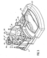
- FIG. 1 illustrates a coffee machine according to the invention comprising a body 1 whose lower part comprises a base 2 which is connected to the upper part of the body 1 by a vertical upright 3 serving to support a water tank 4 cold.
- the body 1 encloses the hydraulic circuit of the machine comprising the reservoir 4, a pump 5, a thermoblock 6, a distributor 7 and a cylinder 8 for compressing the coffee grounds.
- the ground coffee is placed in a cup provided with a filtering wall called filter holder 9 which is, in the example described, slidably mounted in a horizontal direction in the grooves of a fixed support of the infusion head 10 .
- the jack 8 comprises a nose mounted vertically sliding relative to the body 1 of the machine adapted to penetrate, during each operating cycle, inside the filter holder 9 to compress the grind.
- the water supplied by the pump 5 actuates the hydraulic cylinder 8 which pushes the nose against grinding.
- a valve located inside said nose allows the passage of water from the thermoblock 6 to the filter holder 9 from which the infusion flows into a collection container located on a support 11 of the base 2.
- the coffee machine comprises a boiler or thermoblock 6 for heating the pressurized water supplied by the pump 5 before injecting it into the coffee grounds of the filter holder 9.
- the thermoblock 6 comprises heat-exchange channels 17 enabling the flow of water inside the thermoblock 6 which furthermore comprises an electric heating element 12 and a temperature sensor 13.
- the water coming from the pump 5 arrives via an inlet channel 14 of the thermoblock 6 and can emerge along two paths of the latter, depending on the position of the distributor 7. Either the water leaves cold by an outlet channel 15, which forms with the inlet channel 14 a very short circuit that does not allow the water to to heat up in the thermoblock, the water comes out hot by an outlet channel 16 after having circulated in the heat exchange channels 17 of the thermoblock 6.
- the distributor 7 At the end of extraction of the coffee drink, the distributor 7 is returned to the rest position by the user, so that the pressurized hot water of the hydraulic circuit is sent through an expansion pipe to the tank 4.
- the tank 4 is removably mounted on the machine of the invention and it comprises, as shown in Figure 2, hooks 20 which can engage in eyelets 21 provided for this purpose in the front wall screw vertical tank 3.
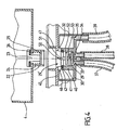
- the tank 4 has a generally parallelepiped shape open at its upper part to facilitate its filling and closed at its bottom by a valve 23 ( Figure 4) located inside a column 22.
- the flap 23 is normally closed under the action of a return spring 24 which maintains its upper part 23 pressed against the bottom of the tank 4 by interposition of a sealing washer 26.
- the bore 29 is formed in a concave shaped part called funnel 30 supported by fixing studs 31 to the base 2 of the machine.
- the base of the funnel 30 has a plurality of communication ports with the lines of the hydraulic circuit of the machine.
- two orifices 33 and 34 are formed at the bottom of the bore 29, on either side of the axis of the latter, and communicate one with an expansion pipe 37 and the other with a pipe of the main circuit 38.
- a peripheral orifice 35 is provided for communicating the funnel 30 with a discharge pipe 39.
- conduit of the main circuit 38 is included a pipe which connects the funnel 30, respectively the tank 4, to the pump 5, while the expansion line 37 comprises a pipe which connects the outlet pipe of the thermoblock 6 to the funnel 30.
- the exhaust pipe 39 connects the funnel 30 to a recovery tank, as will be explained later.
- the pipes 37, 38 and 39 are flexible pipes, made for example of rubber, which are connected to vertical hollow end pieces materializing said orifices 33, 34 and 35, as can be seen in FIG. 4. In the same way, the opposite end of each pipe is brought into communication by connecting elements of the same type with its respective hydraulic circuit element.
- the bore 29 is defined by the inside diameter of a cylindrical wall 40 formed approximately at the center of the funnel 30.
- the funnel 30 has an oblong shape presenting, along its axis main, a curved front wall 42 and an opposite wall 42 'planar.
- the funnel 30 being a piece of fairly complex shape, it can advantageously be made of a plastic material by an injection technique.
- the upper surface of the cylindrical wall 40 ( Figure 4) has a groove 41 in which is placed an O-ring 43.
- the O-ring 43 bears on the outer surface of the column 22 of the tank 4 when it is placed on the coffee machine, this seal having the role of sealing between the tank 4 and the bore 29 of the cylindrical wall 40 of the funnel 30, respectively between the tank 4 and the rest of the hydraulic circuit of the machine.
- the O-ring 43 is held in place by the crenellations 46 of a plate 45.
- the plate 45 is positioned above the funnel 30 so as to close at least partially, this plate 45 being fixed in turn by fixing studs provided for this purpose in the base 2.
- the plate 45 has in its central portion a through hole 29 'located in the extension of the bore 29 of the cylindrical wall 40 of the funnel 30 and having a diameter slightly greater than the diameter of the latter.
- the inner surface of the plate 45, which faces the funnel 30, has a ring provided with crenellations 46 bordering the orifice 29 '.
- the solid portion of these crenellations 46 has the role of keeping in place the O-ring 43, while the cuts between two crenellations 46 form passages 32 having the role of communicating the interior of the bore 29 with its periphery. , therefore with the peripheral part of the funnel 30.
- the plate 45 On the outer part of the plate 45, facing the reservoir 4, are formed two guide ribs 47 parallel to each other, disposed on either side of the orifice 29 'being perpendicular to the end walls 42, 42'.
- the plate 45 has, at the edges of the ribs 47, an opening 48 which allows again, but at a higher level, the communication with the peripheral part of the funnel 30.
- higher level one understands a level located downstream relative to the crenellations 46 in the direction of flow of the return flow of hot water to the tank at the end of the cycle.
- a vertical jet breaker assembly 50 with a longitudinal axis coaxial with that of the bore 29 and, respectively, that of the column 22 of the tank 4.
- the jet breaker assembly has in its upper part a prominent baffle 51 which bears on the lower part 25 of the valve 23 to cause it to open when the reservoir 4 is put in place.
- the lower part of the jet breaker assembly 50 comprises a plurality of vanes 52 arranged alternately eccentrically, one above the other, along the longitudinal axis of the jet breaker assembly 50.
- the fins 52 may have a disk shape or any other flat or left shape adapted to the desired purpose. Such an arrangement forces the jet of water arriving through the bottom of the bore 29 to have a sinuous path, by furrowing the baffles formed by the offset ends of the fins 52, which has the effect of the loss of load or the reduction of the pressure of the water jet back to the tank.
- the recuperator 55 is in common with a recovery tank 56 which it is an extension in gutter.
- the recovery tank 56 is advantageously mounted removably with respect to the body 1 of the machine and for this it has a re-entrant shape under the base 2.
- the recovery tank 56 also has a rim 57 on which the cup support 11 is installed. coffee, support which is in the form of a grid for harvesting in the same tank 56 possible flows resulting from the infusion of coffee.
- the return flow or expansion arrives on the upper face of the plate 45 and the overflows are channeled again by the ribs of channel 47 of the plate 45 to the opening 48 and from here to the funnel 30. From the funnel 30, the overflows arrive through the pipe of evacuation 39 in the ba 56 where they are stored before emptying the bin.
- the O-ring 43 is held by a groove formed in the inner wall of the bore 29, the passage between the bore 29 and the funnel 30 in the absence of the tank 4 can be done by a space between the upper edge of the bore 29 and the inner face of the plate 45.
- the O-ring 43 is held by the wall of the column 22 of the tank 4. It is also possible to envisage a frontal seal between the base of the column 22 of the tank 4 and a corresponding surface of the connection device. 28.
Landscapes
- Engineering & Computer Science (AREA)
- Mechanical Engineering (AREA)
- Food Science & Technology (AREA)
- Apparatus For Making Beverages (AREA)
- Packging For Living Organisms, Food Or Medicinal Products That Are Sensitive To Environmental Conditiond (AREA)
Claims (14)
- Kaffeemaschine, vom Typ Espresso-Kaffeemaschine, mit einem abnehmbaren Behälter (4), der mit einem Haupthydraulikkreis verbunden ist, welcher eine Pumpe (5) aufweist, die das Wasser aus dem Behälter (4) ansaugt und in einen Thermoblock (6) und von dort aus durch das in einem Filterträger (9) enthaltene Kaffeemahlgut leitet, wobei der Behälter (4) auch mit einem Hydraulikkreis für das Zurücklaufen des aus dem Thermoblock austretenden Wassers verbunden ist, dadurch gekennzeichnet, dass die Vorrichtung (28) zur Verbindung des Behälters (4) mit den Hydraulikkreisen Mittel (49) zur Minderung des Drucks des Wasserstrahls, der über den Rücklaufhydraulikkreis zum Behälter gelangt, und Mittel (44) zum Leiten des Strahls zu einem Speicherbereich aufweist.
- Kaffeemaschine nach Anspruch 1, dadurch gekennzeichnet, dass die Druckminderungsmittel (49) den Wasserstrahl in eine Richtung leiten, die sich von derjenigen der Hauptachse der Vorrichtung (28) zur Verbindung des Behälters (4) mit den Hydraulikkreisen der Maschine unterscheidet.
- Kaffeemaschine nach Anspruch 1 oder 2, dadurch gekennzeichnet, dass die Verbindungsvorrichtung (28) eine mittlere Bohrung (29) aufweist, über die sie auf der einen Seite mit dem Behälter (4) verbunden ist, wobei die Bohrung auf der anderen Seite in zwei Öffnungen (33, 34) mündet, wobei die eine Öffnung (34) mit dem Haupthydraulikkreis und die andere Öffnung (33) mit dem Rücklaufhydraulikkreis verbunden ist, wobei die Mittel (49) zur Minderung des Drucks des Wasserstrahls in der Verlängerung der Achse der Öffnung (33) angeordnet sind, die mit dem Rücklaufhydraulikkreis verbunden ist.
- Kaffeemaschine nach einem der vorhergehenden Ansprüche, dadurch gekennzeichnet, dass die Druckminderungsmittel (49) mehrere parallele Stege (52) aufweisen, die abwechselnd an einer gemeinsamen Achse (53) angeordnet sind.
- Kaffeemaschine nach Anspruch 4, dadurch gekennzeichnet, dass die gemeinsame Achse (53) eine Ablenkeinrichtung (51) aufweist, die in der Achse des Ventilelements zum Verschließen des Behälters (4) angeordnet ist, wenn dieser mit der Verbindungsvorrichtung (28) verbunden ist.
- Kaffeemaschine nach einem der vorhergehenden Ansprüche, dadurch gekennzeichnet, dass die Mittel (44) zum Leiten des Wasserstrahls in Strömungsrichtung des Wasserstrahls gesehen stromabwärts der Mittel (49) zur Minderung des Drucks dieses Wasserstrahls angeordnet sind.
- Kaffeemaschine nach Anspruch 6, dadurch gekennzeichnet, dass die Mittel (44) zum Leiten des Wasserstrahls mindestens einen Durchgang aufweisen, der das Innere der Bohrung (29) der Verbindungsvorrichtung (28) mit einem Trichter (30) verbindet, welcher die Bohrung (29) umgibt.
- Kaffeemaschine nach Anspruch 7, dadurch gekennzeichnet, dass die Leitmittel (44) einen ersten Durchgang (32) aufweisen, der in Strömungsrichtung des zum Behälter (4) zurücklaufenden Wasserstrahls gesehen stromabwärts einer torischen Dichtung (43) angeordnet ist, welche die Dichtigkeit zwischen dem Behälter (4) und der Bohrung (29) der Verbindungsvorrichtung (28) realisiert.
- Kaffeemaschine nach Anspruch 8, dadurch gekennzeichnet, dass der erste Durchgang (32) zwischen dem oberen Teil der Bohrung (29) und der Innenfläche einer Platte (45) ausgebildet ist, welche auf dem Trichter (30) aufliegt.
- Kaffeemaschine nach Anspruch 9, dadurch gekennzeichnet, dass die Mittel (44) zum Leiten des Wasserstrahls einen zweiten Durchgang in Form einer in der Platte (45) ausgebildeten Öffnung (48) aufweisen, wobei die Öffnung (48) in Strömungsrichtung des zum Behälter (4) zurücklaufenden Wasserstrahls gesehen stromabwärts des ersten Durchgangs (32) angeordnet ist.
- Kaffeemaschine nach Anspruch 10, dadurch gekennzeichnet, dass die Mittel (44) zum Leiten des Wasserstrahls Kanalisierungsrippen (47) aufweisen, die auf der einen und auf der anderen Seite einer mit der Bohrung (29) der Verbindungsvorrichtung (28) verbundenen Öffnung der Platte (45) angeordnet sind und bis nahe der Öffnung (48) gelangen.
- Kaffeemaschine nach einem der Ansprüche 7 bis 11, dadurch gekennzeichnet, dass die Mittel (44) zum Leiten des Wasserstrahls über eine Ablauföffnung (35) des Trichters (30) mit einem Auffangbecken (56) verbunden sind, das abnehmbar in der Maschine angebracht ist.
- Kaffeemaschine nach Anspruch 12, dadurch gekennzeichnet, dass das Auffangbecken (56) eine rinnenförmige Verlängerung aufweist, die eine Auffangvorrichtung (55) bildet, welche unter einem Auffangendstück (54) angeordnet ist, an das eine Ablaufleitung (39) des Trichters (30) angeschlossen ist.
- Kaffeemaschine nach Anspruch 12, dadurch gekennzeichnet, dass das Auffangbecken (56) einen Träger für ein Aufgusssammelgefäß hält.
Applications Claiming Priority (3)
| Application Number | Priority Date | Filing Date | Title |
|---|---|---|---|
| FR0207557A FR2841116B1 (fr) | 2002-06-19 | 2002-06-19 | Cafetiere du type expresso a reservoir d'eau amovible |
| FR0207557 | 2002-06-19 | ||
| PCT/FR2003/001593 WO2004000083A1 (fr) | 2002-06-19 | 2003-05-27 | Machine a cafe du type espresso à reservoir d'eau amovible |
Publications (2)
| Publication Number | Publication Date |
|---|---|
| EP1513434A1 EP1513434A1 (de) | 2005-03-16 |
| EP1513434B1 true EP1513434B1 (de) | 2007-09-26 |
Family
ID=29719869
Family Applications (1)
| Application Number | Title | Priority Date | Filing Date |
|---|---|---|---|
| EP03760718A Expired - Lifetime EP1513434B1 (de) | 2002-06-19 | 2003-05-27 | Kaffeemaschine für espresso mit abnehmbaren wassertank |
Country Status (9)
| Country | Link |
|---|---|
| US (1) | US7347137B2 (de) |
| EP (1) | EP1513434B1 (de) |
| AT (1) | ATE373982T1 (de) |
| AU (1) | AU2003249422A1 (de) |
| DE (1) | DE60316560T2 (de) |
| ES (1) | ES2291683T3 (de) |
| FR (1) | FR2841116B1 (de) |
| PT (1) | PT1513434E (de) |
| WO (1) | WO2004000083A1 (de) |
Families Citing this family (32)
| Publication number | Priority date | Publication date | Assignee | Title |
|---|---|---|---|---|
| KR100628138B1 (ko) | 2003-12-02 | 2006-09-26 | 엘지전자 주식회사 | 커피 메이커 겸용 전자 레인지 |
| DE102004004837B4 (de) * | 2004-01-30 | 2013-11-21 | BSH Bosch und Siemens Hausgeräte GmbH | Kaffeemaschine |
| DE102004004822A1 (de) * | 2004-01-30 | 2005-08-18 | BSH Bosch und Siemens Hausgeräte GmbH | Kaffeemaschine und Wasserbehälter für eine Kaffeemaschine |
| CN100451454C (zh) * | 2004-09-21 | 2009-01-14 | 乐金电子(天津)电器有限公司 | 具备有咖啡机的微波炉 |
| US7833942B2 (en) * | 2004-12-03 | 2010-11-16 | Human Genetic Signatures Pty. Ltd. | Methods for simplifying microbial nucleic acids by chemical modification of cytosines |
| US20090286803A1 (en) | 2006-04-07 | 2009-11-19 | Manley Paul W | Combination comprising a) a pyrimidylaminobenzamide compound, and b) a thr315lle kinase inhibitor |
| US7640846B2 (en) * | 2006-06-26 | 2010-01-05 | Hamilton Beach Brands, Inc. | Diverter valve and channel for brewed beverage maker |
| EP2441757A1 (de) | 2006-07-31 | 2012-04-18 | Praecis Pharmaceuticals Incorporated | Aurorakinase-Hemmer aus einer codierten Kleinmolekülbibliothek |
| EP2059512A1 (de) | 2006-08-01 | 2009-05-20 | Praecis Pharmaceuticals Incorporated | P38-kinasehemmer |
| DK2317898T3 (da) | 2008-07-14 | 2012-10-15 | Nestec Sa | Vandcirkulationssystem til en driktilberedningsindretning |
| US20110005398A1 (en) * | 2009-07-09 | 2011-01-13 | Wal-Mart Stores, Inc. | Method and System to Produce Gourmet Coffee |
| NL2003409C2 (nl) * | 2009-08-28 | 2011-03-01 | Dijk 3D Engineering B V Van | Inrichting en werkwijze voor het koppelen van een waterreservoir aan een koffiezetapparaat. |
| ES2374237T3 (es) * | 2009-10-23 | 2012-02-15 | Gruppo Cimbali S.P.A. | Una máquina de café con regulación de presión de dispensación y procedimiento correspondiente. |
| ATE522169T2 (de) * | 2009-10-23 | 2011-09-15 | Gruppo Cimbali Spa | Kaffeemaschine mit abgabedruckregulierung und damit zusammenhängendes verfahren |
| DE102009055074B4 (de) * | 2009-12-21 | 2020-01-09 | BSH Hausgeräte GmbH | Haushaltsgerät |
| EP2525693B2 (de) * | 2010-01-21 | 2018-01-10 | Nestec S.A. | Getränkeautomat mit abnehmbarem flüssigkeitsversorgungsbehälter |
| US20110174168A1 (en) * | 2010-01-21 | 2011-07-21 | AMF Automation Technologies, LLC d/b/a AMF Bakery Systems | Dough Pump and Developer |
| CN102858470B (zh) * | 2010-04-15 | 2015-11-25 | 阿尔弗雷德·凯驰两合公司 | 蒸汽清洁设备 |
| FR2960403B1 (fr) * | 2010-05-25 | 2013-01-18 | Cie Mediterraneenne Des Cafes | Ensemble pour machine de production de boissons par infusion |
| MX2013001654A (es) * | 2010-08-13 | 2013-03-21 | Koninkl Philips Electronics Nv | Recipiente de agua y maquina para la elaboracion de bebidas que comprende el recipiente. |
| US10383474B2 (en) * | 2011-05-10 | 2019-08-20 | Breville Pty Limited | Coffee machine with overflow feature |
| DE102011081839A1 (de) * | 2011-08-30 | 2013-02-28 | BSH Bosch und Siemens Hausgeräte GmbH | Wassertank für ein Haushaltsgerät |
| CH706027A2 (de) | 2012-01-23 | 2013-07-31 | Francisco Speich | Maschine zur Getränkezubereitung, ohne Bezug von Leitungswasser. |
| EP3062939A2 (de) | 2013-10-29 | 2016-09-07 | Cliris SA | Vorrichtung und verfahren für ultraschallreinigung |
| EP2868398A1 (de) | 2013-10-29 | 2015-05-06 | Cliris SA | Ultraschallreinigungsvorrichtung und Ultraschallreinigungsverfahren |
| CN203619242U (zh) * | 2013-11-11 | 2014-06-04 | 李文钦 | 一种多功能饮水机水杯 |
| EP2896332B1 (de) * | 2014-01-15 | 2016-08-17 | De'Longhi Appliances S.r.l. | Mit einer Aufschäumdüse einer Kaffeemaschine assoziierbare Vorrichtung zur Herstellung eines Getränks auf Milchbasis |
| US10687655B2 (en) | 2014-02-25 | 2020-06-23 | Newco Enterprises, Inc. | Beverage brewing device for brewing and removal of different sized beverage capsules |
| US9788682B2 (en) | 2014-02-25 | 2017-10-17 | Newco Enterprises, Inc. | Beverage brewing device for automatically brewing and dispensing single cup quantities of beverage through a vending machine with minimal manual participation |
| US11272804B2 (en) | 2014-02-25 | 2022-03-15 | Newco Enterprises, Inc. | Beverage brewing device for brewing and removal of different sized flavored beverage packets (POD) |
| AU2016353456B2 (en) * | 2015-11-11 | 2022-02-24 | Société des Produits Nestlé S.A. | Easy connection of a liquid tank to a beverage machine |
| US20220395132A1 (en) * | 2019-09-24 | 2022-12-15 | Keuring Green Mountain, Inc. | Beverage machine with internal and external water reservoirs |
Family Cites Families (18)
| Publication number | Priority date | Publication date | Assignee | Title |
|---|---|---|---|---|
| US2715868A (en) * | 1951-11-23 | 1955-08-23 | Internat Coffee Corp | Coffee extracting and dispensing apparatus |
| US3085495A (en) * | 1954-08-26 | 1963-04-16 | Rosander Axel Edward | Automatic pressurized coffee maker |
| US2935011A (en) * | 1958-06-10 | 1960-05-03 | Perlman Yaakov | Beverage-making machine |
| CH377504A (it) * | 1960-04-12 | 1964-05-15 | Omre S A S | Macchina per preparare infuso di caffè |
| US3278087A (en) * | 1964-07-01 | 1966-10-11 | Stasse Roland | Hot-drink dispensing machine |
| US3423209A (en) * | 1965-11-23 | 1969-01-21 | Robert L Weber | Brewing selectable variable quantities of coffee |
| US3927802A (en) * | 1974-03-05 | 1975-12-23 | Jet Spray Cooler Inc | Manual fill hot beverage dispenser |
| US3915341A (en) * | 1974-11-27 | 1975-10-28 | Jet Spray Cooler Inc | Manual fill hot beverage dispenser |
| CH587647A5 (de) | 1975-07-11 | 1977-05-13 | Icomag Trust Reg | |
| IT7821703U1 (it) * | 1978-05-03 | 1979-11-03 | Illy Caffe S P A | Macchina per fare una tazza di caffe'. |
| IT8321614U1 (it) | 1983-04-21 | 1984-10-21 | Cavalli Alfredo | Macchina per caffè espresso per uso domestico dotata di segnalatore di insufficiente livello dell'acqua nel serbatoio |
| US5372061A (en) * | 1993-04-14 | 1994-12-13 | Avanti Espresso U.S.A., Inc. | Espresso/cappuccino apparatus and method |
| US5566605A (en) * | 1993-11-09 | 1996-10-22 | Seb S.A. | Centrifugal type extraction cell having a deformable sealing joint for a hot beverage preparation machine |
| DE4436080A1 (de) * | 1994-10-10 | 1996-04-11 | Braun Ag | Brüheinrichtung für eine Haushalts-Espressomaschine |
| WO1998027854A1 (en) * | 1996-12-23 | 1998-07-02 | Koninklijke Philips Electronics N.V. | Coffee maker |
| FR2806606B1 (fr) * | 2000-03-24 | 2002-10-25 | Moulinex Sa | Machine a cafe electrique avec reservoir d'eau pivotant |
| FR2807930B1 (fr) * | 2000-04-21 | 2002-06-14 | Seb Sa | Cafetiere expresso a deux thermostats |
| WO2002029336A1 (en) * | 2000-10-02 | 2002-04-11 | Koninklijke Philips Electronics N.V. | Water flow heater |
-
2002
- 2002-06-19 FR FR0207557A patent/FR2841116B1/fr not_active Expired - Fee Related
-
2003
- 2003-05-27 PT PT03760718T patent/PT1513434E/pt unknown
- 2003-05-27 EP EP03760718A patent/EP1513434B1/de not_active Expired - Lifetime
- 2003-05-27 DE DE60316560T patent/DE60316560T2/de not_active Expired - Lifetime
- 2003-05-27 AT AT03760718T patent/ATE373982T1/de not_active IP Right Cessation
- 2003-05-27 ES ES03760718T patent/ES2291683T3/es not_active Expired - Lifetime
- 2003-05-27 WO PCT/FR2003/001593 patent/WO2004000083A1/fr not_active Ceased
- 2003-05-27 AU AU2003249422A patent/AU2003249422A1/en not_active Abandoned
- 2003-05-27 US US10/518,354 patent/US7347137B2/en not_active Expired - Fee Related
Also Published As
| Publication number | Publication date |
|---|---|
| US7347137B2 (en) | 2008-03-25 |
| US20050247204A1 (en) | 2005-11-10 |
| AU2003249422A1 (en) | 2004-01-06 |
| WO2004000083A1 (fr) | 2003-12-31 |
| DE60316560T2 (de) | 2008-06-26 |
| ES2291683T3 (es) | 2008-03-01 |
| DE60316560D1 (de) | 2007-11-08 |
| ATE373982T1 (de) | 2007-10-15 |
| FR2841116A1 (fr) | 2003-12-26 |
| PT1513434E (pt) | 2008-01-11 |
| FR2841116B1 (fr) | 2004-11-26 |
| EP1513434A1 (de) | 2005-03-16 |
Similar Documents
| Publication | Publication Date | Title |
|---|---|---|
| EP1513434B1 (de) | Kaffeemaschine für espresso mit abnehmbaren wassertank | |
| EP0766526B1 (de) | Vorrichtung zur bereitung von heisswasser oder dampf | |
| EP1009270B1 (de) | Infusionsgruppe für getränkespender von aromatischen getränken mit einem boiler | |
| CA2931404C (fr) | Appareil electrique de chauffage et/ou de cuisson d'aliments a la vapeur | |
| EP0743037B1 (de) | Haushalts-Kaffeemaschine | |
| EP3580385B1 (de) | Bügeleisen mit einer vorrichtung zum rückhalten von durch dampf transportierten kalkpartikeln | |
| FR2929961A1 (fr) | Appareil electromenager comprenant une base pour la production de vapeur comportant un reservoir amovible | |
| FR2855734A1 (fr) | Cafetiere filtre avec distribution d'eau chaude dans le couvercle. | |
| EP2506743B1 (de) | Gerät zur herstellung von brühgetränken mit entfernbarem reservoir | |
| FR3091813A1 (fr) | Machine de preparation de boissons munie d’un bac a capsules usagees perfectionne | |
| EP3735872B1 (de) | Getränkezubereitungsmaschine, die mit einem wassertank und einem drucksensor zur messung einer aus diesem tank ausgezogenen wassermenge ausgestattet ist | |
| EP0616786B1 (de) | Kaffeemaschine mit Wasserrückführungsschacht | |
| EP1259145B1 (de) | Filterträger für kaffeemaschine vom espressotyp | |
| EP0449792B1 (de) | Verbesserte Brühkopfeinheit für Espresso-Kaffeemaschinen | |
| EP2378930B1 (de) | Aufgussfiltervorrichtung und gerät mit einer solchen vorrichtung zum aufbrühen von aufgüssen | |
| EP1798325B1 (de) | Wäschetrockner mit Flüssigkeitsbehälter | |
| EP3757279B1 (de) | Bügeleisen, das eine rückhaltevorrichtung für die durch den dampf transportierten kalkpartikel umfasst | |
| EP4302658A1 (de) | Optimiertes reinigungsverfahren für eine brühkammer einer kaffeemaschine | |
| FR3072104B1 (fr) | Appareil electromenager comprenant une base comportant une chambre d'ebullition alimentee par gravite | |
| FR2577405A1 (fr) | Dispositif pour l'infusion sous pression du cafe | |
| FR3047160A1 (fr) | Cafetiere filtre munie d'un dispositif anti-goutte | |
| FR2803737A1 (fr) | Cafetiere expresso equipee d'un systeme de purge du bloc thermique | |
| EP1483990B1 (de) | Filterkaffeemaschine mit Dichtung zwischen Deckel und Gehäuse | |
| EP1800070A1 (de) | Kleine flaschenwasserabgabestation | |
| FR2966334A1 (fr) | Appareil de confection d'infusions du type a retournement. |
Legal Events
| Date | Code | Title | Description |
|---|---|---|---|
| PUAI | Public reference made under article 153(3) epc to a published international application that has entered the european phase |
Free format text: ORIGINAL CODE: 0009012 |
|
| 17P | Request for examination filed |
Effective date: 20041126 |
|
| AK | Designated contracting states |
Kind code of ref document: A1 Designated state(s): AT BE BG CH CY CZ DE DK EE ES FI FR GB GR HU IE IT LI LU MC NL PT RO SE SI SK TR |
|
| AX | Request for extension of the european patent |
Extension state: AL LT LV MK |
|
| DAX | Request for extension of the european patent (deleted) | ||
| GRAP | Despatch of communication of intention to grant a patent |
Free format text: ORIGINAL CODE: EPIDOSNIGR1 |
|
| GRAS | Grant fee paid |
Free format text: ORIGINAL CODE: EPIDOSNIGR3 |
|
| GRAA | (expected) grant |
Free format text: ORIGINAL CODE: 0009210 |
|
| AK | Designated contracting states |
Kind code of ref document: B1 Designated state(s): AT BE BG CH CY CZ DE DK EE ES FI FR GB GR HU IE IT LI LU MC NL PT RO SE SI SK TR |
|
| REG | Reference to a national code |
Ref country code: GB Ref legal event code: FG4D Free format text: NOT ENGLISH |
|
| REG | Reference to a national code |
Ref country code: CH Ref legal event code: EP |
|
| REF | Corresponds to: |
Ref document number: 60316560 Country of ref document: DE Date of ref document: 20071108 Kind code of ref document: P |
|
| REG | Reference to a national code |
Ref country code: IE Ref legal event code: FG4D Free format text: LANGUAGE OF EP DOCUMENT: FRENCH |
|
| REG | Reference to a national code |
Ref country code: CH Ref legal event code: NV Representative=s name: MOINAS & SAVOYE SA |
|
| REG | Reference to a national code |
Ref country code: PT Ref legal event code: SC4A Free format text: AVAILABILITY OF NATIONAL TRANSLATION Effective date: 20071220 |
|
| PG25 | Lapsed in a contracting state [announced via postgrant information from national office to epo] |
Ref country code: FI Free format text: LAPSE BECAUSE OF FAILURE TO SUBMIT A TRANSLATION OF THE DESCRIPTION OR TO PAY THE FEE WITHIN THE PRESCRIBED TIME-LIMIT Effective date: 20070926 |
|
| PG25 | Lapsed in a contracting state [announced via postgrant information from national office to epo] |
Ref country code: AT Free format text: LAPSE BECAUSE OF FAILURE TO SUBMIT A TRANSLATION OF THE DESCRIPTION OR TO PAY THE FEE WITHIN THE PRESCRIBED TIME-LIMIT Effective date: 20070926 |
|
| REG | Reference to a national code |
Ref country code: ES Ref legal event code: FG2A Ref document number: 2291683 Country of ref document: ES Kind code of ref document: T3 |
|
| GBV | Gb: ep patent (uk) treated as always having been void in accordance with gb section 77(7)/1977 [no translation filed] | ||
| PG25 | Lapsed in a contracting state [announced via postgrant information from national office to epo] |
Ref country code: GR Free format text: LAPSE BECAUSE OF FAILURE TO SUBMIT A TRANSLATION OF THE DESCRIPTION OR TO PAY THE FEE WITHIN THE PRESCRIBED TIME-LIMIT Effective date: 20071227 |
|
| REG | Reference to a national code |
Ref country code: IE Ref legal event code: FD4D |
|
| PG25 | Lapsed in a contracting state [announced via postgrant information from national office to epo] |
Ref country code: SK Free format text: LAPSE BECAUSE OF FAILURE TO SUBMIT A TRANSLATION OF THE DESCRIPTION OR TO PAY THE FEE WITHIN THE PRESCRIBED TIME-LIMIT Effective date: 20070926 Ref country code: CZ Free format text: LAPSE BECAUSE OF FAILURE TO SUBMIT A TRANSLATION OF THE DESCRIPTION OR TO PAY THE FEE WITHIN THE PRESCRIBED TIME-LIMIT Effective date: 20070926 |
|
| PG25 | Lapsed in a contracting state [announced via postgrant information from national office to epo] |
Ref country code: RO Free format text: LAPSE BECAUSE OF FAILURE TO SUBMIT A TRANSLATION OF THE DESCRIPTION OR TO PAY THE FEE WITHIN THE PRESCRIBED TIME-LIMIT Effective date: 20070926 Ref country code: SE Free format text: LAPSE BECAUSE OF FAILURE TO SUBMIT A TRANSLATION OF THE DESCRIPTION OR TO PAY THE FEE WITHIN THE PRESCRIBED TIME-LIMIT Effective date: 20071226 |
|
| PG25 | Lapsed in a contracting state [announced via postgrant information from national office to epo] |
Ref country code: DK Free format text: LAPSE BECAUSE OF FAILURE TO SUBMIT A TRANSLATION OF THE DESCRIPTION OR TO PAY THE FEE WITHIN THE PRESCRIBED TIME-LIMIT Effective date: 20070926 |
|
| PLBE | No opposition filed within time limit |
Free format text: ORIGINAL CODE: 0009261 |
|
| STAA | Information on the status of an ep patent application or granted ep patent |
Free format text: STATUS: NO OPPOSITION FILED WITHIN TIME LIMIT |
|
| 26N | No opposition filed |
Effective date: 20080627 |
|
| PG25 | Lapsed in a contracting state [announced via postgrant information from national office to epo] |
Ref country code: IE Free format text: LAPSE BECAUSE OF FAILURE TO SUBMIT A TRANSLATION OF THE DESCRIPTION OR TO PAY THE FEE WITHIN THE PRESCRIBED TIME-LIMIT Effective date: 20070926 |
|
| PG25 | Lapsed in a contracting state [announced via postgrant information from national office to epo] |
Ref country code: GB Free format text: LAPSE BECAUSE OF FAILURE TO SUBMIT A TRANSLATION OF THE DESCRIPTION OR TO PAY THE FEE WITHIN THE PRESCRIBED TIME-LIMIT Effective date: 20070926 |
|
| BERE | Be: lapsed |
Owner name: SEB S.A. Effective date: 20080531 |
|
| PG25 | Lapsed in a contracting state [announced via postgrant information from national office to epo] |
Ref country code: MC Free format text: LAPSE BECAUSE OF NON-PAYMENT OF DUE FEES Effective date: 20080531 |
|
| PG25 | Lapsed in a contracting state [announced via postgrant information from national office to epo] |
Ref country code: BE Free format text: LAPSE BECAUSE OF NON-PAYMENT OF DUE FEES Effective date: 20080531 |
|
| PG25 | Lapsed in a contracting state [announced via postgrant information from national office to epo] |
Ref country code: EE Free format text: LAPSE BECAUSE OF FAILURE TO SUBMIT A TRANSLATION OF THE DESCRIPTION OR TO PAY THE FEE WITHIN THE PRESCRIBED TIME-LIMIT Effective date: 20070926 |
|
| PG25 | Lapsed in a contracting state [announced via postgrant information from national office to epo] |
Ref country code: SI Free format text: LAPSE BECAUSE OF FAILURE TO SUBMIT A TRANSLATION OF THE DESCRIPTION OR TO PAY THE FEE WITHIN THE PRESCRIBED TIME-LIMIT Effective date: 20070926 |
|
| PG25 | Lapsed in a contracting state [announced via postgrant information from national office to epo] |
Ref country code: CY Free format text: LAPSE BECAUSE OF FAILURE TO SUBMIT A TRANSLATION OF THE DESCRIPTION OR TO PAY THE FEE WITHIN THE PRESCRIBED TIME-LIMIT Effective date: 20070926 |
|
| PG25 | Lapsed in a contracting state [announced via postgrant information from national office to epo] |
Ref country code: BG Free format text: LAPSE BECAUSE OF FAILURE TO SUBMIT A TRANSLATION OF THE DESCRIPTION OR TO PAY THE FEE WITHIN THE PRESCRIBED TIME-LIMIT Effective date: 20071226 |
|
| PG25 | Lapsed in a contracting state [announced via postgrant information from national office to epo] |
Ref country code: HU Free format text: LAPSE BECAUSE OF FAILURE TO SUBMIT A TRANSLATION OF THE DESCRIPTION OR TO PAY THE FEE WITHIN THE PRESCRIBED TIME-LIMIT Effective date: 20080327 Ref country code: LU Free format text: LAPSE BECAUSE OF NON-PAYMENT OF DUE FEES Effective date: 20080527 |
|
| PG25 | Lapsed in a contracting state [announced via postgrant information from national office to epo] |
Ref country code: TR Free format text: LAPSE BECAUSE OF FAILURE TO SUBMIT A TRANSLATION OF THE DESCRIPTION OR TO PAY THE FEE WITHIN THE PRESCRIBED TIME-LIMIT Effective date: 20070926 |
|
| PGFP | Annual fee paid to national office [announced via postgrant information from national office to epo] |
Ref country code: CH Payment date: 20140513 Year of fee payment: 12 Ref country code: NL Payment date: 20140428 Year of fee payment: 12 Ref country code: IT Payment date: 20140513 Year of fee payment: 12 Ref country code: PT Payment date: 20140422 Year of fee payment: 12 Ref country code: ES Payment date: 20140520 Year of fee payment: 12 |
|
| REG | Reference to a national code |
Ref country code: FR Ref legal event code: PLFP Year of fee payment: 13 |
|
| PGFP | Annual fee paid to national office [announced via postgrant information from national office to epo] |
Ref country code: DE Payment date: 20150508 Year of fee payment: 13 |
|
| PGFP | Annual fee paid to national office [announced via postgrant information from national office to epo] |
Ref country code: FR Payment date: 20150601 Year of fee payment: 13 |
|
| REG | Reference to a national code |
Ref country code: PT Ref legal event code: MM4A Free format text: LAPSE DUE TO NON-PAYMENT OF FEES Effective date: 20151127 |
|
| REG | Reference to a national code |
Ref country code: CH Ref legal event code: PL |
|
| PG25 | Lapsed in a contracting state [announced via postgrant information from national office to epo] |
Ref country code: IT Free format text: LAPSE BECAUSE OF NON-PAYMENT OF DUE FEES Effective date: 20150527 Ref country code: LI Free format text: LAPSE BECAUSE OF NON-PAYMENT OF DUE FEES Effective date: 20150531 Ref country code: CH Free format text: LAPSE BECAUSE OF NON-PAYMENT OF DUE FEES Effective date: 20150531 |
|
| REG | Reference to a national code |
Ref country code: NL Ref legal event code: MM Effective date: 20150601 |
|
| PG25 | Lapsed in a contracting state [announced via postgrant information from national office to epo] |
Ref country code: PT Free format text: LAPSE BECAUSE OF NON-PAYMENT OF DUE FEES Effective date: 20151127 |
|
| PG25 | Lapsed in a contracting state [announced via postgrant information from national office to epo] |
Ref country code: NL Free format text: LAPSE BECAUSE OF NON-PAYMENT OF DUE FEES Effective date: 20150601 |
|
| REG | Reference to a national code |
Ref country code: ES Ref legal event code: FD2A Effective date: 20160627 |
|
| PG25 | Lapsed in a contracting state [announced via postgrant information from national office to epo] |
Ref country code: ES Free format text: LAPSE BECAUSE OF NON-PAYMENT OF DUE FEES Effective date: 20150528 |
|
| REG | Reference to a national code |
Ref country code: DE Ref legal event code: R119 Ref document number: 60316560 Country of ref document: DE |
|
| REG | Reference to a national code |
Ref country code: FR Ref legal event code: ST Effective date: 20170131 |
|
| PG25 | Lapsed in a contracting state [announced via postgrant information from national office to epo] |
Ref country code: FR Free format text: LAPSE BECAUSE OF NON-PAYMENT OF DUE FEES Effective date: 20160531 Ref country code: DE Free format text: LAPSE BECAUSE OF NON-PAYMENT OF DUE FEES Effective date: 20161201 |