EP1513131A2 - Method for driving plasma display panel - Google Patents
Method for driving plasma display panel Download PDFInfo
- Publication number
- EP1513131A2 EP1513131A2 EP04077510A EP04077510A EP1513131A2 EP 1513131 A2 EP1513131 A2 EP 1513131A2 EP 04077510 A EP04077510 A EP 04077510A EP 04077510 A EP04077510 A EP 04077510A EP 1513131 A2 EP1513131 A2 EP 1513131A2
- Authority
- EP
- European Patent Office
- Prior art keywords
- frames
- frame
- subfield weights
- constructing
- mapping table
- Prior art date
- Legal status (The legal status is an assumption and is not a legal conclusion. Google has not performed a legal analysis and makes no representation as to the accuracy of the status listed.)
- Withdrawn
Links
Images
Classifications
-
- G—PHYSICS
- G09—EDUCATION; CRYPTOGRAPHY; DISPLAY; ADVERTISING; SEALS
- G09G—ARRANGEMENTS OR CIRCUITS FOR CONTROL OF INDICATING DEVICES USING STATIC MEANS TO PRESENT VARIABLE INFORMATION
- G09G3/00—Control arrangements or circuits, of interest only in connection with visual indicators other than cathode-ray tubes
- G09G3/20—Control arrangements or circuits, of interest only in connection with visual indicators other than cathode-ray tubes for presentation of an assembly of a number of characters, e.g. a page, by composing the assembly by combination of individual elements arranged in a matrix no fixed position being assigned to or needed to be assigned to the individual characters or partial characters
- G09G3/22—Control arrangements or circuits, of interest only in connection with visual indicators other than cathode-ray tubes for presentation of an assembly of a number of characters, e.g. a page, by composing the assembly by combination of individual elements arranged in a matrix no fixed position being assigned to or needed to be assigned to the individual characters or partial characters using controlled light sources
- G09G3/28—Control arrangements or circuits, of interest only in connection with visual indicators other than cathode-ray tubes for presentation of an assembly of a number of characters, e.g. a page, by composing the assembly by combination of individual elements arranged in a matrix no fixed position being assigned to or needed to be assigned to the individual characters or partial characters using controlled light sources using luminous gas-discharge panels, e.g. plasma panels
- G09G3/288—Control arrangements or circuits, of interest only in connection with visual indicators other than cathode-ray tubes for presentation of an assembly of a number of characters, e.g. a page, by composing the assembly by combination of individual elements arranged in a matrix no fixed position being assigned to or needed to be assigned to the individual characters or partial characters using controlled light sources using luminous gas-discharge panels, e.g. plasma panels using AC panels
- G09G3/296—Driving circuits for producing the waveforms applied to the driving electrodes
-
- G—PHYSICS
- G09—EDUCATION; CRYPTOGRAPHY; DISPLAY; ADVERTISING; SEALS
- G09G—ARRANGEMENTS OR CIRCUITS FOR CONTROL OF INDICATING DEVICES USING STATIC MEANS TO PRESENT VARIABLE INFORMATION
- G09G3/00—Control arrangements or circuits, of interest only in connection with visual indicators other than cathode-ray tubes
- G09G3/20—Control arrangements or circuits, of interest only in connection with visual indicators other than cathode-ray tubes for presentation of an assembly of a number of characters, e.g. a page, by composing the assembly by combination of individual elements arranged in a matrix no fixed position being assigned to or needed to be assigned to the individual characters or partial characters
- G09G3/22—Control arrangements or circuits, of interest only in connection with visual indicators other than cathode-ray tubes for presentation of an assembly of a number of characters, e.g. a page, by composing the assembly by combination of individual elements arranged in a matrix no fixed position being assigned to or needed to be assigned to the individual characters or partial characters using controlled light sources
- G09G3/28—Control arrangements or circuits, of interest only in connection with visual indicators other than cathode-ray tubes for presentation of an assembly of a number of characters, e.g. a page, by composing the assembly by combination of individual elements arranged in a matrix no fixed position being assigned to or needed to be assigned to the individual characters or partial characters using controlled light sources using luminous gas-discharge panels, e.g. plasma panels
- G09G3/2803—Display of gradations
-
- G—PHYSICS
- G09—EDUCATION; CRYPTOGRAPHY; DISPLAY; ADVERTISING; SEALS
- G09G—ARRANGEMENTS OR CIRCUITS FOR CONTROL OF INDICATING DEVICES USING STATIC MEANS TO PRESENT VARIABLE INFORMATION
- G09G3/00—Control arrangements or circuits, of interest only in connection with visual indicators other than cathode-ray tubes
- G09G3/20—Control arrangements or circuits, of interest only in connection with visual indicators other than cathode-ray tubes for presentation of an assembly of a number of characters, e.g. a page, by composing the assembly by combination of individual elements arranged in a matrix no fixed position being assigned to or needed to be assigned to the individual characters or partial characters
- G09G3/2007—Display of intermediate tones
- G09G3/2018—Display of intermediate tones by time modulation using two or more time intervals
- G09G3/2022—Display of intermediate tones by time modulation using two or more time intervals using sub-frames
- G09G3/2029—Display of intermediate tones by time modulation using two or more time intervals using sub-frames the sub-frames having non-binary weights
-
- G—PHYSICS
- G09—EDUCATION; CRYPTOGRAPHY; DISPLAY; ADVERTISING; SEALS
- G09G—ARRANGEMENTS OR CIRCUITS FOR CONTROL OF INDICATING DEVICES USING STATIC MEANS TO PRESENT VARIABLE INFORMATION
- G09G3/00—Control arrangements or circuits, of interest only in connection with visual indicators other than cathode-ray tubes
- G09G3/20—Control arrangements or circuits, of interest only in connection with visual indicators other than cathode-ray tubes for presentation of an assembly of a number of characters, e.g. a page, by composing the assembly by combination of individual elements arranged in a matrix no fixed position being assigned to or needed to be assigned to the individual characters or partial characters
- G09G3/2007—Display of intermediate tones
- G09G3/2018—Display of intermediate tones by time modulation using two or more time intervals
- G09G3/2022—Display of intermediate tones by time modulation using two or more time intervals using sub-frames
- G09G3/204—Display of intermediate tones by time modulation using two or more time intervals using sub-frames the sub-frames being organized in consecutive sub-frame groups
-
- G—PHYSICS
- G09—EDUCATION; CRYPTOGRAPHY; DISPLAY; ADVERTISING; SEALS
- G09G—ARRANGEMENTS OR CIRCUITS FOR CONTROL OF INDICATING DEVICES USING STATIC MEANS TO PRESENT VARIABLE INFORMATION
- G09G2320/00—Control of display operating conditions
- G09G2320/02—Improving the quality of display appearance
- G09G2320/0247—Flicker reduction other than flicker reduction circuits used for single beam cathode-ray tubes
-
- G—PHYSICS
- G09—EDUCATION; CRYPTOGRAPHY; DISPLAY; ADVERTISING; SEALS
- G09G—ARRANGEMENTS OR CIRCUITS FOR CONTROL OF INDICATING DEVICES USING STATIC MEANS TO PRESENT VARIABLE INFORMATION
- G09G2320/00—Control of display operating conditions
- G09G2320/02—Improving the quality of display appearance
- G09G2320/0261—Improving the quality of display appearance in the context of movement of objects on the screen or movement of the observer relative to the screen
-
- G—PHYSICS
- G09—EDUCATION; CRYPTOGRAPHY; DISPLAY; ADVERTISING; SEALS
- G09G—ARRANGEMENTS OR CIRCUITS FOR CONTROL OF INDICATING DEVICES USING STATIC MEANS TO PRESENT VARIABLE INFORMATION
- G09G2320/00—Control of display operating conditions
- G09G2320/02—Improving the quality of display appearance
- G09G2320/0266—Reduction of sub-frame artefacts
-
- G—PHYSICS
- G09—EDUCATION; CRYPTOGRAPHY; DISPLAY; ADVERTISING; SEALS
- G09G—ARRANGEMENTS OR CIRCUITS FOR CONTROL OF INDICATING DEVICES USING STATIC MEANS TO PRESENT VARIABLE INFORMATION
- G09G2320/00—Control of display operating conditions
- G09G2320/02—Improving the quality of display appearance
- G09G2320/0285—Improving the quality of display appearance using tables for spatial correction of display data
Definitions
- the present invention relates to a plasma display panel, and more particularly, to a method for driving a plasma display panel that can eliminate moving picture noise in a 50 Hz driving method.
- a plasma display panel which is one of flat panel displays, is in the limelight because it is expected to be easily capable of realizing a large-sized panel.
- the PDP displays an image by controlling a discharge period of each pixel according to digital data.
- the discharge period may be determined by the number of sustain pulses having subfield weight.
- An alternate type PDP is a representative of such PDPs, and is provided with three electrodes and driven by an alternative voltage.
- the alternate type PDP is driven by an address-display separated (ADS) driving method so as to display an image.
- ADS driving method can express a desired gray scale according to sequence of subfields, sub-field weight, and the number of sustain pulses.
- the ADS driving method may cause problems due to motion artifacts, large area flicker, and variation in the number of gray scales.
- the motion artifacts are caused by dynamic false contour and motion blurring.
- the dynamic false contour is due to non-linear method temporarily used for displaying gray scale, and the motion blurring is due to light emitting from each pixel during a time longer than an overall frame time.
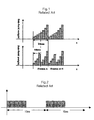
- Fig. 1 is graphs illustrating a related art PDP driving method.
- a frame driven at a frequency of a 50 Hz is shown.
- 50 Hz driving method is generally used in Europe and 60 Hz driving method is used in Republic of Korea, USA, etc.
- the related art PDP driving method includes dividing 20 ms frame driven at 50 Hz into two 10 ms frames driven at 100 Hz, and rearranging subfields included in each frame.
- 20 ms frame includes eight different subfields.
- a first frame of 10 ms consists of first, third, fifth and seventh subfields
- a second frame of 10 ms consists of second, fourth, sixth and eighth subfields.
- the driving method shown in Fig. 1 allows an XGA single scan PDP panel and a HD PDP panel to have a limitation in the number of subfields, it is difficult to apply the 100 Hz driving method to the XGA single scan PDP panel and the HD PDP panel. Also, the lack of the number of the subfields causes a serious quantization in a low gray scale region. Further, since one frame is divided into two frames, double false contour may be caused.
- Fig. 2 is a schematic view exemplarily showing a related art PDP driving method.
- the related art PDP driving method divides one 50 Hz frame into two 50 Hz frames.
- the driving method of Fig. 1 divides one 50 Hz frame into two 100 Hz frames
- the driving method of Fig. 2 divides one 50 Hz frame into two 50 Hz frames. Accordingly, in the driving method of Fig. 2, though one frame is divided into two frames, the driving method is maintained in 50 Hz driving without any change. In other words, one 50 Hz frame is divided into two 100 Hz frames, but since data can be displayed only during half of each frame, the 50 Hz frame is resultantly divided into two 50 Hz frames.
- the lowest brightness weight of the first frame (10 ms) is different than the lowest brightness weight of the second frame (10 ms), and the remaining brightness weights of the first frame are the same as those of the second frame.
- the first and second frames are arranged having symmetric brightness weights. Accordingly, large area flicker occurring in the 50 Hz driving can be minimized.
- the present invention is directed to a method for driving a plasma display panel using a 50 Hz driving.
- An object of the present invention is to provide a method for driving a plasma display panel that can prevent flicker and double false contour in a 50 Hz driving.
- a method for driving a plasma display panel using a 50 Hz driving including: providing a plurality of 50 Hz frames which are inputted using subfield weights for constructing a 60 Hz frame; and rearranging the plurality of 50 Hz frames into a plurality of 60 Hz frames.
- Each of the plurality of 60 Hz frames may have the same subfield weights.
- the subfield weights for constructing the 60 Hz frame may be obtained from the plurality of 50 Hz frames set on a mapping table.
- the plurality of 50 Hz input frames correspond to the plurality of 50 Hz frames set on the mapping table.
- a method for driving a plasma display panel at 50 Hz including: sequentially receiving a plurality of 50 Hz frames; rearranging the plurality of 50 Hz frames into a plurality of 60 Hz frames using a plurality of 50 Hz frame previously set on the mapping table; and expressing a gray scale according to the plurality of 60 Hz frames.
- Each of the plurality of 50 Hz frames set on the mapping table may include subfield weights constructing one 60 Hz frame and subfield weights constructing a part of other 60 Hz frames.
- Each of the plurality of 50 Hz frames set on the mapping table may include subfield weights constructing a part of one 60 Hz frame and subfield weights constructing a part of other 60 Hz frames.
- Fig. 1 is graphs illustrating a related art PDP driving method
- Fig. 2 is graphs illustrating another related art PDP driving method
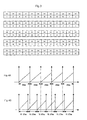
- Fig. 3 illustrates mapping tables including subfield weights according to an embodiment of the present invention.
- Figs. 4A and 4B illustrate a rearrangement of frames in a method for driving a plasma display panel according to the present invention.
- the present invention provides a method for driving a plasma display panel that can solve a flicker and a false contour, which occur in a 50 Hz driving method.
- a 50 Hz driving method According to the driving method of the present invention, five 50 Hz frames are rearranged into six 60 Hz frames.
- the driving method uses the 50 Hz driving method as it is and the frames are driven at 50 Hz.
- mapping tables corresponding to five 50 Hz frames may be provided on a memory within a system for driving a PDP.
- Fig. 3 is a view of mapping tables including subfield weights according to an embodiment of the present invention.
- Each mapping table includes frames assigned for 50 Hz driving. Accordingly, each mapping table has one 50 Hz frame. That is, a first frame driven at 50 Hz is set on a first mapping table, and a second frame driven at 50 Hz is set on a second mapping table. A third frame driven at 50 Hz is set on a third mapping table, and a fourth frame driven at 50 Hz is set on a fourth mapping table. Also, a fifth frame driven at 50 Hz is set on a fifth mapping table. Accordingly, the five frames driven at 50 Hz are received and a predetermined gray scale is expressed using the five frames with reference to the frames set on the respective mapping tables.
- the five 50 Hz frames are rearranged into the six 60 Hz frames.
- five frames driven at 50 Hz are rearranged into six frames driven at 60 Hz by using subfield weights set on the 50 Hz frames of the respective mapping tables.
- a period of 50 Hz frame is 20 ms
- a period of 60 Hz frame is 16.67 ms. If the five 50 Hz frames are rearranged into the six 60 Hz frames, the frame period is reduced as much such that a flicker and a double false contour seldom occur.
- the respective frames set on the mapping tables include twelve subfield weights. Accordingly, the five frames include a total of sixty subfield weights. At this time, subfield weights (1-2-4-4-8-16-30-35-40-45) capable of constructing one 60 Hz frame and subfield weights (1-2 or 40-45) capable of constructing a part of other 60 Hz frames are set on the first and fifth frames. Also, subfield weights capable of constructing a part of one 60 Hz frame and a part of other 60 Hz frames are set on the second to fourth frames.
- subfield weights (4-4-8-16-30-35-40-45-1-2-4-4) are set on the second frame
- subfield weights (8-16-30-35-40-45-1-2-4-4-8-16) are set on the third frames
- subfield weights (30-35-40-45-1-2-4-4-8-16-30-35) are set on the fourth frame.
- the first 50 Hz frame includes ten subfield weights (1-2-4-4-8-16-30-35-40-45) constructing the first 60 Hz frame, and two subfield weights (1-2) constructing the second 60 Hz frame.
- the second 50 Hz frame includes eight subfield weights (4-4-8-16-30-35-40-45) constructing the second 60 Hz frame, and four subfield weights (1-2-4-4) constructing the third 60 Hz frame.
- the third 50 Hz frame includes six subfield weights (8-16-30-35-40-45) constructing the third 60 Hz frame, and six subfield weights (1-2-4-4-8-16) constructing the fourth 60 Hz frame.
- the fourth 50 Hz frame includes four subfield weights (30-35-40-45) constructing the fourth 60 Hz frame, and eight subfield weights (1-2-4-4-8-16-30-35) constructing the fifth 60 Hz frame.
- the fifth 50 Hz frame includes two subfield weights (40-45) constructing the fifth 60 Hz frame, and ten subfield weights (1-2-4-4-8-16-30-35-40-45) constructing the sixth 60 Hz frame.
- the first and fifth 50 Hz frames includes all the subfield weights constructing the first and sixth 60 Hz frames.
- the remaining 60 Hz frames, the second to fifth 50 Hz frames can be constructed using the subfield weights set on the second to fourth 50 Hz frames.
- the first and sixth 60 Hz frames (1-2-4-4-8-16-30-35-40-45) are constructed from the first and fifth 50 Hz frames.
- the second 60 Hz frame is constructed by connecting a portion (1-2) of the first 50 Hz frame and a portion (4-4-8-16-30-35-40-45) of the second 50 Hz frame.
- the third 60 Hz frame is constructed by connecting a portion (1-2-4-4) of the second 50 Hz frame and a portion (8-16-30-35-40-45) of the third 50 Hz frame.
- the fourth 60 Hz frame is constructed by connecting a portion (1-2-4-4-8-16) of the third 50 Hz frame and a portion (30-35-40-45) of the fourth 50 Hz frame.
- the fifth 60 Hz frame is constructed by connecting a portion (1-2-4-4-8-16-30-35) of the fourth 50 Hz frame and a portion (40-45) of the fifth 50 Hz frame.
- the six 60 Hz frames having the ten subfield weights can be constructed with the five 50 Hz frames having the twelve subfield weights.
- the five 50 Hz frames are sequentially received.
- the five 50 Hz frames capable of constructed the six 60 Hz frames having ten subfield weights are set on the mapping tables.
- the six 60 Hz frames are constructed using the five 50 Hz frames set on the mapping tables. While the 50 Hz frame is constructed using twelve subfield weights, the 60 Hz frame can be constructed using ten 60 Hz frames.
- the first and sixth 60 Hz frames are constructed using the first and fifth 50 Hz frames, and the second to fourth 60 Hz frames are constructed using the second to fourth 50 Hz frames.
- a predetermined gray scale is expressed according to the six 60 Hz frames.
- Figs. 4A and 4B illustrate a driving method of the PDP according to the present invention, in which the frames are rearranged.
- Fig. 4A illustrates an arrangement of the five 50 Hz frames
- Fig. 4B illustrates the six 60 Hz frames rearranged from the five 50 Hz frames.
- each of the frames set on the mapping tables includes the twelve subfield weights.
- a desired gray scale is expressed by rearranging the mapping tables into the first to sixth 60 Hz frames, which are constructed with ten subfield weights, from the first to fifth frames having twelve subfield weights.
- the first 60 Hz frame is constructed using the first 50 Hz frame, which is inputted in response to the vertical synchronization signal (Vsync) and includes twelve subfield weights of the first mapping table.
- Vsync vertical synchronization signal
- the second 60 Hz frame is constructed using the first and second 50 Hz frames having twelve subfield weights set on the first and second mapping tables.
- the third 60 Hz frame is constructed using the second and third 50 Hz frames having twelve subfield weights set on the second and third mapping tables.
- each of the six 60 Hz frames has the equal arrangement of the subfield weights.
- the subfield weights of each 60 Hz frame may be arranged in order of 1-2-4-4-8-16-30-35-40-45.
- five 50 Hz frames are rearranged into six 60 Hz frames using the subfield weights which are previously set on have 60 Hz frames.
- the rearranged six 60 Hz frames are not driven at 60 Hz, but they can provide the same effect as the driving at 60 Hz. Accordingly, it is possible to prevent the flicker and the double false contour occurring in the conventional 50 Hz driving. Also, it is possible to obtain the same effect of the 60 Hz driving which is now used in U.S.A and Korea.
- six 60 Hz frames can be constructed using the subfield weights set on five 50 Hz frames.
- each of the 50 Hz frames of the mapping tables includes twelve subfield weights
- six subfield weights can be arbitrarily set on each of the five 50 Hz frames.
- six 60 Hz frames each having five subfield weights can be constructed using the five 50 Hz frames.
- the frame period is reduced from 20 ms to 16.67 ms by converting an optical center of 50 Hz into that of 60 Hz, thereby eliminating the flicker phenomenon.
Abstract
Description
- The present invention relates to a plasma display panel, and more particularly, to a method for driving a plasma display panel that can eliminate moving picture noise in a 50 Hz driving method.
- Recently, a plasma display panel (PDP), which is one of flat panel displays, is in the limelight because it is expected to be easily capable of realizing a large-sized panel. The PDP displays an image by controlling a discharge period of each pixel according to digital data. The discharge period may be determined by the number of sustain pulses having subfield weight.
- An alternate type PDP is a representative of such PDPs, and is provided with three electrodes and driven by an alternative voltage. The alternate type PDP is driven by an address-display separated (ADS) driving method so as to display an image. The ADS driving method can express a desired gray scale according to sequence of subfields, sub-field weight, and the number of sustain pulses.
- However, the ADS driving method may cause problems due to motion artifacts, large area flicker, and variation in the number of gray scales. The motion artifacts are caused by dynamic false contour and motion blurring. The dynamic false contour is due to non-linear method temporarily used for displaying gray scale, and the motion blurring is due to light emitting from each pixel during a time longer than an overall frame time.
- Fig. 1 is graphs illustrating a related art PDP driving method. In Fig. 1, a frame driven at a frequency of a 50 Hz is shown. 50 Hz driving method is generally used in Europe and 60 Hz driving method is used in Republic of Korea, USA, etc.
- As shown in Fig. 1, the related art PDP driving method includes dividing 20 ms frame driven at 50 Hz into two 10 ms frames driven at 100 Hz, and rearranging subfields included in each frame. For example, 20 ms frame includes eight different subfields. A first frame of 10 ms consists of first, third, fifth and seventh subfields, and a second frame of 10 ms consists of second, fourth, sixth and eighth subfields. Thus, when 20 ms frame driven at 50 Hz is modulated into two 10 ms frames driven at 100 Hz, large area flicker that is a large area screen flicker phenomenon occurring in the 50 Hz driving method can be prevented, and subfield weights accumulated on a retina by adjacent main frames in the 100 Hz driving are effectively dispersed thereby offsetting the dynamic false contour.
- However, since the driving method shown in Fig. 1 allows an XGA single scan PDP panel and a HD PDP panel to have a limitation in the number of subfields, it is difficult to apply the 100 Hz driving method to the XGA single scan PDP panel and the HD PDP panel. Also, the lack of the number of the subfields causes a serious quantization in a low gray scale region. Further, since one frame is divided into two frames, double false contour may be caused.
- Fig. 2 is a schematic view exemplarily showing a related art PDP driving method.
- As shown in Fig. 2, the related art PDP driving method divides one 50 Hz frame into two 50 Hz frames. In other words, the driving method of Fig. 1 divides one 50 Hz frame into two 100 Hz frames, whereas the driving method of Fig. 2 divides one 50 Hz frame into two 50 Hz frames. Accordingly, in the driving method of Fig. 2, though one frame is divided into two frames, the driving method is maintained in 50 Hz driving without any change. In other words, one 50 Hz frame is divided into two 100 Hz frames, but since data can be displayed only during half of each frame, the 50 Hz frame is resultantly divided into two 50 Hz frames.
- Thus, when 50 Hz frame is divided into two 50 Hz frames, the lowest brightness weight of the first frame (10 ms) is different than the lowest brightness weight of the second frame (10 ms), and the remaining brightness weights of the first frame are the same as those of the second frame. Also, the first and second frames are arranged having symmetric brightness weights. Accordingly, large area flicker occurring in the 50 Hz driving can be minimized.
- However, since the related art PDP driving method of Fig. 2 divides one frame into two frames, double false contour may be caused. In other words, the division of the first and second frames functions to change 50 Hz into 50 Hz, but since real data is identically repeated in two frames to reproduce a moving picture, so that double false contour occurs, thereby lowering video resolution.
- Accordingly, the present invention is directed to a method for driving a plasma display panel using a 50 Hz driving.
- An object of the present invention is to provide a method for driving a plasma display panel that can prevent flicker and double false contour in a 50 Hz driving.
- Additional advantages, objects, and features of the invention will be set forth in part in the description which follows and in part will become apparent to those having ordinary skill in the art upon examination of the following or may be learned from practice of the invention. The objectives and other advantages of the invention may be realized and attained by the structure particularly pointed out in the written description and claims hereof as well as the appended drawings.
- To achieve these objects and other advantages and in accordance with the purpose of the invention, as embodied and broadly described herein, there is provided a method for driving a plasma display panel using a 50 Hz driving, including: providing a plurality of 50 Hz frames which are inputted using subfield weights for constructing a 60 Hz frame; and rearranging the plurality of 50 Hz frames into a plurality of 60 Hz frames.
- Each of the plurality of 60 Hz frames may have the same subfield weights.
- The subfield weights for constructing the 60 Hz frame may be obtained from the plurality of 50 Hz frames set on a mapping table.
- Preferably, the plurality of 50 Hz input frames correspond to the plurality of 50 Hz frames set on the mapping table.
- When the plurality of 50 Hz input frames are five, six 60 Hz frames are obtained using the five 50 Hz frames set on the mapping table.
- According to another aspect of the present invention, there is provided a method for driving a plasma display panel at 50 Hz, the method including: sequentially receiving a plurality of 50 Hz frames; rearranging the plurality of 50 Hz frames into a plurality of 60 Hz frames using a plurality of 50 Hz frame previously set on the mapping table; and expressing a gray scale according to the plurality of 60 Hz frames.
- Each of the plurality of 50 Hz frames set on the mapping table may include subfield weights constructing one 60 Hz frame and subfield weights constructing a part of other 60 Hz frames. Each of the plurality of 50 Hz frames set on the mapping table may include subfield weights constructing a part of one 60 Hz frame and subfield weights constructing a part of other 60 Hz frames.
- It is to be understood that both the foregoing general description and the following detailed description of the present invention are exemplary and explanatory and are intended to provide further explanation of the invention as claimed.
- The accompanying drawings, which are included to provide a further understanding of the invention and are incorporated in and constitute a part of this application, illustrate embodiment(s) of the invention and together with the description serve to explain the principle of the invention. In the drawings:
- Fig. 1 is graphs illustrating a related art PDP driving method;
- Fig. 2 is graphs illustrating another related art PDP driving method;
- Fig. 3 illustrates mapping tables including subfield weights according to an embodiment of the present invention; and
- Figs. 4A and 4B illustrate a rearrangement of frames in a method for driving a plasma display panel according to the present invention.
- Reference will now be made in detail to the preferred embodiments of the present invention, examples of which are illustrated in the accompanying drawings.
- The present invention provides a method for driving a plasma display panel that can solve a flicker and a false contour, which occur in a 50 Hz driving method. According to the driving method of the present invention, five 50 Hz frames are rearranged into six 60 Hz frames. The driving method uses the 50 Hz driving method as it is and the frames are driven at 50 Hz.
- For this purpose, five mapping tables corresponding to five 50 Hz frames may be provided on a memory within a system for driving a PDP.
- Fig. 3 is a view of mapping tables including subfield weights according to an embodiment of the present invention.
- Referring to Fig. 3, five mapping tables are provided on a memory within a system for driving a PDP according to the present invention. Each mapping table includes frames assigned for 50 Hz driving. Accordingly, each mapping table has one 50 Hz frame. That is, a first frame driven at 50 Hz is set on a first mapping table, and a second frame driven at 50 Hz is set on a second mapping table. A third frame driven at 50 Hz is set on a third mapping table, and a fourth frame driven at 50 Hz is set on a fourth mapping table. Also, a fifth frame driven at 50 Hz is set on a fifth mapping table. Accordingly, the five frames driven at 50 Hz are received and a predetermined gray scale is expressed using the five frames with reference to the frames set on the respective mapping tables.
- According to the present invention, the five 50 Hz frames are rearranged into the six 60 Hz frames.
- For this purpose, five frames driven at 50 Hz are rearranged into six frames driven at 60 Hz by using subfield weights set on the 50 Hz frames of the respective mapping tables.
- Here, while a period of 50 Hz frame is 20 ms, a period of 60 Hz frame is 16.67 ms. If the five 50 Hz frames are rearranged into the six 60 Hz frames, the frame period is reduced as much such that a flicker and a double false contour seldom occur.
- The respective frames set on the mapping tables include twelve subfield weights. Accordingly, the five frames include a total of sixty subfield weights. At this time, subfield weights (1-2-4-4-8-16-30-35-40-45) capable of constructing one 60 Hz frame and subfield weights (1-2 or 40-45) capable of constructing a part of other 60 Hz frames are set on the first and fifth frames. Also, subfield weights capable of constructing a part of one 60 Hz frame and a part of other 60 Hz frames are set on the second to fourth frames. For example, subfield weights (4-4-8-16-30-35-40-45-1-2-4-4) are set on the second frame, subfield weights (8-16-30-35-40-45-1-2-4-4-8-16) are set on the third frames, and subfield weights (30-35-40-45-1-2-4-4-8-16-30-35) are set on the fourth frame.
- In more detail, the first 50 Hz frame includes ten subfield weights (1-2-4-4-8-16-30-35-40-45) constructing the first 60 Hz frame, and two subfield weights (1-2) constructing the second 60 Hz frame. The second 50 Hz frame includes eight subfield weights (4-4-8-16-30-35-40-45) constructing the second 60 Hz frame, and four subfield weights (1-2-4-4) constructing the third 60 Hz frame. The third 50 Hz frame includes six subfield weights (8-16-30-35-40-45) constructing the third 60 Hz frame, and six subfield weights (1-2-4-4-8-16) constructing the fourth 60 Hz frame. The fourth 50 Hz frame includes four subfield weights (30-35-40-45) constructing the fourth 60 Hz frame, and eight subfield weights (1-2-4-4-8-16-30-35) constructing the fifth 60 Hz frame. Finally, the fifth 50 Hz frame includes two subfield weights (40-45) constructing the fifth 60 Hz frame, and ten subfield weights (1-2-4-4-8-16-30-35-40-45) constructing the sixth 60 Hz frame. Accordingly, the first and fifth 50 Hz frames includes all the subfield weights constructing the first and sixth 60 Hz frames. The remaining 60 Hz frames, the second to fifth 50 Hz frames can be constructed using the subfield weights set on the second to fourth 50 Hz frames.
- In brief, the first and sixth 60 Hz frames (1-2-4-4-8-16-30-35-40-45) are constructed from the first and fifth 50 Hz frames. Also, the second 60 Hz frame is constructed by connecting a portion (1-2) of the first 50 Hz frame and a portion (4-4-8-16-30-35-40-45) of the second 50 Hz frame. The third 60 Hz frame is constructed by connecting a portion (1-2-4-4) of the second 50 Hz frame and a portion (8-16-30-35-40-45) of the third 50 Hz frame. The fourth 60 Hz frame is constructed by connecting a portion (1-2-4-4-8-16) of the third 50 Hz frame and a portion (30-35-40-45) of the fourth 50 Hz frame. The fifth 60 Hz frame is constructed by connecting a portion (1-2-4-4-8-16-30-35) of the fourth 50 Hz frame and a portion (40-45) of the fifth 50 Hz frame.
- Therefore, the six 60 Hz frames having the ten subfield weights can be constructed with the five 50 Hz frames having the twelve subfield weights.
- The driving method will now be described in brief.
- First, the five 50 Hz frames are sequentially received. At this time, the five 50 Hz frames capable of constructed the six 60 Hz frames having ten subfield weights are set on the mapping tables.
- Accordingly, the six 60 Hz frames are constructed using the five 50 Hz frames set on the mapping tables. While the 50 Hz frame is constructed using twelve subfield weights, the 60 Hz frame can be constructed using ten 60 Hz frames. For example, the first and sixth 60 Hz frames are constructed using the first and fifth 50 Hz frames, and the second to fourth 60 Hz frames are constructed using the second to fourth 50 Hz frames.
- A predetermined gray scale is expressed according to the six 60 Hz frames.
- Figs. 4A and 4B illustrate a driving method of the PDP according to the present invention, in which the frames are rearranged. In detail, Fig. 4A illustrates an arrangement of the five 50 Hz frames, and Fig. 4B illustrates the six 60 Hz frames rearranged from the five 50 Hz frames.
- Referring to Fig. 4A, if the frames are driven at 50 Hz, one frame is inputted at every one vertical synchronization signal (Vsync). The subfield weights of the frames set on the mapping tables are applied to express the gray scale on a screen. At this time, as shown in Fig. 3, each of the frames set on the mapping tables includes the twelve subfield weights. A desired gray scale is expressed by rearranging the mapping tables into the first to sixth 60 Hz frames, which are constructed with ten subfield weights, from the first to fifth frames having twelve subfield weights.
- According to the prior art, however, 50 Hz frames constructed with twelve subfield weights are set on the mapping tables. Accordingly, if 50 Hz frames are inputted, a desired gray scale is expressed using the subfield weights of the frames set on the mapping tables. However, if the frames are driven at 50 Hz in this manner, a flicker and a double false contour may occur.
- On the contrary, according to the present invention, when five 50 Hz frames are inputted, a desired gray scale is expressed through the rearrangement into six 60 Hz frames using five 50 Hz frames which are previously assigned so as to construct six 60 Hz frames. Referring to Fig. 4B, the first 60 Hz frame is constructed using the first 50 Hz frame, which is inputted in response to the vertical synchronization signal (Vsync) and includes twelve subfield weights of the first mapping table.
- Then, if the second 50 Hz frame is inputted, the second 60 Hz frame is constructed using the first and second 50 Hz frames having twelve subfield weights set on the first and second mapping tables.
- In a similar manner, if the third 50 Hz frame is inputted, the third 60 Hz frame is constructed using the second and third 50 Hz frames having twelve subfield weights set on the second and third mapping tables.
- Through these processes, if the fourth and fifth 50 Hz frames are inputted, the fourth 60 Hz frame is constructed using the third and fourth 50 Hz frames, and the fifth and sixth 60 Hz frames are constructed using the fourth and fifth 50 Hz frames. At this time, it is preferable that each of the six 60 Hz frames has the equal arrangement of the subfield weights. For example, as shown in Fig. 3, the subfield weights of each 60 Hz frame may be arranged in order of 1-2-4-4-8-16-30-35-40-45.
- According to the PDP driving method of the present invention, five 50 Hz frames are rearranged into six 60 Hz frames using the subfield weights which are previously set on have 60 Hz frames. At this time, the rearranged six 60 Hz frames are not driven at 60 Hz, but they can provide the same effect as the driving at 60 Hz. Accordingly, it is possible to prevent the flicker and the double false contour occurring in the conventional 50 Hz driving. Also, it is possible to obtain the same effect of the 60 Hz driving which is now used in U.S.A and Korea. As shown in Fig. 4B, six 60 Hz frames can be constructed using the subfield weights set on five 50 Hz frames.
- Although it has been described that each of the 50 Hz frames of the mapping tables includes twelve subfield weights, it is not always necessary for the 50 Hz frames to have twelve subfield weights so as to rearrange five 50 Hz frames into six 60 Hz frames. For example, six subfield weights can be arbitrarily set on each of the five 50 Hz frames. In this case, six 60 Hz frames each having five subfield weights can be constructed using the five 50 Hz frames.
- According to the PDP driving method of the present invention, the frame period is reduced from 20 ms to 16.67 ms by converting an optical center of 50 Hz into that of 60 Hz, thereby eliminating the flicker phenomenon.
- Also, it is possible to eliminate the double false contour occurring when 50 Hz frame is divided into two 100 Hz frames.
- Further, it is possible to the same effect as the 60 Hz driving method used in U.S.A by virtually constructing five 50 Hz frames with six 60 Hz frames, while maintaining the 50 Hz driving method used in Europe. The applications of products will be expanded because the flicker and the double false contour can be eliminated.
- It will be apparent to those skilled in the art that various modifications and variations can be made in the present invention. Thus, it is intended that the present invention covers the modifications and variations of this invention provided they come within the scope of the appended claims and their equivalents.
Claims (14)
- A method for driving a plasma display panel at 50 Hz, the method comprising:providing a plurality of 50 Hz frames which are inputted using subfield weights for constructing a 60 Hz frame; andrearranging the plurality of 50 Hz frames into a plurality of 60 Hz frames.
- The method according to claim 1, wherein each of the plurality of 60 Hz frames has the same subfield weights.
- The method according to claim 1, wherein the subfield weights for constructing the 60 Hz frame are obtained from the plurality of 50 Hz frames set on a mapping table.
- The method according to claim 3, wherein the plurality of 50 Hz input frames correspond to the plurality of 50 Hz frames set on the mapping table.
- The method according to claim 3, wherein when the plurality of 50 Hz input frames are five, six 60 Hz frames are obtained using the five 50 Hz frames set on the mapping table.
- The method according to claim 5, wherein a first 60 Hz frame is obtained from a first 50 Hz frame set on the mapping table.
- The method according to claim 5, wherein a sixth 60 Hz frame is obtained from a fifth 50 Hz frame set on the mapping table.
- The method according to claim 5, wherein second to fifth 60 Hz frames are obtained from second to fourth 50 Hz frames set on the mapping table.
- The method according to claim 5, wherein first to fifth 50 Hz frames set on the mapping table comprise subfield weights constructing one 60 Hz frame and subfield weights constructing a part of other 60 Hz frames.
- The method according to claim 5, wherein second to fourth 50 Hz frames set on the mapping table comprise subfield weights constructing a part of one 60 Hz frame and subfield weights constructing a part of other 60 Hz frames.
- A method for driving a plasma display panel at 50 Hz, the method comprising:sequentially receiving a plurality of 50 Hz frames;rearranging the plurality of 50 Hz frames into a plurality of 60 Hz frames using a plurality of 50 Hz frame previously set on the mapping table; andexpressing a gray scale according to the plurality of 60 Hz frames.
- The method according to claim 11, wherein the plurality of 50 Hz input frames correspond to the plurality of 50 Hz frames set on the mapping table.
- The method according to claim 11, wherein each of the plurality of 50 Hz frames set on the mapping table comprises subfield weights constructing one 60 Hz frame and subfield weights constructing a part of other 60 Hz frames.
- The method according to claim 11, wherein each of the plurality of 50 Hz frames set on the mapping table comprises subfield weights constructing a part of one 60 Hz frame and subfield weights constructing a part of other 60 Hz frames.
Applications Claiming Priority (2)
| Application Number | Priority Date | Filing Date | Title |
|---|---|---|---|
| KR1020030061653A KR100540228B1 (en) | 2003-09-04 | 2003-09-04 | Method for driving a plasma display panel |
| KR2003061653 | 2003-09-04 |
Publications (2)
| Publication Number | Publication Date |
|---|---|
| EP1513131A2 true EP1513131A2 (en) | 2005-03-09 |
| EP1513131A3 EP1513131A3 (en) | 2008-02-27 |
Family
ID=34132231
Family Applications (1)
| Application Number | Title | Priority Date | Filing Date |
|---|---|---|---|
| EP04077510A Withdrawn EP1513131A3 (en) | 2003-09-04 | 2004-09-06 | Method for driving plasma display panel |
Country Status (5)
| Country | Link |
|---|---|
| US (1) | US7688288B2 (en) |
| EP (1) | EP1513131A3 (en) |
| JP (1) | JP2005084685A (en) |
| KR (1) | KR100540228B1 (en) |
| CN (1) | CN1591542A (en) |
Citations (5)
| Publication number | Priority date | Publication date | Assignee | Title |
|---|---|---|---|---|
| EP0851400A1 (en) | 1996-12-25 | 1998-07-01 | Nec Corporation | Plasma display system |
| JPH10304281A (en) | 1997-05-02 | 1998-11-13 | Fujitsu Ltd | Gradation display method |
| DE19859678C1 (en) | 1998-12-23 | 2000-03-16 | Grundig Ag | Method and device for synchronizing image repeat or display frequency generated by a circuit for creating digital image signals for a flat screen uses a series of impulses. |
| EP1024663A2 (en) | 1999-01-29 | 2000-08-02 | Canon Kabushiki Kaisha | Image processing device |
| US6243073B1 (en) | 1996-12-06 | 2001-06-05 | Matsushita Electric Industrial Co., Ltd. | Video display monitor |
Family Cites Families (5)
| Publication number | Priority date | Publication date | Assignee | Title |
|---|---|---|---|---|
| JP2962245B2 (en) * | 1996-10-23 | 1999-10-12 | 日本電気株式会社 | Display device gradation display method |
| US6707502B1 (en) | 1999-04-28 | 2004-03-16 | Sony Corporation | Apparatus and method for converting a field frequency of a picture signal |
| US7098876B2 (en) * | 2001-09-06 | 2006-08-29 | Samsung Sdi Co., Ltd. | Image display method and system for plasma display panel |
| KR100480152B1 (en) * | 2002-05-17 | 2005-04-06 | 엘지전자 주식회사 | Method for driving of plasma display panel |
| JP2004274219A (en) * | 2003-03-06 | 2004-09-30 | Pioneer Electronic Corp | Frame rate conversion apparatus for video signal |
-
2003
- 2003-09-04 KR KR1020030061653A patent/KR100540228B1/en not_active IP Right Cessation
-
2004
- 2004-09-02 US US10/932,144 patent/US7688288B2/en not_active Expired - Fee Related
- 2004-09-03 CN CNA2004100742120A patent/CN1591542A/en active Pending
- 2004-09-03 JP JP2004256500A patent/JP2005084685A/en active Pending
- 2004-09-06 EP EP04077510A patent/EP1513131A3/en not_active Withdrawn
Patent Citations (5)
| Publication number | Priority date | Publication date | Assignee | Title |
|---|---|---|---|---|
| US6243073B1 (en) | 1996-12-06 | 2001-06-05 | Matsushita Electric Industrial Co., Ltd. | Video display monitor |
| EP0851400A1 (en) | 1996-12-25 | 1998-07-01 | Nec Corporation | Plasma display system |
| JPH10304281A (en) | 1997-05-02 | 1998-11-13 | Fujitsu Ltd | Gradation display method |
| DE19859678C1 (en) | 1998-12-23 | 2000-03-16 | Grundig Ag | Method and device for synchronizing image repeat or display frequency generated by a circuit for creating digital image signals for a flat screen uses a series of impulses. |
| EP1024663A2 (en) | 1999-01-29 | 2000-08-02 | Canon Kabushiki Kaisha | Image processing device |
Also Published As
| Publication number | Publication date |
|---|---|
| US7688288B2 (en) | 2010-03-30 |
| CN1591542A (en) | 2005-03-09 |
| KR100540228B1 (en) | 2006-01-10 |
| KR20050024799A (en) | 2005-03-11 |
| EP1513131A3 (en) | 2008-02-27 |
| US20050052360A1 (en) | 2005-03-10 |
| JP2005084685A (en) | 2005-03-31 |
Similar Documents
| Publication | Publication Date | Title |
|---|---|---|
| US6714250B1 (en) | Method and apparatus for processing video pictures, in particular for large area flicker effect reduction | |
| US7420576B2 (en) | Display apparatus and display driving method for effectively eliminating the occurrence of a moving image false contour | |
| US6476875B2 (en) | Method and apparatus for processing video pictures, especially for false contour effect compensation | |
| KR100318647B1 (en) | Gradation display system | |
| US6473464B1 (en) | Method and apparatus for processing video pictures, especially for false contour effect compensation | |
| EP0982708A1 (en) | Method and apparatus for processing video pictures, in particular for large area flicker effect reduction | |
| EP1450338A3 (en) | Method and device for displaying an image on a plasma display panel with subfield arrangement dependent on the load ratio of the input video signal | |
| JP3518949B2 (en) | Display device | |
| KR20020096821A (en) | Pdp driving method and display device | |
| JPH10171401A (en) | Gradation display method | |
| US6717558B1 (en) | Method for processing video pictures for display on a display device and apparatus for carrying out the method | |
| JP4152153B2 (en) | Image display method and apparatus for plasma display panel | |
| JP4991066B2 (en) | Method and apparatus for processing video images | |
| US7391391B2 (en) | Display apparatus | |
| JP2001125529A (en) | Method for displaying gradation and display device | |
| JPH09258688A (en) | Display device | |
| EP2105913A2 (en) | Method and apparatus to drive plasma display device | |
| EP1058229B1 (en) | Method and apparatus for processing video signals for display | |
| US7688288B2 (en) | Method for driving plasma display panel | |
| JP3521591B2 (en) | Error diffusion processing device for display device | |
| KR100420032B1 (en) | A method for displaying pictures on plasma display panel and an apparatus thereof | |
| KR20050015286A (en) | A method for displaying pictures on plasma display panel and an apparatus thereof | |
| JP3656995B2 (en) | Image display method and image display apparatus | |
| JP2001042819A (en) | Method and device for gradation display | |
| JPH11288240A (en) | Method and circuit for driving display device |
Legal Events
| Date | Code | Title | Description |
|---|---|---|---|
| PUAI | Public reference made under article 153(3) epc to a published international application that has entered the european phase |
Free format text: ORIGINAL CODE: 0009012 |
|
| AK | Designated contracting states |
Kind code of ref document: A2 Designated state(s): AT BE BG CH CY CZ DE DK EE ES FI FR GB GR HU IE IT LI LU MC NL PL PT RO SE SI SK TR |
|
| AX | Request for extension of the european patent |
Extension state: AL HR LT LV MK |
|
| RIN1 | Information on inventor provided before grant (corrected) |
Inventor name: HYEON, CHANG HO,319 DOONJEON-RI Inventor name: SONG, BYUNG SOO507-201 GYEONYOUNG BILLA |
|
| RIN1 | Information on inventor provided before grant (corrected) |
Inventor name: HYEON, CHANG HO,104-203 INJEONG MELODY APT. Inventor name: SONG, BYUNG SOO507-201 GYEONYOUNG BILLA |
|
| PUAL | Search report despatched |
Free format text: ORIGINAL CODE: 0009013 |
|
| AK | Designated contracting states |
Kind code of ref document: A3 Designated state(s): AT BE BG CH CY CZ DE DK EE ES FI FR GB GR HU IE IT LI LU MC NL PL PT RO SE SI SK TR |
|
| AX | Request for extension of the european patent |
Extension state: AL HR LT LV MK |
|
| 17P | Request for examination filed |
Effective date: 20080825 |
|
| AKX | Designation fees paid |
Designated state(s): DE FR NL |
|
| 17Q | First examination report despatched |
Effective date: 20081104 |
|
| STAA | Information on the status of an ep patent application or granted ep patent |
Free format text: STATUS: THE APPLICATION IS DEEMED TO BE WITHDRAWN |
|
| 18D | Application deemed to be withdrawn |
Effective date: 20100401 |