EP1513031A1 - Uhr mit zwei relativ zueinander drehenden Uhrgehäusen - Google Patents
Uhr mit zwei relativ zueinander drehenden Uhrgehäusen Download PDFInfo
- Publication number
- EP1513031A1 EP1513031A1 EP04020747A EP04020747A EP1513031A1 EP 1513031 A1 EP1513031 A1 EP 1513031A1 EP 04020747 A EP04020747 A EP 04020747A EP 04020747 A EP04020747 A EP 04020747A EP 1513031 A1 EP1513031 A1 EP 1513031A1
- Authority
- EP
- European Patent Office
- Prior art keywords
- boxes
- box
- drive
- rotation
- transmission
- Prior art date
- Legal status (The legal status is an assumption and is not a legal conclusion. Google has not performed a legal analysis and makes no representation as to the accuracy of the status listed.)
- Granted
Links
- 230000007246 mechanism Effects 0.000 claims abstract description 36
- 230000005540 biological transmission Effects 0.000 claims description 38
- 238000006073 displacement reaction Methods 0.000 description 6
- 238000007789 sealing Methods 0.000 description 2
- PEDCQBHIVMGVHV-UHFFFAOYSA-N Glycerine Chemical compound OCC(O)CO PEDCQBHIVMGVHV-UHFFFAOYSA-N 0.000 description 1
- 210000005069 ears Anatomy 0.000 description 1
- 230000000694 effects Effects 0.000 description 1
- 230000014759 maintenance of location Effects 0.000 description 1
- 238000012986 modification Methods 0.000 description 1
- 230000004048 modification Effects 0.000 description 1
- 210000000056 organ Anatomy 0.000 description 1
- 230000001105 regulatory effect Effects 0.000 description 1
- 230000000717 retained effect Effects 0.000 description 1
- 230000002441 reversible effect Effects 0.000 description 1
- 238000010079 rubber tapping Methods 0.000 description 1
- 235000012046 side dish Nutrition 0.000 description 1
- 238000004513 sizing Methods 0.000 description 1
Images

Classifications
-
- G—PHYSICS
- G04—HOROLOGY
- G04B—MECHANICALLY-DRIVEN CLOCKS OR WATCHES; MECHANICAL PARTS OF CLOCKS OR WATCHES IN GENERAL; TIME PIECES USING THE POSITION OF THE SUN, MOON OR STARS
- G04B37/00—Cases
- G04B37/04—Mounting the clockwork in the case; Shock absorbing mountings
- G04B37/0427—Mountings relative to pocket and wrist watches allowing a rocking movement about a hinge or any other movement
Definitions
- the present invention relates to a timepiece comprising a body forming box inside which is housed a watch movement, this body having at least two distinct faces on which are arranged respectively first and second display means driven by the watch movement.
- a timepiece comprising first and second boxes (an upper box and a lower box) mounted pivoting relative to each other about a substantially perpendicular pivot axis in the general plan of boxes. Both boxes can occupy a first position closed where the upper box is superimposed on the lower box and hides the face before the lower box, and a second open position where the upper box is rotated relative to the lower box to discover the front. It's about however here a timepiece where the upper box has a movement watchmaker and associated means for displaying the time and where the lower box has a compass. It will be understood that the watch movement is fully mounted in the upper box and is totally independent of the mechanism housed in the lower box, namely the compass.
- a general object of the present invention is to propose a solution allowing, like the previous solutions, to exploit a larger surface on the timepiece to equip it with a wide range of display means, while ensuring however a great simplicity of handling, especially avoiding the need to return the body forming box.
- Another object of the present invention is to propose a solution which requires a unique watchmaking movement that can otherwise be entirely realized in mechanical form.
- the subject of the present invention is a timepiece whose features are set forth in claim 1.
- the body forming the box of the timepiece thus comprises a first box, said upper box, having a front face comprising the first display means and a second box, said lower box, having a face before comprising the second display means.
- These boxes are mounted pivoting relative to each other about a pivot axis substantially perpendicular to the general plane of the boxes and can occupy a first position, said closed, where the upper box is superimposed on the lower box and mask on the less in part the front of the lower box, and a second position, called open, where the upper box is rotated laterally relative to the box lower to discover at least a portion of the front face.
- Movement watchmaker comprises first and second parts housed respectively in the upper and lower boxes to drive the first and second means display, respectively, and a drive mechanism providing a link kinematic between the first and second parts of the watch movement.
- this drive mechanism is arranged to provide an interruption of the kinematic connection between the first and second parts of the movement watchmaker when the boxes are brought into the open position.
- the watch movement is subdivided into two parts which are respectively housed in the upper and lower boxes, the drive mechanism being provided to ensure a kinematic connection between these two parts of the movement watchmaker and to interrupt this kinematic link when the boxes are brought into open position.
- the drive mechanism comprises a transmission mobile axis confused with the pivot axis of the boxes, this transmission mobile comprising a first end located in the upper box and a second end located in the lower box.
- the boxes are brought in open position by rotation of the upper box relative to the lower box according to a first determined direction of rotation and the transmission mobile is driven in rotation by the watch movement according to a second direction of rotation opposite to the first direction of rotation, the drive mechanism being arranged to interrupt the rotational drive of the transmission mobile when the boxes are brought in the open position and to restore the rotational drive of the mobile of transmission when the boxes are brought back in the closed position.
- the mechanism of training is moreover arranged to make up for a synchronism error (or delay) between the first and second display means when the boxes are brought back to the closed position.
- the timepiece further comprises a retaining element of essentially tubular shape, of axis coinciding with the axis of pivoting boxes and crossed by the aforementioned mobile transmission, this retaining element being secured to one of the boxes and now axially the other box along the pivot axis while allowing rotation of this other box relative to the retainer.
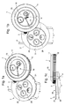
- FIGS. 1a to 1c generally illustrate a timepiece presenting itself in the general form of a wristwatch and constituting an embodiment preferred embodiment of the present invention.
- the body forming the box of the timepiece consists of two boxes 1 and 2, respectively designated box upper and lower box, each carrying on their front face means displayed generally by numbers 16 and 26 respectively.
- These two boxes 1, 2 are capable of pivoting relative to each other about an axis of pivoting, designated X, substantially perpendicular to the general plane of the two boxes 1 and 2.
- the boxes upper 1 and lower 2 can occupy a first position, said closed, (not shown) where the upper box 1 is superimposed on the lower box 2 and hides the front of this box, and a second position, called open (position shown in Figures 1a to 1c) where the upper box 1 is rotated relative to the lower box 2 to discover at least part of the front face where the second display means 26 are.
- the lower box 2 is conventionally provided with horns 4 to allow the attachment of a bracelet represent.
- the upper box 1 is in turn conventionally provided with a crown rod 3 to allow the time setting of the timepiece.
- the first ones display means 16 formed on the front face of the upper box 1 conventionally include needles hours and minutes arranged in the center and supplemented by others indicators, for example a seconds indicator or a reserve indicator of walk.
- the second display means 26 formed on the front face of the box lower 2 include in particular a moon phase indicator and an indicator of calendars. These second display means 26 are generally arranged in eccentric position on the front of the lower box 2.
- the hands of the hours and minutes may for example be arranged on the front face of the lower box 2.
- These needles will typically be placed on the box in which the source is housed. of mechanical energy (barrel and mainspring) and the regulating devices of the movement of the timepiece (balance spring and escapement), these parts can be arranged independently in the upper box 1 or lower 2.
- the presence of the crown rod 3 and the hour and minute hands on the box superior 1 suggests that these organs are arranged in the upper box 1.
- the watch movement is, strictly speaking, divided into two parts (no represented in FIGS. 1a to 1c) housed respectively in the boxes upper and lower 2 (these parts are hereinafter referred to generally as numerals 100 and 200 respectively), a drive mechanism being provided to ensure a kinematic connection between these two parts of the movement.
- This mechanism of training will be described in more detail in the following this description.
- this pivot point is advantageously arranged inside the outer circumference of the two boxes 1, 2, no ears or unsightly protuberance thus not being visible on the periphery of the boxes.
- the pivot axis X is essentially in the quadrant between midday and three hours (here substantially at two hours), the second display means 26 being slightly eccentric towards the lower left part of the front face of the lower box 2.
- the boxes 1, 2 are brought into the open position by rotation of the upper box 1 in a direction of rotation determined around the axis of X.
- This direction of opening is indicated in Figure 1b by an arrow bearing the reference A, this sense of opening being here counter-clockwise (by convention this direction of rotation is defined around the pivot axis X, display means 16, 26 directed forward).
- the upper box 1 is rotated about 180 ° with respect to its closed position where it is superimposed on the lower box 2 to form together a body having the appearance of a usual watch box.
- a rotation limiting mechanism is preferably provided for guiding the boxes 1, 2 and limit their opening angle.
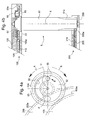
- FIG. 2 shows a partial sectional view passing through the pivot axis X boxes 1, 2 of the timepiece illustrated in Figures 1a to 1c.
- the upper box 1 formed of a bezel 11 carrying the ice 15 adjusted on a bottom portion 12
- the lower box 2 formed analogously of a bezel 21 carrying the ice 25 ( Figure 1a) fitted on a bottom portion 22.
- the FIG. 2 also shows part of a dial 17 disposed under the window 15 and the eyes of which turn the hands of the first display means 16.
- the sealing between the bezel 11 and the bottom 12, and between the bezel 21 and the bottom 22 is ensured typically by a seal 13, respectively 23, arranged in a groove formed on the bottom 12, resp. 22.
- the bottom 12 of the upper box 1 and the bezel 21 of the lower box 2 comprise an opening arranged to allow the passage of the mechanism drive ensuring the kinematic connection between the two parts 100, 200 of the watch movement.
- This training mechanism is designated globally by the No. 5 and is illustrated in greater detail in Figures 4a and 4b which will be discussed hereinafter. According to the illustrated embodiment, it will already be noted that the mechanism 5 includes a transmission unit 51, one of which end emerges in the upper box 1 and from which another end emerges in the lower box 2.
- the pivoting and the mechanical connection between the upper boxes 1 and 2 are preferably provided by means of a shape retaining member tubular 30 whose axis coincides with the axis of pivoting X boxes 1, 2 and through which passes the transmission mobile 51.
- This retaining element 30 is made integral with one of the boxes (here the upper box 1) for example by screwing, as illustrated, or by any other suitable means.
- the element of retainer 30 thus has a threaded end 30a cooperating with a tapping arranged in the bottom 12 of the upper box 1.
- the lower box 2 is retained axially along the pivot axis X via a span 30b arranged on the other end of the element 30. In this case, the telescope 21 of the lower box 2 is held axially between the span 30b and the bottom 12 of the upper box 1.
- the retaining element 30 advantageously forms the inner ring of a ball bearing 31 whose outer ring 32 is secured to of the lower box 2. It will be understood that this configuration makes it possible to reduce the friction between the contact areas of the two boxes during operations opening and closing of the two boxes. As an alternative, as illustrated in Figure 3, it is perfectly possible not to make use of a bearing to balls and to directly provide a radial clearance between the retainer 30 and the box lower 2.
- retaining element 30 could alternatively be made integral with the lower box 2 and that the pivoting of two boxes could be ensured by rotation between the retaining element 30 and the upper box 1.
- FIGS. 2 and 3 From a mechanical point of view and from the point of view of the sealing at the level of the pivot axis X, it is preferable, as illustrated in FIGS. 2 and 3, to arrange on one of the boxes at least one ring-shaped protuberance cooperating with an orifice or an annular groove of corresponding diameter on the other box.
- the bottom 12 of the upper box 1 is thus provided with such a protuberance designated by the numeral 12a cooperating with a corresponding orifice, designated 21a, formed in the bezel 21 of the lower box 2.
- the telescope 21 is again provided with a annular protuberance 21b housed in an annular groove corresponding 12b formed in the bottom 12.
- the seal between the two boxes 1 and 2 is provided by an annular seal 33 radially interposed between the protuberance 12a and the wall of the orifice 21a.
- This seal ring 33 is in this case arranged in a groove in the wall of the orifice 21 a. It is obvious that the annular seal 33 could alternatively be housed in a groove formed around the protuberance 12a.
- FIG. 2a is a partial sectional view of the timepiece, according to cutting planes generally perpendicular to the pivot axis X, according to the A-A cut line shown in Figure 2. It contains the bottom 12 of the box upper 1 and the bezel 21 of the lower box 2 and the protuberances rings 12a and 21b formed respectively on the bottom 12 and the telescope 21. also found in section the retaining element 30 and its threaded end 30a secured to the bottom 12 by screwing, as well as the transmission unit 51 of the drive mechanism 5. Finally we find partially the ball bearing with its outer ring 32.
- the base of the retaining element 30 where is provided the span 30b advantageously comprises two side dishes 30c diametrically opposed, the purpose of which is to enable and facilitate the screwing of the retaining element 30 in the bottom 12 of the upper box 1, this operation of screwing being operated here before mounting the bottom 22 of the lower box 2.
- the pin 61 in the closed position the pin 61 is in abutment with a first end 62a of the groove and in the open position this pin 61 is brought into abutment with the other end 62b of the groove 62, the pin 61 thus moving in the groove 62 as indicated by the arrow C.
- the limiting pin 61 can be made integral with the bottom 12 and a groove is formed in the bezel 21. Other rotation limitation mechanisms may still be considered.
- FIG. 4a we find against the mobile transmission 51 already mentioned whose axis of rotation coincides with the pivot axis X of the boxes 1, 2.
- FIG. 4a we also indicated by arrow A the direction of rotation followed by the upper box 1 at the opening (by convention, we will consider that the opening is operated then that the display means 16, 26 face the observer) and the arrow B, the direction normal rotation of the mobile transmission 51 when it is driven by the watch movement.
- the drive mechanism 5 further comprises a drive wheel 53, a plate 52 as well as connecting means 55, 56 interposed between the wheel 53 and the plate 52.
- the drive wheel 53 and the plate 52 are coaxially mounted to the transmission mobile 51 and are arranged with the means link 55, 56 on one end of the transmission wheel 51 located here in the upper box 1.
- the other end of the transmission mobile 51 is located in the lower box 2.
- the mobile of transmission 51 is mounted between a bridge 120 of the first part 100 of the movement located in the upper box 1 and a bridge 220 of the second part 200 of the movement in the lower box 2.
- Numerals 110 and 210 designate additional bridges or plates of the two parts 100 and 200 of the movement.
- the plate 52 is fixedly secured to the transmission unit 51 while the drive wheel 53 is mounted free to rotate around the mobile of transmission 51. It can be seen here that the drive wheel 53 is held axially between the plate 52 and a bearing (not referenced) formed on the mobile of transmission 51.
- the drive wheel 53 is permanently engaged with the first part 100 of the clock movement, housed in the upper box 1.
- Figures 4a and 4b only illustrated a drive wheel 105 forming part of the first part 100 of the watch movement with its teeth 105a engaged with the teeth 53a of the drive wheel 53. It will therefore be understood that the drive wheel 53 is continually rotated under the effect of the first part 100 of the watch movement, the drive of this wheel 53 being effected in the direction of the arrow B.
- the transmission mobile 51 is in direct contact with the second part 200 of the watch movement.
- the transmission mobile 51 is terminated by a pinion part 51 has a direct engagement with the toothing 205a of a wheel 205 part of the second part 200 of the watch movement, located in the box lower 2.
- connection means 55, 56 between the plate 52 and the drive wheel 53 are arranged so that the plate 52 is normally rotated by the wheel drive 53 when the boxes 1, 2 occupy the closed position and so that the drive in rotation of the plate 52 by the wheel 53 is interrupted when the boxes are brought into position opened.
- the drive wheel 53 carries a pin 55 disposed in eccentric position with respect to the axis of X-pivoting and one end of which is slidably engaged in a groove 56 formed in the plate 52 and which has a circular arc pattern.
- the pin 55 could alternatively be placed on the tray 52 and the groove 56 formed on the drive wheel 53.
- the drive in rotation of the plate 52 by the drive wheel 53 is ensured by stop the pin 55 against one end of the groove 56 as is clearly illustrated in Figure 4a.
- the pin 55 is displaced in the groove 56, thus interrupting the stop of the pin 55 against the end of the groove 56.
- the pin 55 When opening and closing the boxes, the pin 55 undergoes a angular displacement corresponding to the opening angle of the boxes in one direction then in the other.
- the opening and closing operations do not therefore lead to final no delay or loss of synchronism between the first and second means 16 and 26.
- the delay is due only to the time that has elapsed since the interruption of the kinematic link and this delay is totally caught up during the closing due to the relative angular displacement of the pin 55 relative to the groove 56.
- the plate 52 and the transmission mobile 51 will undergo during of the closure a forced angular displacement that is equivalent to the angle opening boxes, that is to say 180 ° in this example.
- groove 56 is chosen for allow the pin to move when opening the boxes without coming in contact with the other end of the groove 56.
- the groove 56 has a development angle greater than the opening angle of the boxes 1, 2.
- the plate 52 and the transmission mobile 51 will be partially driven when opening boxes in a direction of rotation opposite to their normal direction of rotation, which is not advisable.
- the angle of development of the groove 56 is slightly greater than the opening angle of the boxes, fixed here at 180 °.
- the maximum interruption time of the kinematic link between the two parts 100, 200 of the movement depends on the sizing of the mobiles of the movement and drive mechanism 5 and can be fixed at will to a few minutes or hours. It should be mentioned that the angular displacement forced as well as the constraints on the teeth of the mobiles during the closing are not a real problem.
Landscapes
- Physics & Mathematics (AREA)
- General Physics & Mathematics (AREA)
- Electromechanical Clocks (AREA)
Priority Applications (1)
| Application Number | Priority Date | Filing Date | Title |
|---|---|---|---|
| EP20040020747 EP1513031B1 (de) | 2003-09-08 | 2004-09-01 | Uhr mit zwei relativ zueinander drehenden Uhrgehäusen |
Applications Claiming Priority (3)
| Application Number | Priority Date | Filing Date | Title |
|---|---|---|---|
| EP03077820 | 2003-09-08 | ||
| EP03077820A EP1513030A1 (de) | 2003-09-08 | 2003-09-08 | Uhr mit zwei relativ zueinander drehenden Uhrgehäusen |
| EP20040020747 EP1513031B1 (de) | 2003-09-08 | 2004-09-01 | Uhr mit zwei relativ zueinander drehenden Uhrgehäusen |
Publications (2)
| Publication Number | Publication Date |
|---|---|
| EP1513031A1 true EP1513031A1 (de) | 2005-03-09 |
| EP1513031B1 EP1513031B1 (de) | 2010-02-10 |
Family
ID=34137589
Family Applications (1)
| Application Number | Title | Priority Date | Filing Date |
|---|---|---|---|
| EP20040020747 Expired - Lifetime EP1513031B1 (de) | 2003-09-08 | 2004-09-01 | Uhr mit zwei relativ zueinander drehenden Uhrgehäusen |
Country Status (1)
| Country | Link |
|---|---|
| EP (1) | EP1513031B1 (de) |
Cited By (2)
| Publication number | Priority date | Publication date | Assignee | Title |
|---|---|---|---|---|
| EP2216693A1 (de) | 2009-02-10 | 2010-08-11 | CompliTime SA | Uhr |
| CN113467216A (zh) * | 2021-06-30 | 2021-10-01 | 深圳市喜丽时钟表文化传播有限公司 | 一种防尘防水高效防护的按钮及手表 |
Citations (1)
| Publication number | Priority date | Publication date | Assignee | Title |
|---|---|---|---|---|
| CH655633GA3 (en) * | 1984-07-03 | 1986-05-15 | Wristwatch including a compass |
-
2004
- 2004-09-01 EP EP20040020747 patent/EP1513031B1/de not_active Expired - Lifetime
Patent Citations (1)
| Publication number | Priority date | Publication date | Assignee | Title |
|---|---|---|---|---|
| CH655633GA3 (en) * | 1984-07-03 | 1986-05-15 | Wristwatch including a compass |
Cited By (4)
| Publication number | Priority date | Publication date | Assignee | Title |
|---|---|---|---|---|
| EP2216693A1 (de) | 2009-02-10 | 2010-08-11 | CompliTime SA | Uhr |
| WO2010092002A1 (fr) | 2009-02-10 | 2010-08-19 | Complitime Sa | Pièce d'horlogerie |
| US8477567B2 (en) | 2009-02-10 | 2013-07-02 | Complitime Sa | Timepiece |
| CN113467216A (zh) * | 2021-06-30 | 2021-10-01 | 深圳市喜丽时钟表文化传播有限公司 | 一种防尘防水高效防护的按钮及手表 |
Also Published As
| Publication number | Publication date |
|---|---|
| EP1513031B1 (de) | 2010-02-10 |
Similar Documents
| Publication | Publication Date | Title |
|---|---|---|
| EP1513030A1 (de) | Uhr mit zwei relativ zueinander drehenden Uhrgehäusen | |
| EP1564607B1 (de) | Vorrichtung zum Kroneschütz für eine Uhr | |
| EP3483664A1 (de) | Uhrmechanismus zum anzeigen des mondtags und der mondphase mit korrektursystem mit doppeltem antriebsstrang | |
| EP1728128B1 (de) | Uhr mit zwei drehbaren kronen | |
| EP3857313B1 (de) | Anzeigemechanismus mit einem einzigen fensterchen | |
| EP1680715B1 (de) | Uhr mit umkehrbarem uhrgehäuse | |
| EP1684135A1 (de) | Uhrgehäuse mit drehbarem Deckel-Aussenring | |
| EP4047423A1 (de) | Armbanduhr, die mit einer verriegelungsvorrichtung eines externen steuerorgans ausgestattet ist | |
| CH702841A1 (fr) | Dispositif correcteur multifonction et pièce d'horlogerie comprenant un tel dispositif correcteur. | |
| EP1513031B1 (de) | Uhr mit zwei relativ zueinander drehenden Uhrgehäusen | |
| EP2010972B1 (de) | Uhr mit einem durch einen drehbaren aussenring gesteurten zeigereinstellmechanismus | |
| EP2615503B1 (de) | Steuermechanismus eines Federhaus für Uhrwerk | |
| CH700958B1 (fr) | Montre à mouvement mobile. | |
| CH684814B5 (fr) | Pièce d'horlogerie pourvue d'un tour d'heures à présentation modifiable. | |
| CH713649B1 (fr) | Pièce d'horlogerie comprenant un dispositif de cache amovible pour organe réglant d'un mouvement horloger. | |
| CH700657B1 (fr) | Montre mystérieuse. | |
| CH718371A2 (fr) | Montre munie d'un dispositif de verrouillage d'un organe de commande extérieur. | |
| CH700531B1 (fr) | Pièce d'horlogerie. | |
| EP4300212B1 (de) | Modulare armbanduhr | |
| CH697073A5 (fr) | Dispositif protège-couronne pour montre-bracelet. | |
| CH720021B1 (fr) | Boite pour pièce d'horlogerie comportant une lunette tournante externe commandant un mobile d'affichage interne. | |
| CH701406B1 (fr) | Montre-bracelet comportant un module d'affichage. | |
| CH714320A2 (fr) | Mécanisme horloger d'affichage du jour lunaire et de la phase de lune, avec système de correction à double chaîne cinématique. | |
| WO2024178518A1 (fr) | Dispositif d'affichage de réserve de marche pour pièce d'horlogerie | |
| EP1396765A1 (de) | Weltzeituhr mit Weckermechanismus |
Legal Events
| Date | Code | Title | Description |
|---|---|---|---|
| PUAI | Public reference made under article 153(3) epc to a published international application that has entered the european phase |
Free format text: ORIGINAL CODE: 0009012 |
|
| AK | Designated contracting states |
Kind code of ref document: A1 Designated state(s): AT BE BG CH CY CZ DE DK EE ES FI FR GB GR HU IE IT LI LU MC NL PL PT RO SE SI SK TR |
|
| AX | Request for extension of the european patent |
Extension state: AL HR LT LV MK |
|
| 17P | Request for examination filed |
Effective date: 20050909 |
|
| AKX | Designation fees paid |
Designated state(s): AT BE BG CH CY CZ DE DK EE ES FI FR GB GR HU IE IT LI LU MC NL PL PT RO SE SI SK TR |
|
| GRAP | Despatch of communication of intention to grant a patent |
Free format text: ORIGINAL CODE: EPIDOSNIGR1 |
|
| GRAS | Grant fee paid |
Free format text: ORIGINAL CODE: EPIDOSNIGR3 |
|
| GRAA | (expected) grant |
Free format text: ORIGINAL CODE: 0009210 |
|
| AK | Designated contracting states |
Kind code of ref document: B1 Designated state(s): AT BE BG CH CY CZ DE DK EE ES FI FR GB GR HU IE IT LI LU MC NL PL PT RO SE SI SK TR |
|
| REG | Reference to a national code |
Ref country code: GB Ref legal event code: FG4D Free format text: NOT ENGLISH |
|
| REG | Reference to a national code |
Ref country code: CH Ref legal event code: NV Representative=s name: ICB INGENIEURS CONSEILS EN BREVETS SA Ref country code: CH Ref legal event code: EP |
|
| REG | Reference to a national code |
Ref country code: IE Ref legal event code: FG4D |
|
| REF | Corresponds to: |
Ref document number: 602004025432 Country of ref document: DE Date of ref document: 20100325 Kind code of ref document: P |
|
| REG | Reference to a national code |
Ref country code: NL Ref legal event code: VDEP Effective date: 20100210 |
|
| PG25 | Lapsed in a contracting state [announced via postgrant information from national office to epo] |
Ref country code: PT Free format text: LAPSE BECAUSE OF FAILURE TO SUBMIT A TRANSLATION OF THE DESCRIPTION OR TO PAY THE FEE WITHIN THE PRESCRIBED TIME-LIMIT Effective date: 20100611 Ref country code: ES Free format text: LAPSE BECAUSE OF FAILURE TO SUBMIT A TRANSLATION OF THE DESCRIPTION OR TO PAY THE FEE WITHIN THE PRESCRIBED TIME-LIMIT Effective date: 20100521 |
|
| PG25 | Lapsed in a contracting state [announced via postgrant information from national office to epo] |
Ref country code: SI Free format text: LAPSE BECAUSE OF FAILURE TO SUBMIT A TRANSLATION OF THE DESCRIPTION OR TO PAY THE FEE WITHIN THE PRESCRIBED TIME-LIMIT Effective date: 20100210 Ref country code: AT Free format text: LAPSE BECAUSE OF FAILURE TO SUBMIT A TRANSLATION OF THE DESCRIPTION OR TO PAY THE FEE WITHIN THE PRESCRIBED TIME-LIMIT Effective date: 20100210 Ref country code: PL Free format text: LAPSE BECAUSE OF FAILURE TO SUBMIT A TRANSLATION OF THE DESCRIPTION OR TO PAY THE FEE WITHIN THE PRESCRIBED TIME-LIMIT Effective date: 20100210 Ref country code: FI Free format text: LAPSE BECAUSE OF FAILURE TO SUBMIT A TRANSLATION OF THE DESCRIPTION OR TO PAY THE FEE WITHIN THE PRESCRIBED TIME-LIMIT Effective date: 20100210 |
|
| REG | Reference to a national code |
Ref country code: IE Ref legal event code: FD4D |
|
| PG25 | Lapsed in a contracting state [announced via postgrant information from national office to epo] |
Ref country code: IE Free format text: LAPSE BECAUSE OF FAILURE TO SUBMIT A TRANSLATION OF THE DESCRIPTION OR TO PAY THE FEE WITHIN THE PRESCRIBED TIME-LIMIT Effective date: 20100210 Ref country code: GR Free format text: LAPSE BECAUSE OF FAILURE TO SUBMIT A TRANSLATION OF THE DESCRIPTION OR TO PAY THE FEE WITHIN THE PRESCRIBED TIME-LIMIT Effective date: 20100511 Ref country code: EE Free format text: LAPSE BECAUSE OF FAILURE TO SUBMIT A TRANSLATION OF THE DESCRIPTION OR TO PAY THE FEE WITHIN THE PRESCRIBED TIME-LIMIT Effective date: 20100210 Ref country code: CY Free format text: LAPSE BECAUSE OF FAILURE TO SUBMIT A TRANSLATION OF THE DESCRIPTION OR TO PAY THE FEE WITHIN THE PRESCRIBED TIME-LIMIT Effective date: 20100210 Ref country code: SE Free format text: LAPSE BECAUSE OF FAILURE TO SUBMIT A TRANSLATION OF THE DESCRIPTION OR TO PAY THE FEE WITHIN THE PRESCRIBED TIME-LIMIT Effective date: 20100210 Ref country code: RO Free format text: LAPSE BECAUSE OF FAILURE TO SUBMIT A TRANSLATION OF THE DESCRIPTION OR TO PAY THE FEE WITHIN THE PRESCRIBED TIME-LIMIT Effective date: 20100210 Ref country code: NL Free format text: LAPSE BECAUSE OF FAILURE TO SUBMIT A TRANSLATION OF THE DESCRIPTION OR TO PAY THE FEE WITHIN THE PRESCRIBED TIME-LIMIT Effective date: 20100210 |
|
| PG25 | Lapsed in a contracting state [announced via postgrant information from national office to epo] |
Ref country code: CZ Free format text: LAPSE BECAUSE OF FAILURE TO SUBMIT A TRANSLATION OF THE DESCRIPTION OR TO PAY THE FEE WITHIN THE PRESCRIBED TIME-LIMIT Effective date: 20100210 Ref country code: SK Free format text: LAPSE BECAUSE OF FAILURE TO SUBMIT A TRANSLATION OF THE DESCRIPTION OR TO PAY THE FEE WITHIN THE PRESCRIBED TIME-LIMIT Effective date: 20100210 Ref country code: BG Free format text: LAPSE BECAUSE OF FAILURE TO SUBMIT A TRANSLATION OF THE DESCRIPTION OR TO PAY THE FEE WITHIN THE PRESCRIBED TIME-LIMIT Effective date: 20100510 |
|
| PLBE | No opposition filed within time limit |
Free format text: ORIGINAL CODE: 0009261 |
|
| STAA | Information on the status of an ep patent application or granted ep patent |
Free format text: STATUS: NO OPPOSITION FILED WITHIN TIME LIMIT |
|
| 26N | No opposition filed |
Effective date: 20101111 |
|
| PG25 | Lapsed in a contracting state [announced via postgrant information from national office to epo] |
Ref country code: DK Free format text: LAPSE BECAUSE OF FAILURE TO SUBMIT A TRANSLATION OF THE DESCRIPTION OR TO PAY THE FEE WITHIN THE PRESCRIBED TIME-LIMIT Effective date: 20100210 |
|
| BERE | Be: lapsed |
Owner name: MONTRES BREGUET S.A. Effective date: 20100930 |
|
| PG25 | Lapsed in a contracting state [announced via postgrant information from national office to epo] |
Ref country code: IT Free format text: LAPSE BECAUSE OF FAILURE TO SUBMIT A TRANSLATION OF THE DESCRIPTION OR TO PAY THE FEE WITHIN THE PRESCRIBED TIME-LIMIT Effective date: 20100210 |
|
| PG25 | Lapsed in a contracting state [announced via postgrant information from national office to epo] |
Ref country code: MC Free format text: LAPSE BECAUSE OF NON-PAYMENT OF DUE FEES Effective date: 20100930 |
|
| PG25 | Lapsed in a contracting state [announced via postgrant information from national office to epo] |
Ref country code: BE Free format text: LAPSE BECAUSE OF NON-PAYMENT OF DUE FEES Effective date: 20100930 |
|
| PG25 | Lapsed in a contracting state [announced via postgrant information from national office to epo] |
Ref country code: LU Free format text: LAPSE BECAUSE OF NON-PAYMENT OF DUE FEES Effective date: 20100901 Ref country code: HU Free format text: LAPSE BECAUSE OF FAILURE TO SUBMIT A TRANSLATION OF THE DESCRIPTION OR TO PAY THE FEE WITHIN THE PRESCRIBED TIME-LIMIT Effective date: 20100811 |
|
| PG25 | Lapsed in a contracting state [announced via postgrant information from national office to epo] |
Ref country code: TR Free format text: LAPSE BECAUSE OF FAILURE TO SUBMIT A TRANSLATION OF THE DESCRIPTION OR TO PAY THE FEE WITHIN THE PRESCRIBED TIME-LIMIT Effective date: 20100210 |
|
| REG | Reference to a national code |
Ref country code: FR Ref legal event code: PLFP Year of fee payment: 12 |
|
| REG | Reference to a national code |
Ref country code: FR Ref legal event code: PLFP Year of fee payment: 13 |
|
| REG | Reference to a national code |
Ref country code: FR Ref legal event code: PLFP Year of fee payment: 14 |
|
| REG | Reference to a national code |
Ref country code: FR Ref legal event code: PLFP Year of fee payment: 15 |
|
| P01 | Opt-out of the competence of the unified patent court (upc) registered |
Effective date: 20230611 |
|
| PGFP | Annual fee paid to national office [announced via postgrant information from national office to epo] |
Ref country code: GB Payment date: 20230823 Year of fee payment: 20 |
|
| PGFP | Annual fee paid to national office [announced via postgrant information from national office to epo] |
Ref country code: FR Payment date: 20230822 Year of fee payment: 20 Ref country code: DE Payment date: 20230822 Year of fee payment: 20 |
|
| PGFP | Annual fee paid to national office [announced via postgrant information from national office to epo] |
Ref country code: CH Payment date: 20231001 Year of fee payment: 20 |
|
| REG | Reference to a national code |
Ref country code: DE Ref legal event code: R071 Ref document number: 602004025432 Country of ref document: DE |
|
| REG | Reference to a national code |
Ref country code: CH Ref legal event code: PL |
|
| REG | Reference to a national code |
Ref country code: GB Ref legal event code: PE20 Expiry date: 20240831 |
|
| PG25 | Lapsed in a contracting state [announced via postgrant information from national office to epo] |
Ref country code: GB Free format text: LAPSE BECAUSE OF EXPIRATION OF PROTECTION Effective date: 20240831 |
|
| PG25 | Lapsed in a contracting state [announced via postgrant information from national office to epo] |
Ref country code: GB Free format text: LAPSE BECAUSE OF EXPIRATION OF PROTECTION Effective date: 20240831 |