EP2010972B1 - Uhr mit einem durch einen drehbaren aussenring gesteurten zeigereinstellmechanismus - Google Patents
Uhr mit einem durch einen drehbaren aussenring gesteurten zeigereinstellmechanismus Download PDFInfo
- Publication number
- EP2010972B1 EP2010972B1 EP07727216A EP07727216A EP2010972B1 EP 2010972 B1 EP2010972 B1 EP 2010972B1 EP 07727216 A EP07727216 A EP 07727216A EP 07727216 A EP07727216 A EP 07727216A EP 2010972 B1 EP2010972 B1 EP 2010972B1
- Authority
- EP
- European Patent Office
- Prior art keywords
- hand
- lever
- setting
- rotating bezel
- stem
- Prior art date
- Legal status (The legal status is an assumption and is not a legal conclusion. Google has not performed a legal analysis and makes no representation as to the accuracy of the status listed.)
- Not-in-force
Links
- 238000004804 winding Methods 0.000 claims description 12
- 230000007935 neutral effect Effects 0.000 claims description 9
- 230000001419 dependent effect Effects 0.000 claims 2
- 239000011521 glass Substances 0.000 claims 2
- 238000010276 construction Methods 0.000 description 4
- 239000000470 constituent Substances 0.000 description 3
- 238000006073 displacement reaction Methods 0.000 description 2
- 238000002513 implantation Methods 0.000 description 2
- 230000014759 maintenance of location Effects 0.000 description 2
- 210000000056 organ Anatomy 0.000 description 2
- BASFCYQUMIYNBI-UHFFFAOYSA-N platinum Chemical compound [Pt] BASFCYQUMIYNBI-UHFFFAOYSA-N 0.000 description 2
- 230000005540 biological transmission Effects 0.000 description 1
- 230000000295 complement effect Effects 0.000 description 1
- 230000000694 effects Effects 0.000 description 1
- 235000015243 ice cream Nutrition 0.000 description 1
- 238000005259 measurement Methods 0.000 description 1
- 229910052697 platinum Inorganic materials 0.000 description 1
- 230000000717 retained effect Effects 0.000 description 1
- 210000000707 wrist Anatomy 0.000 description 1
Images


Classifications
-
- G—PHYSICS
- G04—HOROLOGY
- G04B—MECHANICALLY-DRIVEN CLOCKS OR WATCHES; MECHANICAL PARTS OF CLOCKS OR WATCHES IN GENERAL; TIME PIECES USING THE POSITION OF THE SUN, MOON OR STARS
- G04B27/00—Mechanical devices for setting the time indicating means
- G04B27/08—Mechanical devices for setting the time indicating means by using parts of the case
-
- G—PHYSICS
- G04—HOROLOGY
- G04B—MECHANICALLY-DRIVEN CLOCKS OR WATCHES; MECHANICAL PARTS OF CLOCKS OR WATCHES IN GENERAL; TIME PIECES USING THE POSITION OF THE SUN, MOON OR STARS
- G04B19/00—Indicating the time by visual means
- G04B19/28—Adjustable guide marks or pointers for indicating determined points of time
- G04B19/283—Adjustable guide marks or pointers for indicating determined points of time on rotatable rings, i.e. bezel
-
- G—PHYSICS
- G04—HOROLOGY
- G04B—MECHANICALLY-DRIVEN CLOCKS OR WATCHES; MECHANICAL PARTS OF CLOCKS OR WATCHES IN GENERAL; TIME PIECES USING THE POSITION OF THE SUN, MOON OR STARS
- G04B27/00—Mechanical devices for setting the time indicating means
- G04B27/08—Mechanical devices for setting the time indicating means by using parts of the case
- G04B27/086—Mechanical devices for setting the time indicating means by using parts of the case which, after displacing a supplementary part, may be used for winding
Definitions
- the present invention relates to a timepiece of the type comprising a box bearing a rotating bezel, means for displaying the time, and a time setting mechanism.
- the latter comprises a setting rod integrally housed inside the box and capable of being moved between at least a first axial position and a second axial position of time setting.
- the timepiece further comprises connecting means capable of allowing the establishment of a kinematic connection between the rotating bezel and the time setting rod so that a rotation of the rotating bezel causes rotation of the rotating bezel. the time setting rod.
- the patent CH 136 087 discloses such a part in which the time setting rod has two axial positions, one of reassembly and the other of time setting, the passage from one position to the other being carried out by an action of a user on an external control member of the bolt type, that is to say slidably mounted in the box.
- the part described in this document comprises means to ensure a permanent kinematic connection between the rotating bezel and the time setting rod, so that the reassembly and time setting are made directly from the rotating bezel.
- This timepiece comprises an external control lever which allows an actuation of the time setting mechanism by rotating the rotating bezel.
- the bezel is locked in the neutral position of the lever.
- the main object of the present invention is to propose an original alternative to the devices of the aforementioned prior art by proposing a timepiece in which the control, in particular of the time-setting mechanism, is carried out using a safe control organ and whose mode of implantation in the box does not compromise the tightness of the timepiece.
- the present invention relates more particularly to a timepiece according to claim 1.
- the lever is mounted integral with a connecting rod, pivoting in the middle part of the timepiece being substantially perpendicular to the general plane of the middle part, this rod being otherwise integral with a first internal lever of the control mechanism.
- this rod can be housed in a hole of the middle part of the at least partially cylindrical wall, with interposition of an O-ring seal to seal the corresponding opening.
- the timepiece has a form that is both original and functional because untimely manipulation of the external control lever is unlikely, while the means necessary to ensure the tightness of the timepiece are well controlled, because similar to those commonly used to seal the opening necessary for the passage of a time-setting rod through a box.
- a further object of the present invention is to facilitate manipulations of a user wishing to operate the time setting mechanism of the timepiece.
- control mechanism further comprises a second internal lever pivotally mounted about an axis X on a movement frame of the timepiece and extending in a transverse direction for reference. to the longitudinal direction of the time-setting rod.
- This second internal lever advantageously comprises a receiving region of a force transmitted from the external control lever and a bearing surface arranged to cooperate at least indirectly with the time setting rod, the receiving region. and the X axis being respectively disposed on either side of a plane P containing the axis of the time-setting rod and being perpendicular to the general plane of the second lever.
- the force to be exerted by the user on the external control lever to cause movement of the time-setting rod is relatively low and allows easy manipulation of the external control lever.
- control mechanism comprises at least one additional internal lever arranged to move a sliding pinion carried by the time-setting rod, simultaneously with the movements of the time-setting rod between the one and the other. and the other of its axial positions.
- the timepiece according to the invention comprises other advantageous characteristics, such as an intermediate position of the external control lever provided to allow reassembly of the movement.
- FIG. 1 represents a simplified cross-sectional view of the movement of the timepiece according to a preferred embodiment of the present invention
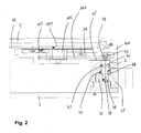
- the figure 2 is a partial and simplified cross-sectional view of a construction detail of the timepiece according to a preferred embodiment of the present invention, the section plane being different from that of the figure 1 ;
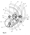
- the figure 3a is a simplified top view of a construction detail of the movement of the figure 1 in a first configuration
- the figure 3b is a top view similar to the view of the figure 3a in a second configuration
- the figure 3c is a top view similar to the view of the figure 3a in a third configuration.
- the figure 1 represents a simplified cross-sectional view of a timepiece 1 according to a preferred embodiment of the present invention.
- the timepiece 1 comprises a box comprising a middle part 2 delimited, on the one hand, by a bottom 3 and, on the other hand, by a rotating bezel 4 carrying an ice cream 5.
- the box contains a watch movement 6 of which some constituents are schematized on the figure 1 .
- the watch movement can be of the electromechanical or mechanical type. It is intended in particular to drive display members of the hour, including an hour hand 7, carried by an extension tube 8 integral with the barrel of the hour wheel 9, shown in this figure for illustrative purposes.
- the watch movement 6 is surmounted by an additional module 10 on the side of its plate 11, namely on the ice side.
- This additional module 10 includes a control mechanism which will be described in more detail below.
- the barrel extension tube of the hour wheel allows to cross the thickness of the additional module for driving the hour hand.
- the hour hand 7 evolves between a dial 12 and the ice 5, in a conventional manner.
- a time-setting rod 13 is provided for setting the time of the display members.
- the time setting rod is arranged in a plate hole and, fully disposed within the box, according to the features of the present invention.
- a first end 14 of the time setting rod is located in the region of the hour wheel, in a known manner, while its second end 15 is located between the periphery of the movement and the middle part 2, a sleeve 16, of square cross section, being screwed to this second end.
- a pinion 17 is mounted on the sleeve 16 by being free to slide, by a hole 18 formed in a cylindrical main portion 19, the latter being terminated by a disc 20 toothed and coaxial with the main portion.
- the hole 18 has a shape adapted so that the pinion 17 is integral in rotation with the sleeve 16.
- the disc 20 has a diameter such that its toothing 21 is located opposite the periphery of the additional module.
- the rotating bezel 4 is formed of two parts, not limited to, a lateral portion 400 and an upper portion 401 between which is screwed, by its outer periphery 22, a first ring 23, carrying a second ring 24 having a gearing oriented towards the outside. These elements are therefore all integral in rotation.
- the two parts of the bezel can in particular be assembled notch, or even by screwing.
- the first ring 23 has, from its outer periphery integral with the rotating bezel towards its inner periphery carrying the second ring 24, a first portion 25 extending substantially in a first plane parallel to the general plane of the middle part, a second portion 26 inclined towards the bottom of the timepiece and a third portion 27 extending substantially along a second plane parallel to the general plane of the middle part.
- the distance separating the first plane from the second plane is greater than the height separating the rotating bezel from the dial.
- the dial may have a radius greater than that of the inner edge of the upper part 401 of the rotating bezel to conceal all the elements other than those which are arranged above him.
- the toothing of the second ring 24 is arranged to be in permanent engagement with a mobile, or pinion, 28 rotatably mounted on the frame of the additional module.
- the configuration of the timepiece depicted on the figure 1 corresponds to its winding position.
- the toothing 21 of the pinion 17 is engaged with the pinion 28 to ensure the kinematic connection between the rotating bezel 4 and the time setting rod.
- any rotation of the rotating bezel is transmitted to the time setting rod via pinion 28.
- the time-setting rod carries a conventional-type sliding pinion 30 in the region of its first end 14. It is capable of moving along a square of the setting rod. hour, in the axial direction of the latter, between an initial position farther from the first end 14 and an hour-setting position close to this end 14.
- the movement comprises a lever cooperating with a throat annular sliding pinion by a stud, a portion is visible in section in this figure, to control its movements. This lever will be described in more detail in relation to Figures 3a to 3c .
- the sliding pinion 30 is intended to be arranged in engagement with a time-setting reference 31, in the time setting configuration, the return being itself disposed on the platen of the movement being in permanent engagement with the hour wheel 9. Therefore, rotations of the rotating bezel, in this configuration, are transmitted to the hour wheel, so the hour hand, to allow the adjustment of its position.
- the timepiece shown is of mechanical type, the time setting rod being also used to perform the winding of a mainspring (not shown).
- a winding pinion 32 is mounted free to rotate and translate on the rod 13.
- the winding pinion can be rotated in one direction by the sliding pinion, in a conventional manner, when the latter is in its winding position, corresponding to the position initial defined above.
- the winding pinion is arranged in permanent engagement with a crown wheel 33, connected to the barrel shaft (not visible).
- the timepiece according to the present invention thus preferably comprises three different configurations, preferably associated with three different positions of an external control member: a first neutral position, in which the rotations of the rotating bezel have no effect on the movement of the movement, a second winding position in which the rotations of the rotating bezel in a predefined direction can reload a mainspring, and a third time setting position in which the rotations of the rotating bezel in one direction or in the other allow to adjust the position of the display organs of the time.
- the external control member advantageously takes the form of a lever 35 cooperating with the control mechanism arranged in the additional module of the timepiece, which will be described in more detail. detail in relation to the Figures 3a to 3c .
- the figure 2 represents a cross-sectional view of the timepiece 1 according to a section plane different from that of the figure 1 highlighting the nature of the mechanical connection means used to transmit the movements of the external control lever to the control mechanism, located inside the box.
- the lever 35 has a fastening portion 36 inserted in a recess of the middle part and having a hole 37 of square section, the latter being traversed by a first end 38 of a connecting rod 39 defining a rotation shaft of the lever 35. compared to the middle part 2.
- the rod 39 has a section complementary to that of the hole 37 of the lever to ensure the rotational drive of the rod according to the movements of the lever. Furthermore, the rod is rotatably mounted in a hole 40 of the middle part whose wall has a generally cylindrical shape. The axial retention of the rod 39 in the hole of the middle part is guaranteed by a locking ring 41, held in abutment against the middle part by the lateral portion 400 of the rotating bezel 4 and disposed in the extension of the rod.
- annular groove 42 is formed in the central region of the rod of the link 39 to house an O-ring type seal 43, intended to be interposed under stress between the rod 39 and the wall of the hole 40 of the middle to ensure the tightness of the box.
- the connecting rod 39 has a second portion 44 of square section in the region of its second end located inside the box of the timepiece.
- This second portion 44 of the rod is integral with a first lever 45 of the control mechanism, so that the rotational movements of the external control lever 35 are retransmitted to the control mechanism, inside the box.
- the tightness of the box can be ensured reliably and efficiently.
- the arrangement of the means for making the sealed box is similar to that commonly used in watchmaking.
- the three possible positions of the external control lever are schematized for illustrative purposes on the figure 2 these positions corresponding to the three configurations of the timepiece mentioned above.
- the figures 3a , 3b and 3c represent simplified top views of a detail of the movement of the timepiece while the latter has, respectively, these first, second and third configurations.
- the figure 3a represents the timepiece when the external control lever is in its rest position, namely when it is arranged along the middle part.
- the box (not shown) comprises a housing in which the lever 35 is hidden when in its neutral position.
- the user in order to modify the configuration of the movement, in particular to wind it up or set the display members, the user must grasp the free end 50 of the control lever 35 and extract it from the housing while rotating the lever relative to the box.
- the first internal lever 45 integral with the connecting rod 39, comprises three successive portions 51, 52, 53, substantially rectilinear and connected two by two by two elbows 54 and 55.
- This lever 45 comprises a pin 56 disposed in the region of the first elbow 54 and extending in a direction substantially perpendicular to the general plane of the lever 45.
- this lever also comprises an opening 57 of oblong elbow shape extending on either side of the second elbow 55 of the lever, both on his second 52 and third 53 rectilinear portions.
- a second substantially rectilinear lever 60 is fixed to the frame of the module by a first 61 of its ends, being free to rotate relative to an axis X, while its second end 62 is located in the region of the third portion 53 of the first lever 45.
- the second end 62 of the second lever 60 is slaved to the oblong opening 57 of the first lever 45 by means of a bearing screw 63 secured to the second lever 60 and whose head is located on the opposite side to that of the first lever, with respect to the second lever.
- the ends of the second lever are disposed on either side of a plane P containing the axis of the time-setting rod and being perpendicular to the general plane of the second lever 60.
- the second lever 60 comprises a pin 64 extending, in a direction substantially perpendicular to the general plane of the lever, in the direction of the time-setting rod 13. More specifically, the latter has an annular groove 65 ( figure 1 ) inside which is engaged the free end of the pin 64.
- the control mechanism has a third 70 and a fourth 80 additional internal levers.
- the third lever 70 has two substantially rectilinear portions 71, 72 connected by a bend 73, in the region of which is provided a pivot axis 74 of the lever relative to the additional module.
- a substantially straight slot 75 is formed in the region of a first free end of the third lever, while its second free end carries a pin 76, similar to that of the first lever 45 and extending towards the bottom of the box.
- the third lever 70 is positioned in the additional module so that its pivot axis 74 and its second end are respectively disposed on either side of the plane P defined above. More precisely, the third internal lever 70 is arranged in such a way that the slot 75 of its first end cooperates with the pin 56 of the first lever 45.
- the fourth internal lever 80 has three substantially straight portions 81, 82, 83 connected two by two by two elbows 84, 85.
- a first portion 81, short, has a slot 86, open on a first free end of the lever and extending on the second portion 82 with an elbow.
- the fourth internal lever 80 is secured to the additional module by an axis of rotation 87 located in the region of the elbow 85 connecting the second 82 and third 83 portions of the lever.
- This elbow 85 being located in the immediate vicinity of the second lever 60, it has a cutout 88 allowing free movements of one of these levers relative to the other.
- the second free end of the fourth lever 80 is located between the middle part 2 and the lateral part 400 of the rotating bezel and carries a pin 89 extending in the direction of the pinion 17, to cooperate with an annular groove 90 (referenced on FIG. figure 1 ) of its principal portion 19.
- the control mechanism further comprises a pull lever 100, a first spout 101 of which is disposed in the groove 65 of the time-setting rod 13 and a second spout 102 of which is intended to act on an additional lever (not shown). ), in conventional manner, to move the sliding pinion 30 and activate or deactivate the time setting function.
- a curved spring 104 is also provided to allow the user to better sense the changes in movement pattern as he or she manipulates the external control lever, particularly between the neutral and intermediate positions.
- the curved spring 104 is fixed on the additional module by a base 105, while its free end 106 has a position and a shape adapted to cooperate with the pin 56 of the first internal lever 45.
- the free end of the curved spring presents two bearing surfaces 107 and 108, adjacent, associated with the first two configurations of the movement.
- FIGS. 3a to 3c represent a preferred embodiment of a movement according to the present invention comprising, in addition to what has just been described, a display mechanism of the position in which the external control lever 35 is at each moment.
- This display mechanism comprises a rake 110 whose end 111 not toothed is rotationally fixed to the connecting rod 39, and therefore the external control lever 35.
- the toothing of the rake 110 meshes with a pinion gear 112 mounted coaxially and rotationally fixed to a disc 113 indicating the position of the external control lever.
- the disc 113 thus bears the inscriptions 0, 1 and 2, for non-limiting indication, to indicate that the external control lever is, respectively, in its neutral position, in its intermediate position and in its position farthest from the middle, which corresponds as it will be exposed below to neutral positions, reassembly and time setting.
- a triangular window 114 cut in the dial 12 and through which the position indications are made visible to a user.
- the external control lever 35 is in neutral position or rest in the configuration of the figure 3a , which is indicated by the number 0 in 114 triangular window look. He is close to the middle. It can be seen that, in this position of the external control lever, the toothing 21 of the pinion 17 is not in engagement with the pinion 28. Consequently, a rotation of the rotating bezel causes the pinion 28 to rotate without causing rotation of the pinion. the time setting rod.
- the pin 56 acts on the slot 75 of the third internal lever 70 and causes the latter to pivot in the direction of counterclockwise rotation which then itself acts on the fourth internal lever 80 by the intermediate of its pin 76.
- the fourth lever is driven in a clockwise rotational movement, which leads to the application of traction by its pin 89 on the groove 90 of the pinion 17.
- the pinion is thus pulled towards the center of the movement, bringing its toothing 21 into engagement with the pinion 28.
- This position corresponds to that represented on the figure 1 , on which it appears that, when the rotating bezel 4 is actuated by the user, the time setting rod 13 is rotated to carry out the winding of the movement, by means of the winding pinion 32 and the crown wheel 33.
- control lever 35 When the control lever 35 is pulled from its intermediate position to its position 2, it is again rotated the first internal lever 45 in the clockwise direction to bring it into the position of the figure 3c .
- the first internal lever 45 is rotated and acts on the second lever 60, through its oblong opening 57, to rotate in the anticlockwise direction of rotation.
- the second internal lever 60 then acts in turn on the time setting rod, via its pin 64 and the pull rocker 100, to move it in its axial direction, outwardly.
- the sliding pinion 30 is moved, via the pull lever 100.
- the control mechanism is then arranged to allow a time setting of the timepiece by rotating the rotating bezel.
- the passage of the external control lever from position 0 to position 1 establishes a kinematic connection between the rotating bezel 4 and the time setting rod 13 to allow the reassembly of the movement, without moving the rod to the extent that it is connected, by default, to the winding means.
- the passage of the lever 35 from the position 1 to the position 2 causes the displacement of the time-setting rod 13 to disengage the winding means and actuate the sliding pinion 30, which makes it possible to connect the rod to the bodies of displaying the time and setting the time of the timepiece.
- the state of the kinematic link between the rotating bezel and the time setting rod is not affected during this second passage to allow a time setting by rotating the rotating bezel.
- the kinematic connection between the rotating bezel and the time-setting rod is permanent.
- two different positions of the external control lever 35 may be sufficient, namely a first position, reassembly, and a second position, setting time.
- the passage from one position to another of the lever would in particular enable or disable the connection between the time setting rod and the display members.
- an additional ring 115 is screwed into the bezel 4, this additional ring being in turn retained against the middle part 2 by the ring 41.
- the latter is, in fact, maintained in a predefined position, relative to the middle part, by feet 116 of which one is visible on the figure 1 .
- Each of these feet is secured to the middle part by means of a screw 117 whose head is accessible from the face of the caseband arranged facing the bottom 3.
- the bottom can be connected to the middle part by any suitable means, in particular by cooperation of a thread formed at its periphery with an internal thread of the middle part, by screws visible from the outside of the box, or by a notched connection.
- the axial retention of the connecting rod 39 by the ring 41 is achieved by means of a plug 120 ( figure 2 ) of which a first end is housed inside the square portion 44 of the connecting rod while its second end is placed in abutment against the ring 41.
Landscapes
- Physics & Mathematics (AREA)
- General Physics & Mathematics (AREA)
- Electric Clocks (AREA)
- Electromechanical Clocks (AREA)
Claims (10)
- Uhr (1), umfassend
ein Gehäuse (2, 3), das einen drehbaren Außenring trägt (4) und ein Uhrmacheruhrwerk enthält,
Mittel zur Anzeige der Uhrzeit (9, 7), und
einen Mechanismus zur Zeigerstellung, darunter eine Stellwelle (13), die vollständig in dem Gehäuse untergebracht ist und ausgebildet, um zwischen mindestens einer ersten axialen Zeigerstellung und einer zweiten axialen Zeigerstellung verschiebbar zu sein,
Verbindungsmittel (24, 28, 21, 17), die imstande sind, die Herstellung einer kinematischen Verbindung zwischen dem drehbaren Außenring und der Stellwelle zu erlauben, so dass eine Rotation des drehbaren Außenrings eine Rotation der Stellwelle bewirkt,
einen äußeren Steuerhebel (35), der drehbar auf dem Gehäuse montiert ist,
einen Steuermechanismus (45, 60, 70, 80), der ausgebildet ist, um auf die Stellwelle einzuwirken und sie von einer axialen Stellung in die andere zu verschieben als Antwort auf eine Aktion, die auf den Steuerhebel ausgeübt wurde und eine Verschiebung von einem Endabschnitt (50) des äußeren Steuerhebels zwischen einer Stellung und einer anderen bewirkt, um eine Betätigung des Mechanismus zur Zeigerstellung durch Rotation des drehbaren Außenrings zu erlauben,
dadurch gekennzeichnet, dass der Endabschnitt (50) des äußeren Steuerhebels ausgebildet ist, um zwischen mindestens einer ersten neutralen Stellung, in der die Rotationen des drehbaren, vom Uhrwerk entkoppelten Außenrings keine Auswirkung auf den Gang des Uhrwerks haben, und einer zweiten Zeigerstellstellung verschiebbar zu sein. - Uhr nach Anspruch 1, wobei das Gehäuse einen Mittelteil (2) umfasst, dadurch gekennzeichnet, dass der äußere Steuerhebel (35) rotierend mit einer Verbindungswelle (39) verbunden ist, die drehbar in dem Mittelteil montiert ist, indem sie etwa senkrecht zu einer allgemeinen Ebene desselben steht, wobei die Verbindungswelle im übrigen rotierend mit einem ersten inneren Hebel (45) des Steuermechanismus verbunden ist.
- Uhr nach Anspruch 1 oder 2, wobei das Gehäuse ein Uhrmacheruhrwerksgestell (10, 11) aufnimmt, dadurch gekennzeichnet, dass der Steuermechanismus einen zweiten inneren Hebel (60) umfasst, der drehbar um eine Achse X auf dem Gestell montiert ist und, indem er sich gemäß einer Querrichtung, in Bezug auf die Längsrichtung der Stellwelle (13) erstreckt, etwa gemäß einer allgemeinen Ebene, wobei der zweite innere Hebel eine Region (62) zur Aufnahme einer Kraft umfasst, die vom äußeren Steuerhebel (35) übertragen wird und eine Abstützfläche (64), die derart ausgebildet ist, dass sie mindestens indirekt mit der Stellwelle zusammenarbeitet, und
dass die Aufnahmeregion und die Achse X jeweils auf der einen und der anderen Seite einer Ebene P angeordnet sind, die die Stellwelle enthält und senkrecht zur allgemeinen Ebene des zweiten Hebels ist. - Uhr nach Anspruch 3, dadurch gekennzeichnet, dass der Steuermechanismus mindestens einen zusätzlichen inneren Hebel (100) umfasst, der ausgebildet ist, um einen von der Stellwelle (13) getragenen Kupplungstrieb (30) gleichzeitig mit den Verschiebungen der Stellwelle zwischen der einen und der anderen ihrer axialen Stellungen zu verschieben.
- Uhr nach einem der vorangehenden Ansprüche, dadurch gekennzeichnet, dass die Verbindungsmittel einen Trieb (17) umfassen, der rotierend mit der Stellwelle (13) verbunden ist und ausgebildet, um von dem Steuermechanismus verschiebbar zu sein, um eine mechanische Verbindung mit einem Drehteil (28) herzustellen, das kinematisch mit dem drehbaren Außenring (4) verbunden ist, ohne axiale Verschiebung der Stellwelle, als Antwort auf eine auf den Steuerhebel (35) ausgeübte Aktion, die eine Verschiebung des Endabschnitts (50) zwischen der ersten Stellung und einer Zwischen-Aufzugsstellung bewirkt, um die Herstellung der kinematischen Verbindung zwischen dem drehbaren Außenring und der Stellwelle zu erlauben.
- Uhr nach einem der vorangehenden Ansprüche, dadurch gekennzeichnet, dass die Verbindungsmittel einen Ring (23) umfassen, der rotierend mit dem drehbaren Außenring (4) verbunden ist und eine Zahnung (24) trägt, die ausgebildet ist, um mit einem Drehteil (28) zusammenzuarbeiten, das ausgebildet ist, damit die Stellwelle (13) rotierend durch Ineingriffnahme antreibbar ist.
- Uhr nach Anspruch 6, die ein Zifferblatt (12) umfasst, über dem sich mindestens ein Organ zur Anzeige der Zeit (7) bewegt, wobei der Mittelteil (2) auf seiner dem Zifferblatt gegenüberliegenden Seite durch einen Boden (3) verschlossen ist, dadurch gekennzeichnet, dass der Ring (23) im Querschnitt ab seinem äußeren Umfang (22), der mit dem drehbaren Außenring (4) verbunden ist, in Richtung seines inneren Umfangs, der die Zahnung (24) trägt, einen ersten Abschnitt (25) aufweist, der sich etwa gemäß einer ersten Ebene parallel zu einer allgemeinen Ebene des Mittelteils erstreckt, einen zweiten Abschnitt (26), der in Richtung des Bodens geneigt ist und einen dritten Abschnitt (27), der sich etwa gemäß einer zweiten Ebene parallel zur allgemeinen Ebene des Mittelteils erstreckt, wobei die Entfernung, die die erste Ebene von der zweiten Ebene trennt, größer ist als die Höhe, die den drehbaren Außenring vom Zifferblatt trennt.
- Uhr nach einem der vorangehenden Ansprüche, wenn sie von Anspruch 2 abhängen, dadurch gekennzeichnet, dass die Verbindungswelle (39) in einem Loch (40) des Mittelteils (2) gelagert ist, mit etwa zylindrischer Wand über mindestens einen Teil seiner Länge, und einen zylindrischen Abschnitt (42) aufweist mit einem Durchmesser, der kleiner ist als der Durchmesser des Lochs, wobei eine Dichtung (43) vom Typ O-Ring zwischen der Welle und der Wand zwischengestellt ist.
- Uhr nach einem der vorangehenden Ansprüche, wobei das Gehäuse von einem Glas (5) verschlossen ist, dadurch gekennzeichnet, dass das Glas von dem drehbaren Außenring (4) getragen wird.
- Uhr nach einem der Ansprüche 2, 3 bis 9, wenn sie von Anspruch 2 abhängen, dadurch gekennzeichnet, dass sie weiterhin Mittel (110, 112) zum Steuern der Mittel (113) zur Anzeige der Stellung umfasst, in der sich der äußere Steuerhebel (35) befindet, wobei die Steuermittel eine kinematische Verbindung mit der Verbindungswelle (39) aufweisen.
Applications Claiming Priority (2)
| Application Number | Priority Date | Filing Date | Title |
|---|---|---|---|
| CH5032006 | 2006-03-29 | ||
| PCT/EP2007/052740 WO2007110362A2 (fr) | 2006-03-29 | 2007-03-22 | Piece d'horlogerie comportant un mecanisme de mise a l'heure commande par une lunette tournante |
Publications (2)
| Publication Number | Publication Date |
|---|---|
| EP2010972A2 EP2010972A2 (de) | 2009-01-07 |
| EP2010972B1 true EP2010972B1 (de) | 2010-06-30 |
Family
ID=38519597
Family Applications (1)
| Application Number | Title | Priority Date | Filing Date |
|---|---|---|---|
| EP07727216A Not-in-force EP2010972B1 (de) | 2006-03-29 | 2007-03-22 | Uhr mit einem durch einen drehbaren aussenring gesteurten zeigereinstellmechanismus |
Country Status (4)
| Country | Link |
|---|---|
| US (1) | US20110141859A1 (de) |
| EP (1) | EP2010972B1 (de) |
| AT (1) | ATE472755T1 (de) |
| WO (1) | WO2007110362A2 (de) |
Families Citing this family (3)
| Publication number | Priority date | Publication date | Assignee | Title |
|---|---|---|---|---|
| CH708755A1 (de) * | 2013-10-30 | 2015-04-30 | Richemont Int Sa | Halte- und Indexierungsvorrichtung für Uhren. |
| CH710302A2 (it) * | 2014-10-21 | 2016-04-29 | Tcm S R L | Dispostivo di regolazione delle funzioni di un orologio. |
| EP3647885B1 (de) * | 2018-11-02 | 2026-01-07 | Tissot S.A. | Steuerungsverfahren des stromverbrauchs einer armbanduhr |
Family Cites Families (11)
| Publication number | Priority date | Publication date | Assignee | Title |
|---|---|---|---|---|
| US812963A (en) * | 1905-05-24 | 1906-02-20 | Charles Rode Stucky | Stem-winding mechanism for timepieces. |
| US1226402A (en) * | 1916-05-12 | 1917-05-15 | Waterbury Clock Co | Keyless clock. |
| US1493466A (en) * | 1922-06-06 | 1924-05-13 | Burnstine Abraham | Second-hand-setting mechanism for watches |
| CH137801A (fr) * | 1929-02-26 | 1930-01-31 | Cornioley Francis | Remontoir pour pièce d'horlogerie. |
| FR1203133A (fr) * | 1958-07-22 | 1960-01-15 | Montre-bracelet à sonnerie d'avertissement | |
| US5742565A (en) * | 1996-05-21 | 1998-04-21 | Timex Corporation | Crown setting device for a timepiece |
| US6379037B1 (en) * | 2000-03-15 | 2002-04-30 | Timex Group B.V. | Setting mechanism for a timepiece |
| EP1152303B1 (de) * | 2000-05-05 | 2006-07-19 | Rolex Sa | Uhr mit Aufzugsmechanismus und mit Korrekturmechanismus für mindestens zwei anzeigende Organe |
| EP1584000B1 (de) * | 2002-12-06 | 2009-07-15 | Powermike.com LP | Weltzeituhr |
| JP4849986B2 (ja) * | 2006-07-25 | 2012-01-11 | セイコーインスツル株式会社 | 携帯時計 |
| EP1939699B1 (de) * | 2006-12-29 | 2012-05-30 | Montres Breguet S.A. | Multifunktionsvorrichtung zur koaxialen Korrektur |
-
2007
- 2007-03-22 US US12/294,948 patent/US20110141859A1/en not_active Abandoned
- 2007-03-22 WO PCT/EP2007/052740 patent/WO2007110362A2/fr not_active Ceased
- 2007-03-22 AT AT07727216T patent/ATE472755T1/de not_active IP Right Cessation
- 2007-03-22 EP EP07727216A patent/EP2010972B1/de not_active Not-in-force
Also Published As
| Publication number | Publication date |
|---|---|
| WO2007110362A2 (fr) | 2007-10-04 |
| EP2010972A2 (de) | 2009-01-07 |
| US20110141859A1 (en) | 2011-06-16 |
| ATE472755T1 (de) | 2010-07-15 |
| WO2007110362A3 (fr) | 2007-12-06 |
Similar Documents
| Publication | Publication Date | Title |
|---|---|---|
| EP2984526B1 (de) | Vorrichtung zur auswahl und betätigung der funktionen eines uhrwerks | |
| EP2365407B1 (de) | Vorrichtung zum Aufziehen und zur Zeiteinstellung für ein Uhrwerk | |
| EP3407144A2 (de) | Uhr, die eine verriegelungsvorrichtung für eine drucktaste umfasst | |
| EP1513030A1 (de) | Uhr mit zwei relativ zueinander drehenden Uhrgehäusen | |
| WO2011104480A1 (fr) | Couronne de remontoir de montre multifonctions | |
| EP1748330B1 (de) | Vorrichtung mit Spindel zum Aufziehen und zur Zeiteinstellung von Uhren | |
| EP2238519B1 (de) | Uhr mit chronographie-mechanismus | |
| EP1728128B1 (de) | Uhr mit zwei drehbaren kronen | |
| EP2010972B1 (de) | Uhr mit einem durch einen drehbaren aussenring gesteurten zeigereinstellmechanismus | |
| CH700843A1 (fr) | Organe de commande pour piece d'horlogerie. | |
| EP2639656A1 (de) | Vorrichtung zur Betätigung einer Taucheruhr | |
| EP1708052B1 (de) | Uhrwerk | |
| EP1722282B1 (de) | Vorrichtung zur Einstellung der axialen Position einer Krone für Uhren | |
| EP2477080B1 (de) | Uhr mit Zeitzonenanzeige entsprechend einer ausgewählten Uhrzeit | |
| EP1960848B1 (de) | Hammer einer uhr | |
| EP1513031B1 (de) | Uhr mit zwei relativ zueinander drehenden Uhrgehäusen | |
| EP4336275A1 (de) | Gehäuse für eine uhr mit einer externen drehbaren lunette zur steuerung eines internen anzeigemobils | |
| EP1791038A1 (de) | Uhrwerk | |
| CH720021A2 (fr) | Boite pour pièce d'horlogerie comportant une lunette tournante externe commandant un mobile d'affichage interne. | |
| CH720894B1 (fr) | Mécanisme horloger comprenant une came | |
| EP1288743A1 (de) | Kupplungsvorrichtung für eine Uhr | |
| CH702802B1 (fr) | Dispositif de commande de remontage et de mise à l'heure pour un mouvement d'horlogerie. | |
| CH720984B1 (fr) | Mécanisme de commande pour pièce d'horlogerie | |
| FR2492999A1 (fr) | Dispositif mecanique de mise a l'heure d'une montre a affichage analogique | |
| WO2026052807A1 (fr) | Dispositif de commande pour piece d'horlogerie, destine a actionner au moins deux fonctions de la piece d'horlogerie |
Legal Events
| Date | Code | Title | Description |
|---|---|---|---|
| PUAI | Public reference made under article 153(3) epc to a published international application that has entered the european phase |
Free format text: ORIGINAL CODE: 0009012 |
|
| 17P | Request for examination filed |
Effective date: 20081021 |
|
| AK | Designated contracting states |
Kind code of ref document: A2 Designated state(s): AT BE BG CH CY CZ DE DK EE ES FI FR GB GR HU IE IS IT LI LT LU LV MC MT NL PL PT RO SE SI SK TR |
|
| AX | Request for extension of the european patent |
Extension state: AL BA HR MK RS |
|
| RAP1 | Party data changed (applicant data changed or rights of an application transferred) |
Owner name: GIULIANO MAZZUOLI S.R.L. |
|
| GRAP | Despatch of communication of intention to grant a patent |
Free format text: ORIGINAL CODE: EPIDOSNIGR1 |
|
| DAX | Request for extension of the european patent (deleted) | ||
| GRAS | Grant fee paid |
Free format text: ORIGINAL CODE: EPIDOSNIGR3 |
|
| GRAA | (expected) grant |
Free format text: ORIGINAL CODE: 0009210 |
|
| AK | Designated contracting states |
Kind code of ref document: B1 Designated state(s): AT BE BG CH CY CZ DE DK EE ES FI FR GB GR HU IE IS IT LI LT LU LV MC MT NL PL PT RO SE SI SK TR |
|
| REG | Reference to a national code |
Ref country code: GB Ref legal event code: FG4D Free format text: NOT ENGLISH Ref country code: CH Ref legal event code: EP |
|
| REG | Reference to a national code |
Ref country code: IE Ref legal event code: FG4D Free format text: LANGUAGE OF EP DOCUMENT: FRENCH |
|
| REF | Corresponds to: |
Ref document number: 602007007463 Country of ref document: DE Date of ref document: 20100812 Kind code of ref document: P |
|
| REG | Reference to a national code |
Ref country code: NL Ref legal event code: VDEP Effective date: 20100630 |
|
| PG25 | Lapsed in a contracting state [announced via postgrant information from national office to epo] |
Ref country code: LT Free format text: LAPSE BECAUSE OF FAILURE TO SUBMIT A TRANSLATION OF THE DESCRIPTION OR TO PAY THE FEE WITHIN THE PRESCRIBED TIME-LIMIT Effective date: 20100630 Ref country code: SE Free format text: LAPSE BECAUSE OF FAILURE TO SUBMIT A TRANSLATION OF THE DESCRIPTION OR TO PAY THE FEE WITHIN THE PRESCRIBED TIME-LIMIT Effective date: 20100630 |
|
| LTIE | Lt: invalidation of european patent or patent extension |
Effective date: 20100630 |
|
| PG25 | Lapsed in a contracting state [announced via postgrant information from national office to epo] |
Ref country code: LV Free format text: LAPSE BECAUSE OF FAILURE TO SUBMIT A TRANSLATION OF THE DESCRIPTION OR TO PAY THE FEE WITHIN THE PRESCRIBED TIME-LIMIT Effective date: 20100630 Ref country code: FI Free format text: LAPSE BECAUSE OF FAILURE TO SUBMIT A TRANSLATION OF THE DESCRIPTION OR TO PAY THE FEE WITHIN THE PRESCRIBED TIME-LIMIT Effective date: 20100630 Ref country code: SI Free format text: LAPSE BECAUSE OF FAILURE TO SUBMIT A TRANSLATION OF THE DESCRIPTION OR TO PAY THE FEE WITHIN THE PRESCRIBED TIME-LIMIT Effective date: 20100630 Ref country code: AT Free format text: LAPSE BECAUSE OF FAILURE TO SUBMIT A TRANSLATION OF THE DESCRIPTION OR TO PAY THE FEE WITHIN THE PRESCRIBED TIME-LIMIT Effective date: 20100630 |
|
| PG25 | Lapsed in a contracting state [announced via postgrant information from national office to epo] |
Ref country code: PL Free format text: LAPSE BECAUSE OF FAILURE TO SUBMIT A TRANSLATION OF THE DESCRIPTION OR TO PAY THE FEE WITHIN THE PRESCRIBED TIME-LIMIT Effective date: 20100630 |
|
| PG25 | Lapsed in a contracting state [announced via postgrant information from national office to epo] |
Ref country code: EE Free format text: LAPSE BECAUSE OF FAILURE TO SUBMIT A TRANSLATION OF THE DESCRIPTION OR TO PAY THE FEE WITHIN THE PRESCRIBED TIME-LIMIT Effective date: 20100630 Ref country code: NL Free format text: LAPSE BECAUSE OF FAILURE TO SUBMIT A TRANSLATION OF THE DESCRIPTION OR TO PAY THE FEE WITHIN THE PRESCRIBED TIME-LIMIT Effective date: 20100630 |
|
| REG | Reference to a national code |
Ref country code: IE Ref legal event code: FD4D |
|
| PG25 | Lapsed in a contracting state [announced via postgrant information from national office to epo] |
Ref country code: CZ Free format text: LAPSE BECAUSE OF FAILURE TO SUBMIT A TRANSLATION OF THE DESCRIPTION OR TO PAY THE FEE WITHIN THE PRESCRIBED TIME-LIMIT Effective date: 20100630 Ref country code: IS Free format text: LAPSE BECAUSE OF FAILURE TO SUBMIT A TRANSLATION OF THE DESCRIPTION OR TO PAY THE FEE WITHIN THE PRESCRIBED TIME-LIMIT Effective date: 20101030 Ref country code: CY Free format text: LAPSE BECAUSE OF FAILURE TO SUBMIT A TRANSLATION OF THE DESCRIPTION OR TO PAY THE FEE WITHIN THE PRESCRIBED TIME-LIMIT Effective date: 20100630 Ref country code: RO Free format text: LAPSE BECAUSE OF FAILURE TO SUBMIT A TRANSLATION OF THE DESCRIPTION OR TO PAY THE FEE WITHIN THE PRESCRIBED TIME-LIMIT Effective date: 20100630 Ref country code: PT Free format text: LAPSE BECAUSE OF FAILURE TO SUBMIT A TRANSLATION OF THE DESCRIPTION OR TO PAY THE FEE WITHIN THE PRESCRIBED TIME-LIMIT Effective date: 20101102 Ref country code: SK Free format text: LAPSE BECAUSE OF FAILURE TO SUBMIT A TRANSLATION OF THE DESCRIPTION OR TO PAY THE FEE WITHIN THE PRESCRIBED TIME-LIMIT Effective date: 20100630 |
|
| PG25 | Lapsed in a contracting state [announced via postgrant information from national office to epo] |
Ref country code: IT Free format text: LAPSE BECAUSE OF FAILURE TO SUBMIT A TRANSLATION OF THE DESCRIPTION OR TO PAY THE FEE WITHIN THE PRESCRIBED TIME-LIMIT Effective date: 20100630 |
|
| PG25 | Lapsed in a contracting state [announced via postgrant information from national office to epo] |
Ref country code: IE Free format text: LAPSE BECAUSE OF FAILURE TO SUBMIT A TRANSLATION OF THE DESCRIPTION OR TO PAY THE FEE WITHIN THE PRESCRIBED TIME-LIMIT Effective date: 20100630 Ref country code: DK Free format text: LAPSE BECAUSE OF FAILURE TO SUBMIT A TRANSLATION OF THE DESCRIPTION OR TO PAY THE FEE WITHIN THE PRESCRIBED TIME-LIMIT Effective date: 20100630 |
|
| PLBE | No opposition filed within time limit |
Free format text: ORIGINAL CODE: 0009261 |
|
| STAA | Information on the status of an ep patent application or granted ep patent |
Free format text: STATUS: NO OPPOSITION FILED WITHIN TIME LIMIT |
|
| PG25 | Lapsed in a contracting state [announced via postgrant information from national office to epo] |
Ref country code: GR Free format text: LAPSE BECAUSE OF FAILURE TO SUBMIT A TRANSLATION OF THE DESCRIPTION OR TO PAY THE FEE WITHIN THE PRESCRIBED TIME-LIMIT Effective date: 20101001 |
|
| 26N | No opposition filed |
Effective date: 20110331 |
|
| PG25 | Lapsed in a contracting state [announced via postgrant information from national office to epo] |
Ref country code: ES Free format text: LAPSE BECAUSE OF FAILURE TO SUBMIT A TRANSLATION OF THE DESCRIPTION OR TO PAY THE FEE WITHIN THE PRESCRIBED TIME-LIMIT Effective date: 20101011 |
|
| REG | Reference to a national code |
Ref country code: DE Ref legal event code: R097 Ref document number: 602007007463 Country of ref document: DE Effective date: 20110330 |
|
| BERE | Be: lapsed |
Owner name: GIULIANO MAZZUOLI S.R.L. Effective date: 20110331 |
|
| PG25 | Lapsed in a contracting state [announced via postgrant information from national office to epo] |
Ref country code: MC Free format text: LAPSE BECAUSE OF NON-PAYMENT OF DUE FEES Effective date: 20110331 |
|
| REG | Reference to a national code |
Ref country code: CH Ref legal event code: PL |
|
| GBPC | Gb: european patent ceased through non-payment of renewal fee |
Effective date: 20110322 |
|
| REG | Reference to a national code |
Ref country code: FR Ref legal event code: ST Effective date: 20111130 |
|
| PG25 | Lapsed in a contracting state [announced via postgrant information from national office to epo] |
Ref country code: BE Free format text: LAPSE BECAUSE OF NON-PAYMENT OF DUE FEES Effective date: 20110331 Ref country code: MT Free format text: LAPSE BECAUSE OF FAILURE TO SUBMIT A TRANSLATION OF THE DESCRIPTION OR TO PAY THE FEE WITHIN THE PRESCRIBED TIME-LIMIT Effective date: 20100630 |
|
| PG25 | Lapsed in a contracting state [announced via postgrant information from national office to epo] |
Ref country code: CH Free format text: LAPSE BECAUSE OF NON-PAYMENT OF DUE FEES Effective date: 20110331 Ref country code: DE Free format text: LAPSE BECAUSE OF NON-PAYMENT OF DUE FEES Effective date: 20111001 Ref country code: LI Free format text: LAPSE BECAUSE OF NON-PAYMENT OF DUE FEES Effective date: 20110331 Ref country code: FR Free format text: LAPSE BECAUSE OF NON-PAYMENT OF DUE FEES Effective date: 20110331 |
|
| REG | Reference to a national code |
Ref country code: DE Ref legal event code: R119 Ref document number: 602007007463 Country of ref document: DE Effective date: 20111001 |
|
| PG25 | Lapsed in a contracting state [announced via postgrant information from national office to epo] |
Ref country code: GB Free format text: LAPSE BECAUSE OF NON-PAYMENT OF DUE FEES Effective date: 20110322 |
|
| PG25 | Lapsed in a contracting state [announced via postgrant information from national office to epo] |
Ref country code: LU Free format text: LAPSE BECAUSE OF NON-PAYMENT OF DUE FEES Effective date: 20110322 |
|
| PG25 | Lapsed in a contracting state [announced via postgrant information from national office to epo] |
Ref country code: BG Free format text: LAPSE BECAUSE OF FAILURE TO SUBMIT A TRANSLATION OF THE DESCRIPTION OR TO PAY THE FEE WITHIN THE PRESCRIBED TIME-LIMIT Effective date: 20100930 Ref country code: TR Free format text: LAPSE BECAUSE OF FAILURE TO SUBMIT A TRANSLATION OF THE DESCRIPTION OR TO PAY THE FEE WITHIN THE PRESCRIBED TIME-LIMIT Effective date: 20100630 |
|
| PG25 | Lapsed in a contracting state [announced via postgrant information from national office to epo] |
Ref country code: HU Free format text: LAPSE BECAUSE OF FAILURE TO SUBMIT A TRANSLATION OF THE DESCRIPTION OR TO PAY THE FEE WITHIN THE PRESCRIBED TIME-LIMIT Effective date: 20100630 |