EP1512937A2 - Vorrichtung zur Erfassung der Position eines ersten Fahrzeugteils in Bezug auf ein zweites Fahrzeugteil, insbesondere zur Bestimmung der Nickposition eines Fahrzeuges und Fahrzeug mit einer derartigen Vorrichtung - Google Patents
Vorrichtung zur Erfassung der Position eines ersten Fahrzeugteils in Bezug auf ein zweites Fahrzeugteil, insbesondere zur Bestimmung der Nickposition eines Fahrzeuges und Fahrzeug mit einer derartigen Vorrichtung Download PDFInfo
- Publication number
- EP1512937A2 EP1512937A2 EP04021163A EP04021163A EP1512937A2 EP 1512937 A2 EP1512937 A2 EP 1512937A2 EP 04021163 A EP04021163 A EP 04021163A EP 04021163 A EP04021163 A EP 04021163A EP 1512937 A2 EP1512937 A2 EP 1512937A2
- Authority
- EP
- European Patent Office
- Prior art keywords
- vehicle
- determining
- oscillator
- sensor inductance
- circuit
- Prior art date
- Legal status (The legal status is an assumption and is not a legal conclusion. Google has not performed a legal analysis and makes no representation as to the accuracy of the status listed.)
- Granted
Links
Images

Classifications
-
- G—PHYSICS
- G01—MEASURING; TESTING
- G01B—MEASURING LENGTH, THICKNESS OR SIMILAR LINEAR DIMENSIONS; MEASURING ANGLES; MEASURING AREAS; MEASURING IRREGULARITIES OF SURFACES OR CONTOURS
- G01B7/00—Measuring arrangements characterised by the use of electric or magnetic techniques
- G01B7/14—Measuring arrangements characterised by the use of electric or magnetic techniques for measuring distance or clearance between spaced objects or spaced apertures
-
- B—PERFORMING OPERATIONS; TRANSPORTING
- B60—VEHICLES IN GENERAL
- B60Q—ARRANGEMENT OF SIGNALLING OR LIGHTING DEVICES, THE MOUNTING OR SUPPORTING THEREOF OR CIRCUITS THEREFOR, FOR VEHICLES IN GENERAL
- B60Q1/00—Arrangement of optical signalling or lighting devices, the mounting or supporting thereof or circuits therefor
- B60Q1/02—Arrangement of optical signalling or lighting devices, the mounting or supporting thereof or circuits therefor the devices being primarily intended to illuminate the way ahead or to illuminate other areas of way or environments
- B60Q1/04—Arrangement of optical signalling or lighting devices, the mounting or supporting thereof or circuits therefor the devices being primarily intended to illuminate the way ahead or to illuminate other areas of way or environments the devices being headlights
- B60Q1/06—Arrangement of optical signalling or lighting devices, the mounting or supporting thereof or circuits therefor the devices being primarily intended to illuminate the way ahead or to illuminate other areas of way or environments the devices being headlights adjustable, e.g. remotely-controlled from inside vehicle
- B60Q1/08—Arrangement of optical signalling or lighting devices, the mounting or supporting thereof or circuits therefor the devices being primarily intended to illuminate the way ahead or to illuminate other areas of way or environments the devices being headlights adjustable, e.g. remotely-controlled from inside vehicle automatically
- B60Q1/10—Arrangement of optical signalling or lighting devices, the mounting or supporting thereof or circuits therefor the devices being primarily intended to illuminate the way ahead or to illuminate other areas of way or environments the devices being headlights adjustable, e.g. remotely-controlled from inside vehicle automatically due to vehicle inclination, e.g. due to load distribution
- B60Q1/115—Arrangement of optical signalling or lighting devices, the mounting or supporting thereof or circuits therefor the devices being primarily intended to illuminate the way ahead or to illuminate other areas of way or environments the devices being headlights adjustable, e.g. remotely-controlled from inside vehicle automatically due to vehicle inclination, e.g. due to load distribution by electric means
-
- B—PERFORMING OPERATIONS; TRANSPORTING
- B60—VEHICLES IN GENERAL
- B60G—VEHICLE SUSPENSION ARRANGEMENTS
- B60G2401/00—Indexing codes relating to the type of sensors based on the principle of their operation
- B60G2401/25—Capacitance type, e.g. as level indicator
-
- B—PERFORMING OPERATIONS; TRANSPORTING
- B60—VEHICLES IN GENERAL
- B60Q—ARRANGEMENT OF SIGNALLING OR LIGHTING DEVICES, THE MOUNTING OR SUPPORTING THEREOF OR CIRCUITS THEREFOR, FOR VEHICLES IN GENERAL
- B60Q2300/00—Indexing codes for automatically adjustable headlamps or automatically dimmable headlamps
- B60Q2300/10—Indexing codes relating to particular vehicle conditions
- B60Q2300/13—Attitude of the vehicle body
- B60Q2300/132—Pitch
Definitions
- the invention relates to a device for detecting the position of a first Vehicle part with respect to a second vehicle part, in particular for Determining the pitching position of a vehicle for the regulation of Lighting range of the vehicle headlights and a vehicle with a device to regulate the beam range of the vehicle headlights and a device for determining the pitch position of the vehicle.
- the range of the headlights of a vehicle is the inclination of the vehicle with respect to the surface of the terrain dependent, which is referred to as pitching position of the vehicle.
- the pitch position the vehicle changes when accelerating and decelerating and on the other hand when loading the vehicle.
- To determine the pitch position of a vehicle devices which have a device for Detecting the position of a stationary vehicle part with respect to a movable Capture vehicle part.
- the position of the control arm in relation captured on the vehicle chassis.
- the known devices for determining the Nick position via one or more rotary potentiometers (HALL potentiometer).
- the wishbone exerts a relative to the chassis extensive linear motion.
- the disadvantage is that the position detection of Wishbone with a rotary potentiometer that is not a linear motion, but a rotational movement, a relatively complex mechanical Coupling required.
- the mechanical coupling has in practice proved to be relatively susceptible to interference. In particular, problems arise in Pollution and icing.
- the known devices for determining the pitch position make in General of several rotary potentiometers use, with which the Position one of the two front and rear control arms of the vehicle in is determined with respect to the chassis. From the position of each control arm with respect to the chassis then the pitch of the vehicle in one Control unit detects the servomotors to adjust the position of the Headlight is on. Because several rotary potentiometer with the relative consuming mechanical coupling are used, takes the entire design effort and the susceptibility to even.
- DE 38 39 427 C2 describes a device for automatic control the headlight range of the headlights of motor vehicles passing over Differential variometer, which are arranged on the axles of the vehicle.
- Differential variometer which are arranged on the axles of the vehicle.
- Inductance of the variometer used to adjust the beam range of the headlights is used.
- the disadvantage is that the differential variables are relatively expensive of production.
- the invention has for its object to provide a device for detecting the Position of a first part with respect to a second part, which with relatively low circuit complexity works trouble-free.
- the invention has the object, a reliable To create working device that without high design effort Determining the pitching position of a vehicle allowed.
- Another task of Invention is to provide a vehicle in which the beam range of Vehicle headlights without major design effort in trouble-free Depending on the pitch position is regulated.
- the inductive measuring system has a Sensor inductance, which is to be arranged on one of the two vehicle parts. There The inductive measuring system works without contact, is a mechanical Coupling not required. As a result, the design effort is low. Also, there are no problems with pollution and icing.
- the inductive measuring system is a measuring system in which the Sensor inductance is part of an electrical resonant circuit, its quality (Attenuation) by the measuring distance x between the sensor inductance and a metallic object (target) is determined. For signal evaluation, the Amplitude change of the electrical oscillation of the resonant circuit in Used depending on the target distance.
- the target consists of a flat metal surface.
- ferromagnetic materials e.g. Plastics, organic materials or most liquids affect the quality (damping) of the resonant circuit not. Therefore, these materials or liquids are not recognized. If the respective vehicle part as such should not be metallic, may The vehicle part and a metal part are attached.
- a sensor inductance is not to understand that the position detecting device only a single Having sensor inductance. Rather, the position detection device also have multiple sensor inductances. In the simplest Embodiment, the position detecting device only a single Sensor inductance, with the relative movement of only two Vehicle parts is detected. Higher measurement accuracy is then achieved, if the position detection device has a plurality of sensor inductances.
- the position detection device has a freely oscillating oscillator, having a resonant circuit containing the sensor inductance.
- the resonant circuit is a parallel circuit of the Sensor inductance and a capacity.
- the resonant circuit can also be a Series connection of inductance and capacitance.
- the sensor inductance is preferably a toroidal coil which is semi-open Shell core is arranged. But there are also other designs possible.
- the Ring coil in the half-open pot core is the maximum measuring distance given that the target is no longer within the sphere of influence of the Shell core surface is exiting magnetic field lines.
- the toroidal coil in the half-open pot core allows detection of the target even if the measuring distance is relatively large.
- the sensitivity by choosing a particularly suitable Ferrite material can still be increased.
- the freely oscillating oscillator has means for damping the Oscillating circuit and means for excitation of the resonant circuit.
- the means for Damping of the resonant circuit have an amplifier, wherein the Resonant circuit is connected in the negative feedback of the amplifier, while the Means for exciting the resonant circuit between the output and Input of the amplifier have switched feedback branch, the means for generating a square-wave voltage signal from a Contains alternating voltage signal.
- the oscillator is a self-starting and self-oscillating system. This will allow the oscillation of the electrical oscillation always takes place at resonant frequency.
- the AC supply of the Sensor inductance corresponds to the function of a real power source. Thereby can be achieved on the one hand that the electrical oscillation at the Sensor inductance even at maximum occurring attenuation - accordingly minimum measuring path - permanently available. Because the vibration itself at maximum damping is still maintained, it is in the oscillatory system around a non-breaking oscillator.
- the measurement signal as an alternating voltage signal can be very high on the resonant circuit be tapped. This will provide an electrical separation of the feed and the signal tap on the same terminals of the sensor inductance reached. The feed can thus via a power source and the tap over a voltage measurement done.
- the current injection into the sensor inductance is achieved in that the LC parallel resonant circuit, which is in the negative feedback of the amplifier, of the square-wave voltage signal generated from the AC signal is, is driven. Because the square wave signal is a constant Amplitude is, the current in the resonant circuit is constant.
- the means for generating the square-wave voltage signal from the AC signal a pulse shaper and a driver, which are connected in series.
- Another particularly preferred embodiment provides an evaluation circuit before, from the generated from the oscillator AC signal with the Nick position of the vehicle correlated electrical measurement signal generated.
- the Evaluation circuit preferably has means for rectifying the AC signal on. If the recovered DC measurement voltage is temperature dependent and is not linear over the measuring path, the Evaluation circuit means for linearization and / or temperature compensation which preferably comprise a microcontroller. With the Microcontrollers can be used for linearization and temperature compensation necessary operations are easily realized.
- the measurement signal is preferably provided via an interface.
- the Evaluation circuit is also an encoding of the output signal in the form of digital modulation method, for example PCM (Pulse Code Modulation), in particular PWM (Pulse Width Modulation) possible.
- PCM Pulse Code Modulation
- PWM Pulse Width Modulation
- It is also one Data transmission via suitable bus systems, for example CAN (Controller Area Network) and LIN (Local Interconnection Network), but also LAN (Local Area Network) or other networks.
- CAN Controller Area Network
- LIN Local Interconnection Network
- LAN Local Area Network
- the vehicle according to the invention with a device for regulating the Lighting range of the vehicle headlights as a function of the pitch position of the Vehicle has the inventive device for determining the Nick position.
- the sensor inductance is preferably at one with respect to the horizontal plane of the vehicle as a reference plane fixed vehicle part arranged, with the distance to one opposite the reference plane movable vehicle part is measured, which is a metal part.
- a preferred embodiment provides that the movable vehicle part a the sensor inductance of opposite wishbone of the vehicle is.
- the Sensor inductance is preferably arranged on the vehicle chassis.
- the Distance measurement leads in practice to sufficiently accurate measurement results, since the relative movement of the control arm and chassis are low. Although the Transverse arm exerts a tilting movement, the tilting movement due to the small tilt angle with sufficient accuracy by a linear movement be approximated.
- the senor inductance on a to arrange relative to the reference plane movable vehicle part, wherein the stationary vehicle part is metallic.
- the oscillator circuit for non-contact determination of the Distance only in connection with a device for determining the Nick position of a vehicle is described, the oscillator circuit is also called those of independent inventive significance.
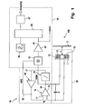
- the device 100 for determining the pitching position of a vehicle comprises an oscillator 10 with a resonant circuit 30 and an evaluation circuit 50th
- FIG. 1 shows a simplified block diagram of oscillator 10 and Evaluation circuit 50.
- a detailed block diagram of the oscillator 10 shows FIG. 2.
- the oscillator has a sensor inductance L and a capacitance C (Capacitor), which are connected in parallel. Sensor inductance and capacitance form the LC parallel resonant circuit 30.
- the sensor inductance L is from a Ring coil 11 formed in a semi-open shell core 12 made of ferrite material is arranged. The distance between the shell core surface 13 at the open side of the shell core 12 and the metallic body (target T) is with x denotes.
- the oscillator 10 has an amplifier 14 on.
- the amplifier 14 comprises an operational amplifier 15 with a first and second input 16, 17 and an output 18 ( Figure 2).
- the LC parallel resonant circuit 30 is parallel to the first input 16 and output 18 of the Operational amplifier 15 switched.
- About a resistor R1 is the Supply voltage VA at the second input 17 of the operational amplifier 15 on.
- the oscillator 10 has a Feedback branch 21, which has a pulse shaper 19, an inverting Driver 20 and a capacitor C 1, which are connected in series.
- the Feedback branch 21 connects the output 18 of the operational amplifier 15 via a resistor R0 to the first input 16 of the operational amplifier 15th
- the pulse shaper 19 generates from the sinusoidal AC voltage VSIN, the the LC parallel resonant circuit 30 and output 18 of the operational amplifier 15th is applied, an approximately rectangular signal from which the inverting driver 20 produces an exact square wave signal VRE which comprises the LC parallel resonant circuit 30, which is in the negative feedback of the amplifier 14, via the resistor R0 controls. Since the square wave signal VRE has a constant amplitude, is also the Current in the resonant circuit constant. The amplitude of the sinusoidal AC voltage VSIN at the output of the operational amplifier 15 can directly be set via R0.
- the pulse shaper 19 has an operational amplifier 22 with a first and second input 23, 24 and an output 25.
- a negative feedback branch 26, which includes a negative feedback circuit 27, connects the output 25 of the Operational amplifier 22 with its first input 23.
- Die Negative feedback circuit 27 serves to increase the rise time of the pulse shaper so limit that annoying overshoot and unnecessarily steep signal edges be avoided. Due to the "over-all" counter-coupling of the circuit the oscillation frequency always corresponds to that of the LC combination of the Resonant circuit predetermined resonant frequency.
- the reinforcing properties of the pulse shaper are designed so that at maximum attenuation of the Oscillating circuit occurring, minimal signal amplitudes of the oscillation signal VSIN can still be sufficiently recognized and strengthened. This will be ensures that the oscillation of the oscillator does not break off.
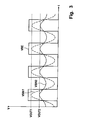
- Figure 3 shows the waveforms for VRE and VSIN for a first and a second distance x between the surface 13 of the shell core 12 of the Sensor inductance L and the target T.
- VSIN 1 stands for an oscillator signal with high signal amplitude, i. low attenuation of the resonant circuit and thus a large measuring distance x.
- the evaluation circuit 50 of the device 100 for determining the pitch position has a synchronous rectifier 51 and a driver 52 which are at the output 18 of the operational amplifier 15 are connected in series.
- a synchronous rectifier 51 is connected via a further feedback branch 53 with the second input 17 of the operational amplifier 15 is connected.
- VOUT is a DC voltage VOUT, the amount of which Measurement distance x depends.
- the evaluation circuit 50 For temperature compensation and linearization, the evaluation circuit 50 a microcontroller 55 which receives the temperature signal of a temperature sensor 56 receives. The microcontroller 55 exercises the temperature compensation and Linearization of the DC voltage VOUT necessary operations.
- the evaluation device 50 To transmit the linearized and temperature compensated signal to a Device for regulating the headlamp range of the vehicle headlights in Depending on the pitch position of the vehicle, the evaluation device 50 still an interface 57 on. At the output of the interface 57 is now the Measuring signal, which correlates with the measuring distance x.
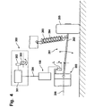
- FIG. 4 the parts, which correspond to the parts of Figures 1-3, with the same reference numerals Mistake.
- Figure 4 shows the better For clarity, only the relevant components here.
- the chassis and the chassis of the vehicle are denoted by the reference numeral 200 and 201.
- the chassis 201 includes front and rear control arms 202 made of steel or aluminum, which are hinged to the chassis 200.
- FIG. 4 shows the sake of clarity, only a wishbone.
- the associated Strut and the shock absorber and the wheel are denoted by the reference numeral 203, 204 and 205.
- the wishbone 202 sets in relation to the horizontal plane 206 of the vehicle, i. the terrain surface at a level Terrain, moving vehicle part, while the chassis 200 a respect the plane is stationary vehicle part.
- the sensor inductance L of the device 100 for determining the pitch position of the vehicle is at the chassis 206 stationary with respect to the plane 206 appropriate.
- the half-open pot core 12 of the annular coil 13 of the Sensor inductance L is the wishbone 202 of metal opposite.
- the signal transmission between the device 100 for determining the Nick position and the device 300 for regulating the lighting range done via a data bus 304.
- the device 300 for headlamp leveling has a control unit 301, which drives a servomotor 302, the inclination of a headlamp 303rd relative to reference plane 206 depending on the pitch position.
- the controller 301 controls the servomotor 302 so that the Headlight 303 is moved upward.
- the controller 301 controls the servomotor 302 so that the Headlight 303 is moved upward.
- the controller 301 controls the servomotor 302 so that the Headlight 303 is moved upward.
- the controller 301 controls the servomotor 302 so that the Headlight 303 is moved upward.
- the controller 301 controls the servomotor 302 so that the Headlight 303 is moved upward.
- a correction is made in relation to the horizontal plane upwards opposite direction.
Landscapes
- Physics & Mathematics (AREA)
- General Physics & Mathematics (AREA)
- Engineering & Computer Science (AREA)
- Mechanical Engineering (AREA)
- Lighting Device Outwards From Vehicle And Optical Signal (AREA)
- Automobile Manufacture Line, Endless Track Vehicle, Trailer (AREA)
- Measurement Of Length, Angles, Or The Like Using Electric Or Magnetic Means (AREA)
- Length Measuring Devices With Unspecified Measuring Means (AREA)
- Vehicle Body Suspensions (AREA)
Abstract
Description
- Figur 1
- ein vereinfachtes Blockschaltbild mit den wesentlichen Komponenten der Vorrichtung zur Bestimmung der Nickposition eines Fahrzeug, die einen Oszillator mit einem Schwingkreis und eine Auswertschaltung umfasst,
- Figur 2
- eine detaillierte Darstellung die Oszillatorschaltung der Vorrichtung von Figur 1 in leicht modifizierter Form,
- Figur 3
- die Signalverläufe von VOUT und VSIN und VRE als Funktion der Zeit in Abhängigkeit vom Abstand des Target und
- Figur 4
- eine stark vereinfachte schematische Darstellung eines Fahrzeugs mit einer Einrichtung zur Regulierung der Leuchtweite der Fahrzeugscheinwerfer in Abhängigkeit von der Nickposition des Fahrzeug und einer Vorrichtung zur Bestimmung der Nickposition.
Claims (10)
- Vorrichtung zur Erfassung der Position eines ersten Fahrzeugteils in bezug auf ein zweites Fahrzeugteil, insbesondere zur Bestimmung der Nickposition eines Fahrzeugs für die Regulierung der Leuchtweite der Fahrzeugscheinwerfer, mit einem induktiven Messsystem (100) zum berührungslosen Bestimmen des Abstandes x zwischen dem ersten und zweiten Fahrzeugteil, das einen freischwingenden Oszillator (10) aufweist, der einen Schwingkreis (30) aufweist, der eine Sensorinduktivität L enthält, die an einem der beiden Fahrzeugteile anzuordnen ist,
dadurch gekennzeichnet, dass der Oszillator (10) zur Entdämpfung des Schwingkreises (30) einen Verstärker (15) aufweist, wobei der Schwingkreis in die Gegenkopplung des Verstärkers geschaltet ist, und
der Oszillator (10) zur Anregung des Schwingkreises (30) einen zwischen Ausgang (18) und Eingang (16) des Verstärkers (15) geschalteten Rückkopplungszweig (21) aufweist, der Mittel (19, 20) zum Erzeugen eines Rechteckspannungssignals VRE aus einem Wechselspannungssignal VSIN enthält. - Vorrichtung nach Anspruch 1,
dadurch gekennzeichnet, dass die Mittel zum Erzeugen eines Rechteckspannungssignals aus einem Wechselspannungssignal einen Pulsformer (19) und einen Treiber (20) aufweisen, die in Serie geschaltet sind. - Vorrichtung nach Anspruch 1 oder 2,
dadurch gekennzeichnet, dass der Schwingkreis (30) eine Parallelschaltung aus der Sensorinduktivität L und einer Kapazität C ist. - Vorrichtung nach Angaben der Ansprüche 1-3,
dadurch gekennzeichnet, dass die Sensorinduktivität L eine Ringspule (13) ist, die in einem halboffenen Schalenkern (12) angeordnet ist. - Vorrichtung nach Angaben der Ansprüche 1 - 4,
dadurch gekennzeichnet, dass eine Auswertschaltung (50) vorgesehen ist, die aus dem vom Oszillator (10) erzeugten Wechselspannungssignal VSIN ein mit dem Abstand, insbesondere mit der Nickposition des Fahrzeugs, korrelierendes elektrisches Messsignal erzeugt. - Vorrichtung nach Anspruch 5,
dadurch gekennzeichnet, dass die Auswertschaltung (50) Mittel (51) zum Gleichrichten des vom Oszillator (10) erzeugten Wechselspannungssignals VSIN aufweist. - Vorrichtung nach Anspruch 5 oder 6,
dadurch gekennzeichnet, dass die Auswertschaltung (50) Mittel (55,56) zur Linearisierung und/oder Temperaturkompensation aufweist. - Vorrichtung nach Anspruch 7,
dadurch gekennzeichnet, dass die Mittel zur Linearisierung und/oder Temperaturkompensation einen Mikrocontroller (55) aufweisen. - Fahrzeug mit einer Einrichtung (300) zur Regulierung der Leuchtweite der Fahrzeugscheinwerfer (303) in Abhängigkeit von der Nickposition des Fahrzeugs und einer Vorrichtung (100) nach einem der Ansprüche 1-12, wobei das Fahrzeug in bezug auf eine horizontale Ebene (206) ortsfeste Fahrzeugteile (200) und gegenüber der horizontalen Ebene bewegliche Fahrzeugteile (202) aufweist, die einander gegenüberliegend angeordnet sind, dadurch gekennzeichnet, dass die Sensorinduktivität L an einem ortsfesten oder beweglichen Fahrzeugteil (200, 202) angeordnet ist, wobei das der Sensorinduktivität gegenüberliegende Fahrzeugteil (202, 201) ein Metallteil ist.
- Fahrzeug nach Anspruch 9,
dadurch gekennzeichnet, dass die Sensorinduktivität L an einem ortsfesten Fahrzeugteil (202) angeordnet ist, wobei das bewegliche Fahrzeugteil ein der Sensorinduktivität gegenüberliegender Querlenker (202) des Fahrzeugs ist.
Priority Applications (2)
| Application Number | Priority Date | Filing Date | Title |
|---|---|---|---|
| SI200430852T SI1512937T1 (sl) | 2003-09-05 | 2004-09-06 | Priprava za zajemanje položaja prvega dela vozila glede na drugi del vozila, predvsem za določanje položaja kinkanja vozila in vozilo s tovrstno pripravo |
| PL04021163T PL1512937T3 (pl) | 2003-09-05 | 2004-09-06 | Urządzenie do wykrywania położenia pierwszej części pojazdu w odniesieniu do drugiej części pojazdu, zwłaszcza do określania pochylenia pojazdu, i pojazd z tego rodzaju urządzeniem |
Applications Claiming Priority (2)
| Application Number | Priority Date | Filing Date | Title |
|---|---|---|---|
| DE10341485A DE10341485B4 (de) | 2003-09-05 | 2003-09-05 | Vorrichtung zur Erfassung der Position eines ersten Fahrzeugteils in bezug auf ein zweites Fahrzeugteil, insbesondere zur Bestimmung der Nickposition eines Fahrzeuges und Fahrzeug mit einer derartigen Vorrichtung |
| DE10341485 | 2003-09-05 |
Publications (3)
| Publication Number | Publication Date |
|---|---|
| EP1512937A2 true EP1512937A2 (de) | 2005-03-09 |
| EP1512937A3 EP1512937A3 (de) | 2007-03-28 |
| EP1512937B1 EP1512937B1 (de) | 2008-06-18 |
Family
ID=34129707
Family Applications (1)
| Application Number | Title | Priority Date | Filing Date |
|---|---|---|---|
| EP04021163A Expired - Lifetime EP1512937B1 (de) | 2003-09-05 | 2004-09-06 | Vorrichtung zur Erfassung der Position eines ersten Fahrzeugteils in Bezug auf ein zweites Fahrzeugteil, insbesondere zur Bestimmung der Nickposition eines Fahrzeuges und Fahrzeug mit einer derartigen Vorrichtung |
Country Status (8)
| Country | Link |
|---|---|
| EP (1) | EP1512937B1 (de) |
| AT (1) | ATE398761T1 (de) |
| DE (2) | DE10341485B4 (de) |
| DK (1) | DK1512937T3 (de) |
| ES (1) | ES2304572T3 (de) |
| PL (1) | PL1512937T3 (de) |
| PT (1) | PT1512937E (de) |
| SI (1) | SI1512937T1 (de) |
Cited By (3)
| Publication number | Priority date | Publication date | Assignee | Title |
|---|---|---|---|---|
| WO2007079955A3 (de) * | 2005-12-29 | 2007-10-11 | Knorr Bremse Systeme | Auswertungs- und kompensationsschaltung für einen induktiven wegsensor |
| FR2945246A1 (fr) * | 2009-05-05 | 2010-11-12 | Benedictus Haest | Procede et dispositif de correction des vibrations d'un faisceau emis par un element optique de vehicule |
| US20140035597A1 (en) * | 2012-07-31 | 2014-02-06 | Casco Schoeller Gmbh | Vehicle With Inductive Measuring Unit For Detecting Position Of Vehicle Part |
Families Citing this family (2)
| Publication number | Priority date | Publication date | Assignee | Title |
|---|---|---|---|---|
| DE102011102796A1 (de) | 2011-05-23 | 2012-11-29 | Trw Automotive Electronics & Components Gmbh | Positionssensor, Aktor-Sensor-Vorrichtung und Verfahren zur induktiven Erfassung einer Position |
| DE102011121028B4 (de) * | 2011-12-14 | 2014-10-16 | Paragon Ag | "Messanordnung zur Bestimmung des Abstands zu einer magnetischen Wechselfeldquelle und Verfahren zur Messung des Abstands zwischen einer Magnetsensoranordnung und einer magnetischen Wechselfeldquelle" |
Family Cites Families (12)
| Publication number | Priority date | Publication date | Assignee | Title |
|---|---|---|---|---|
| DE2329363A1 (de) * | 1973-06-08 | 1975-01-02 | Bosch Gmbh Robert | Geber fuer die regelung der leuchtweite von kraftfahrzeug-scheinwerfern |
| DE3334033A1 (de) * | 1983-09-21 | 1985-04-11 | Robert Bosch Gmbh, 7000 Stuttgart | Scheinwerfer fuer kraftfahrzeuge |
| DE3772515D1 (de) * | 1986-10-30 | 1991-10-02 | Ifm Electronic Gmbh | Elektronisches, beruehrungslos arbeitendes schaltgeraet. |
| DE3733944A1 (de) * | 1987-10-07 | 1989-04-27 | Andrae Leonberg Gmbh | Induktiver naeherungssensor |
| DE3839427C2 (de) * | 1988-11-23 | 1993-10-28 | Vogt Electronic Ag | Einrichtung zur automatischen Regelung der Leuchtweite der Scheinwerfer von Kraftfahrzeugen |
| DE4311669C2 (de) * | 1993-04-08 | 2002-06-13 | Bosch Gmbh Robert | Einrichtung zum Einstellen der Leuchtweite von Scheinwerfern bei Fahrzeugen |
| DE9412765U1 (de) * | 1994-08-08 | 1994-10-13 | Becker, Wolf-Jürgen, Univ.-Prof. Dr.rer.nat., 34119 Kassel | Induktiver Näherungssensor zur materialunabhängigen Abstandsmessung |
| DE19611810C2 (de) * | 1996-03-26 | 2000-12-28 | Balluff Gebhard Gmbh & Co | Berührungslos arbeitender Näherungsschalter |
| DE19748602A1 (de) * | 1997-11-04 | 1999-05-06 | Peine Salzgitter Verkehr | Achszählschalter |
| JP3849829B2 (ja) * | 1998-04-27 | 2006-11-22 | 株式会社デンソー | 車高センサ及び車両用前照灯光軸調整装置 |
| DE10000730C2 (de) * | 2000-01-11 | 2003-12-04 | Balluff Gmbh | Abstandssensor |
| DE10221873A1 (de) * | 2002-05-15 | 2003-11-27 | Zf Lemfoerder Metallwaren Ag | Gummilager mit Einfederungssensor |
-
2003
- 2003-09-05 DE DE10341485A patent/DE10341485B4/de not_active Expired - Fee Related
-
2004
- 2004-09-06 AT AT04021163T patent/ATE398761T1/de not_active IP Right Cessation
- 2004-09-06 PT PT04021163T patent/PT1512937E/pt unknown
- 2004-09-06 ES ES04021163T patent/ES2304572T3/es not_active Expired - Lifetime
- 2004-09-06 PL PL04021163T patent/PL1512937T3/pl unknown
- 2004-09-06 SI SI200430852T patent/SI1512937T1/sl unknown
- 2004-09-06 DE DE502004007378T patent/DE502004007378D1/de not_active Expired - Lifetime
- 2004-09-06 DK DK04021163T patent/DK1512937T3/da active
- 2004-09-06 EP EP04021163A patent/EP1512937B1/de not_active Expired - Lifetime
Cited By (4)
| Publication number | Priority date | Publication date | Assignee | Title |
|---|---|---|---|---|
| WO2007079955A3 (de) * | 2005-12-29 | 2007-10-11 | Knorr Bremse Systeme | Auswertungs- und kompensationsschaltung für einen induktiven wegsensor |
| US8008909B2 (en) | 2005-12-29 | 2011-08-30 | Knorr-Bremse Systeme Fuer Nutzfahrzeuge Gmbh | Analysis and compensation circuit for an inductive displacement sensor |
| FR2945246A1 (fr) * | 2009-05-05 | 2010-11-12 | Benedictus Haest | Procede et dispositif de correction des vibrations d'un faisceau emis par un element optique de vehicule |
| US20140035597A1 (en) * | 2012-07-31 | 2014-02-06 | Casco Schoeller Gmbh | Vehicle With Inductive Measuring Unit For Detecting Position Of Vehicle Part |
Also Published As
| Publication number | Publication date |
|---|---|
| PL1512937T3 (pl) | 2008-11-28 |
| DE10341485B4 (de) | 2005-08-25 |
| SI1512937T1 (sl) | 2008-12-31 |
| PT1512937E (pt) | 2008-08-21 |
| EP1512937A3 (de) | 2007-03-28 |
| DE502004007378D1 (de) | 2008-07-31 |
| DK1512937T3 (da) | 2008-10-27 |
| ATE398761T1 (de) | 2008-07-15 |
| ES2304572T3 (es) | 2008-10-16 |
| DE10341485A1 (de) | 2005-04-14 |
| EP1512937B1 (de) | 2008-06-18 |
Similar Documents
| Publication | Publication Date | Title |
|---|---|---|
| DE69310577T2 (de) | Positionssensorsystem | |
| EP2527795B1 (de) | Positionssensor, Aktor-Sensor-Vorrichtung und Verfahren zur induktiven Erfassung einer Position | |
| DE69206936T2 (de) | Geräte und Methode zur Eichung eines Niveauregelungsmoduls | |
| WO2001026228A1 (de) | Näherungssensor und verfahren zu seinem betrieb | |
| DE19918404A1 (de) | Höhensensor und Gerät zum Einstellen der Strahlachse eines Fahrzeugscheinwerfers | |
| DE1931399B2 (de) | Vorrichtung zur uebertragung von zustandssignalen zwischen zwei gegenseitig bewegten gegenstaenden | |
| EP0071873A2 (de) | Schaltungsanordnung zum Wahrnehmen von Gegenständen mit einer Leiterschleife | |
| DE2052102A1 (de) | ||
| DE3500409C2 (de) | ||
| EP1959570A2 (de) | Induktiver Nährungssensor | |
| DE2810664C2 (de) | Anordnung zum Spurführen eines gleisfreien Fahrzeuges | |
| WO2000029701A1 (de) | Vorrichtung zum erfassen der verstellung translatorisch bewegter verstelleinrichtungen in fahrzeugen | |
| EP1512937B1 (de) | Vorrichtung zur Erfassung der Position eines ersten Fahrzeugteils in Bezug auf ein zweites Fahrzeugteil, insbesondere zur Bestimmung der Nickposition eines Fahrzeuges und Fahrzeug mit einer derartigen Vorrichtung | |
| WO1990012289A1 (de) | Schaltungsanordnung und verfahren zur induktiven wegmessung | |
| DE102012015035B3 (de) | Fahrzeug mit einer induktiven Messeinheit zur Erfassung der Position eines Fahrzeugteils | |
| DE3821569A1 (de) | Vorrichtung zur ermittlung des einfederniveaus an einem ueber luftfederbaelge abgefederten und stossdaempfer gedaempften fahrzeug | |
| DE102012008699B4 (de) | Verfahren zur Vergrößerung der Meßreichweite einer Vorrichtung zur berührungslosen Messung eines Abstands | |
| DE102015221585B3 (de) | Verfahren zum Betreiben einer Ladevorrichtung zum induktiven Laden eines elektrischen Energiespeichers eines Kraftfahrzeugs, Ladevorrichtung sowie Anordnung | |
| DE102007053881B4 (de) | Messverfahren und Messvorrichtung zur induktiven Winkel- und/oder Positionsbestimmung | |
| DE3839427C2 (de) | Einrichtung zur automatischen Regelung der Leuchtweite der Scheinwerfer von Kraftfahrzeugen | |
| EP3345302B1 (de) | Induktiver näherungsschalter mit einem mikrocontroller | |
| WO1995013532A1 (de) | Verfahren zur messung der temperatur von metallischen werkstücken und ihres feststoffanteils im teilerstarrten zustand | |
| AT413373B (de) | Schaltungsanordnung zum abgleichen von induktiven sensoren | |
| DE102018102611A1 (de) | Sensor, System und Verfahren zum Erfassen von Metallteilen | |
| EP1375205B1 (de) | Sensor zur Erfassung der Lage zweier relativ zueinander beweglicher Teile |
Legal Events
| Date | Code | Title | Description |
|---|---|---|---|
| PUAI | Public reference made under article 153(3) epc to a published international application that has entered the european phase |
Free format text: ORIGINAL CODE: 0009012 |
|
| AK | Designated contracting states |
Kind code of ref document: A2 Designated state(s): AT BE BG CH CY CZ DE DK EE ES FI FR GB GR HU IE IT LI LU MC NL PL PT RO SE SI SK TR |
|
| AX | Request for extension of the european patent |
Extension state: AL HR LT LV MK |
|
| PUAL | Search report despatched |
Free format text: ORIGINAL CODE: 0009013 |
|
| AK | Designated contracting states |
Kind code of ref document: A3 Designated state(s): AT BE BG CH CY CZ DE DK EE ES FI FR GB GR HU IE IT LI LU MC NL PL PT RO SE SI SK TR |
|
| AX | Request for extension of the european patent |
Extension state: AL HR LT LV MK |
|
| 17P | Request for examination filed |
Effective date: 20070914 |
|
| AKX | Designation fees paid |
Designated state(s): AT BE BG CH CY CZ DE DK EE ES FI FR GB GR HU IE IT LI LU MC NL PL PT RO SE SI SK TR |
|
| GRAP | Despatch of communication of intention to grant a patent |
Free format text: ORIGINAL CODE: EPIDOSNIGR1 |
|
| GRAS | Grant fee paid |
Free format text: ORIGINAL CODE: EPIDOSNIGR3 |
|
| GRAA | (expected) grant |
Free format text: ORIGINAL CODE: 0009210 |
|
| AK | Designated contracting states |
Kind code of ref document: B1 Designated state(s): AT BE BG CH CY CZ DE DK EE ES FI FR GB GR HU IE IT LI LU MC NL PL PT RO SE SI SK TR |
|
| REG | Reference to a national code |
Ref country code: GB Ref legal event code: FG4D Free format text: NOT ENGLISH |
|
| REF | Corresponds to: |
Ref document number: 502004007378 Country of ref document: DE Date of ref document: 20080731 Kind code of ref document: P |
|
| REG | Reference to a national code |
Ref country code: CH Ref legal event code: EP |
|
| REG | Reference to a national code |
Ref country code: IE Ref legal event code: FG4D Free format text: LANGUAGE OF EP DOCUMENT: GERMAN |
|
| REG | Reference to a national code |
Ref country code: PT Ref legal event code: SC4A Free format text: AVAILABILITY OF NATIONAL TRANSLATION Effective date: 20080811 |
|
| REG | Reference to a national code |
Ref country code: RO Ref legal event code: EPE |
|
| REG | Reference to a national code |
Ref country code: SE Ref legal event code: TRGR |
|
| REG | Reference to a national code |
Ref country code: GR Ref legal event code: EP Ref document number: 20080402279 Country of ref document: GR |
|
| REG | Reference to a national code |
Ref country code: ES Ref legal event code: FG2A Ref document number: 2304572 Country of ref document: ES Kind code of ref document: T3 |
|
| PGFP | Annual fee paid to national office [announced via postgrant information from national office to epo] |
Ref country code: BG Payment date: 20080929 Year of fee payment: 5 Ref country code: CH Payment date: 20080923 Year of fee payment: 5 Ref country code: DK Payment date: 20080922 Year of fee payment: 5 Ref country code: EE Payment date: 20080922 Year of fee payment: 5 Ref country code: LU Payment date: 20080923 Year of fee payment: 5 Ref country code: PT Payment date: 20080924 Year of fee payment: 5 Ref country code: SI Payment date: 20080923 Year of fee payment: 5 |
|
| PGFP | Annual fee paid to national office [announced via postgrant information from national office to epo] |
Ref country code: AT Payment date: 20080919 Year of fee payment: 5 Ref country code: FI Payment date: 20080923 Year of fee payment: 5 Ref country code: IE Payment date: 20080918 Year of fee payment: 5 Ref country code: MC Payment date: 20080919 Year of fee payment: 5 Ref country code: NL Payment date: 20080922 Year of fee payment: 5 Ref country code: PL Payment date: 20080923 Year of fee payment: 5 Ref country code: RO Payment date: 20080908 Year of fee payment: 5 Ref country code: SK Payment date: 20080929 Year of fee payment: 5 |
|
| REG | Reference to a national code |
Ref country code: HU Ref legal event code: AG4A Ref document number: E003754 Country of ref document: HU Ref country code: PL Ref legal event code: T3 |
|
| PGFP | Annual fee paid to national office [announced via postgrant information from national office to epo] |
Ref country code: BE Payment date: 20080924 Year of fee payment: 5 |
|
| PLBE | No opposition filed within time limit |
Free format text: ORIGINAL CODE: 0009261 |
|
| STAA | Information on the status of an ep patent application or granted ep patent |
Free format text: STATUS: NO OPPOSITION FILED WITHIN TIME LIMIT |
|
| 26N | No opposition filed |
Effective date: 20090319 |
|
| PGFP | Annual fee paid to national office [announced via postgrant information from national office to epo] |
Ref country code: CZ Payment date: 20090304 Year of fee payment: 6 |
|
| PGFP | Annual fee paid to national office [announced via postgrant information from national office to epo] |
Ref country code: GR Payment date: 20080926 Year of fee payment: 5 |
|
| PGFP | Annual fee paid to national office [announced via postgrant information from national office to epo] |
Ref country code: CY Payment date: 20080930 Year of fee payment: 5 |
|
| REG | Reference to a national code |
Ref country code: PT Ref legal event code: MM4A Free format text: LAPSE DUE TO NON-PAYMENT OF FEES Effective date: 20100308 |
|
| BERE | Be: lapsed |
Owner name: CASCO SCHOELLER G.M.B.H. Effective date: 20090930 |
|
| PGFP | Annual fee paid to national office [announced via postgrant information from national office to epo] |
Ref country code: HU Payment date: 20081006 Year of fee payment: 5 |
|
| REG | Reference to a national code |
Ref country code: NL Ref legal event code: V1 Effective date: 20100401 |
|
| PG25 | Lapsed in a contracting state [announced via postgrant information from national office to epo] |
Ref country code: PT Free format text: LAPSE BECAUSE OF NON-PAYMENT OF DUE FEES Effective date: 20100308 Ref country code: MC Free format text: LAPSE BECAUSE OF NON-PAYMENT OF DUE FEES Effective date: 20090930 Ref country code: FI Free format text: LAPSE BECAUSE OF NON-PAYMENT OF DUE FEES Effective date: 20090906 Ref country code: RO Free format text: LAPSE BECAUSE OF NON-PAYMENT OF DUE FEES Effective date: 20090906 |
|
| REG | Reference to a national code |
Ref country code: CH Ref legal event code: PL |
|
| REG | Reference to a national code |
Ref country code: DK Ref legal event code: EBP |
|
| PG25 | Lapsed in a contracting state [announced via postgrant information from national office to epo] |
Ref country code: CY Free format text: LAPSE BECAUSE OF NON-PAYMENT OF DUE FEES Effective date: 20090906 |
|
| REG | Reference to a national code |
Ref country code: SK Ref legal event code: MM4A Ref document number: E 4008 Country of ref document: SK Effective date: 20090906 |
|
| REG | Reference to a national code |
Ref country code: EE Ref legal event code: MM4A Ref document number: E002367 Country of ref document: EE Effective date: 20090930 |
|
| REG | Reference to a national code |
Ref country code: IE Ref legal event code: MM4A |
|
| PG25 | Lapsed in a contracting state [announced via postgrant information from national office to epo] |
Ref country code: AT Free format text: LAPSE BECAUSE OF NON-PAYMENT OF DUE FEES Effective date: 20090906 |
|
| REG | Reference to a national code |
Ref country code: SI Ref legal event code: KO00 Effective date: 20100430 |
|
| PG25 | Lapsed in a contracting state [announced via postgrant information from national office to epo] |
Ref country code: EE Free format text: LAPSE BECAUSE OF NON-PAYMENT OF DUE FEES Effective date: 20090930 Ref country code: HU Free format text: LAPSE BECAUSE OF NON-PAYMENT OF DUE FEES Effective date: 20090907 Ref country code: BG Free format text: LAPSE BECAUSE OF THE APPLICANT RENOUNCES Effective date: 20100331 Ref country code: IE Free format text: LAPSE BECAUSE OF NON-PAYMENT OF DUE FEES Effective date: 20090907 Ref country code: NL Free format text: LAPSE BECAUSE OF NON-PAYMENT OF DUE FEES Effective date: 20100401 |
|
| PG25 | Lapsed in a contracting state [announced via postgrant information from national office to epo] |
Ref country code: BE Free format text: LAPSE BECAUSE OF NON-PAYMENT OF DUE FEES Effective date: 20090930 Ref country code: SI Free format text: LAPSE BECAUSE OF NON-PAYMENT OF DUE FEES Effective date: 20090907 Ref country code: SK Free format text: LAPSE BECAUSE OF NON-PAYMENT OF DUE FEES Effective date: 20090906 |
|
| PG25 | Lapsed in a contracting state [announced via postgrant information from national office to epo] |
Ref country code: GR Free format text: LAPSE BECAUSE OF NON-PAYMENT OF DUE FEES Effective date: 20100406 Ref country code: LI Free format text: LAPSE BECAUSE OF NON-PAYMENT OF DUE FEES Effective date: 20090930 Ref country code: CH Free format text: LAPSE BECAUSE OF NON-PAYMENT OF DUE FEES Effective date: 20090930 |
|
| PG25 | Lapsed in a contracting state [announced via postgrant information from national office to epo] |
Ref country code: DK Free format text: LAPSE BECAUSE OF NON-PAYMENT OF DUE FEES Effective date: 20090930 |
|
| PG25 | Lapsed in a contracting state [announced via postgrant information from national office to epo] |
Ref country code: LU Free format text: LAPSE BECAUSE OF NON-PAYMENT OF DUE FEES Effective date: 20090906 |
|
| PG25 | Lapsed in a contracting state [announced via postgrant information from national office to epo] |
Ref country code: PL Free format text: LAPSE BECAUSE OF NON-PAYMENT OF DUE FEES Effective date: 20090906 Ref country code: CZ Free format text: LAPSE BECAUSE OF NON-PAYMENT OF DUE FEES Effective date: 20100906 |
|
| REG | Reference to a national code |
Ref country code: PL Ref legal event code: LAPE |
|
| PGFP | Annual fee paid to national office [announced via postgrant information from national office to epo] |
Ref country code: TR Payment date: 20080923 Year of fee payment: 5 |
|
| PGFP | Annual fee paid to national office [announced via postgrant information from national office to epo] |
Ref country code: GB Payment date: 20120920 Year of fee payment: 9 Ref country code: SE Payment date: 20120920 Year of fee payment: 9 |
|
| PGFP | Annual fee paid to national office [announced via postgrant information from national office to epo] |
Ref country code: ES Payment date: 20120924 Year of fee payment: 9 Ref country code: IT Payment date: 20120925 Year of fee payment: 9 |
|
| PG25 | Lapsed in a contracting state [announced via postgrant information from national office to epo] |
Ref country code: TR Free format text: LAPSE BECAUSE OF NON-PAYMENT OF DUE FEES Effective date: 20090906 |
|
| PGFP | Annual fee paid to national office [announced via postgrant information from national office to epo] |
Ref country code: FR Payment date: 20121008 Year of fee payment: 9 |
|
| REG | Reference to a national code |
Ref country code: DE Ref legal event code: R082 Ref document number: 502004007378 Country of ref document: DE Representative=s name: OPPERMANN, FRANK, DIPL.-ING., DE |
|
| REG | Reference to a national code |
Ref country code: SE Ref legal event code: EUG |
|
| PG25 | Lapsed in a contracting state [announced via postgrant information from national office to epo] |
Ref country code: SE Free format text: LAPSE BECAUSE OF NON-PAYMENT OF DUE FEES Effective date: 20130907 |
|
| GBPC | Gb: european patent ceased through non-payment of renewal fee |
Effective date: 20130906 |
|
| REG | Reference to a national code |
Ref country code: FR Ref legal event code: ST Effective date: 20140530 |
|
| PG25 | Lapsed in a contracting state [announced via postgrant information from national office to epo] |
Ref country code: GB Free format text: LAPSE BECAUSE OF NON-PAYMENT OF DUE FEES Effective date: 20130906 |
|
| PG25 | Lapsed in a contracting state [announced via postgrant information from national office to epo] |
Ref country code: IT Free format text: LAPSE BECAUSE OF NON-PAYMENT OF DUE FEES Effective date: 20130906 Ref country code: FR Free format text: LAPSE BECAUSE OF NON-PAYMENT OF DUE FEES Effective date: 20130930 |
|
| REG | Reference to a national code |
Ref country code: ES Ref legal event code: FD2A Effective date: 20150506 |
|
| PG25 | Lapsed in a contracting state [announced via postgrant information from national office to epo] |
Ref country code: ES Free format text: LAPSE BECAUSE OF NON-PAYMENT OF DUE FEES Effective date: 20130907 |
|
| PGFP | Annual fee paid to national office [announced via postgrant information from national office to epo] |
Ref country code: DE Payment date: 20180809 Year of fee payment: 15 |
|
| REG | Reference to a national code |
Ref country code: DE Ref legal event code: R119 Ref document number: 502004007378 Country of ref document: DE |
|
| PG25 | Lapsed in a contracting state [announced via postgrant information from national office to epo] |
Ref country code: DE Free format text: LAPSE BECAUSE OF NON-PAYMENT OF DUE FEES Effective date: 20200401 |