EP1512870A1 - Schrägscheibenverdichter mit veränderlicher Fördermenge - Google Patents
Schrägscheibenverdichter mit veränderlicher Fördermenge Download PDFInfo
- Publication number
- EP1512870A1 EP1512870A1 EP04021039A EP04021039A EP1512870A1 EP 1512870 A1 EP1512870 A1 EP 1512870A1 EP 04021039 A EP04021039 A EP 04021039A EP 04021039 A EP04021039 A EP 04021039A EP 1512870 A1 EP1512870 A1 EP 1512870A1
- Authority
- EP
- European Patent Office
- Prior art keywords
- swash plate
- clutch
- guiding member
- compressor according
- boss
- Prior art date
- Legal status (The legal status is an assumption and is not a legal conclusion. Google has not performed a legal analysis and makes no representation as to the accuracy of the status listed.)
- Withdrawn
Links
- 238000006073 displacement reaction Methods 0.000 title claims abstract description 48
- 230000006835 compression Effects 0.000 claims description 33
- 238000007906 compression Methods 0.000 claims description 33
- 239000000314 lubricant Substances 0.000 claims description 20
- 238000006243 chemical reaction Methods 0.000 claims description 17
- 230000005856 abnormality Effects 0.000 claims description 12
- 230000009467 reduction Effects 0.000 abstract description 3
- 230000002829 reductive effect Effects 0.000 description 28
- 230000000670 limiting effect Effects 0.000 description 27
- 230000008901 benefit Effects 0.000 description 24
- 239000003507 refrigerant Substances 0.000 description 21
- 230000007246 mechanism Effects 0.000 description 18
- 230000004048 modification Effects 0.000 description 13
- 238000012986 modification Methods 0.000 description 13
- 230000005540 biological transmission Effects 0.000 description 11
- 230000005611 electricity Effects 0.000 description 11
- 230000036961 partial effect Effects 0.000 description 11
- 230000003247 decreasing effect Effects 0.000 description 8
- 230000006870 function Effects 0.000 description 6
- 230000007423 decrease Effects 0.000 description 4
- 238000000034 method Methods 0.000 description 4
- 230000008569 process Effects 0.000 description 4
- ATJFFYVFTNAWJD-UHFFFAOYSA-N Tin Chemical compound [Sn] ATJFFYVFTNAWJD-UHFFFAOYSA-N 0.000 description 3
- 230000001133 acceleration Effects 0.000 description 3
- 239000000446 fuel Substances 0.000 description 3
- 238000005259 measurement Methods 0.000 description 3
- 230000002093 peripheral effect Effects 0.000 description 3
- -1 polytetrafluoroethylene Polymers 0.000 description 3
- 229920001343 polytetrafluoroethylene Polymers 0.000 description 3
- 239000004810 polytetrafluoroethylene Substances 0.000 description 3
- 239000000843 powder Substances 0.000 description 3
- XEEYBQQBJWHFJM-UHFFFAOYSA-N Iron Chemical compound [Fe] XEEYBQQBJWHFJM-UHFFFAOYSA-N 0.000 description 2
- 240000005860 Portulaca grandiflora Species 0.000 description 2
- 230000002411 adverse Effects 0.000 description 2
- 238000013459 approach Methods 0.000 description 2
- 238000001816 cooling Methods 0.000 description 2
- 230000002349 favourable effect Effects 0.000 description 2
- 239000000463 material Substances 0.000 description 2
- 239000002184 metal Substances 0.000 description 2
- 229910052751 metal Inorganic materials 0.000 description 2
- RYGMFSIKBFXOCR-UHFFFAOYSA-N Copper Chemical compound [Cu] RYGMFSIKBFXOCR-UHFFFAOYSA-N 0.000 description 1
- 230000009471 action Effects 0.000 description 1
- 238000004378 air conditioning Methods 0.000 description 1
- 230000008859 change Effects 0.000 description 1
- 244000145845 chattering Species 0.000 description 1
- 238000002485 combustion reaction Methods 0.000 description 1
- 229910052802 copper Inorganic materials 0.000 description 1
- 239000010949 copper Substances 0.000 description 1
- 230000000994 depressogenic effect Effects 0.000 description 1
- 238000013461 design Methods 0.000 description 1
- 230000006866 deterioration Effects 0.000 description 1
- 230000005674 electromagnetic induction Effects 0.000 description 1
- 230000004907 flux Effects 0.000 description 1
- 230000006872 improvement Effects 0.000 description 1
- 229910052742 iron Inorganic materials 0.000 description 1
- 238000005057 refrigeration Methods 0.000 description 1
- 230000004044 response Effects 0.000 description 1
- 238000005096 rolling process Methods 0.000 description 1
- 238000007789 sealing Methods 0.000 description 1
Images


Classifications
-
- F—MECHANICAL ENGINEERING; LIGHTING; HEATING; WEAPONS; BLASTING
- F04—POSITIVE - DISPLACEMENT MACHINES FOR LIQUIDS; PUMPS FOR LIQUIDS OR ELASTIC FLUIDS
- F04B—POSITIVE-DISPLACEMENT MACHINES FOR LIQUIDS; PUMPS
- F04B27/00—Multi-cylinder pumps specially adapted for elastic fluids and characterised by number or arrangement of cylinders
- F04B27/08—Multi-cylinder pumps specially adapted for elastic fluids and characterised by number or arrangement of cylinders having cylinders coaxial with, or parallel or inclined to, main shaft axis
- F04B27/14—Control
- F04B27/16—Control of pumps with stationary cylinders
- F04B27/18—Control of pumps with stationary cylinders by varying the relative positions of a swash plate and a cylinder block
- F04B27/1804—Controlled by crankcase pressure
-
- F—MECHANICAL ENGINEERING; LIGHTING; HEATING; WEAPONS; BLASTING
- F04—POSITIVE - DISPLACEMENT MACHINES FOR LIQUIDS; PUMPS FOR LIQUIDS OR ELASTIC FLUIDS
- F04B—POSITIVE-DISPLACEMENT MACHINES FOR LIQUIDS; PUMPS
- F04B27/00—Multi-cylinder pumps specially adapted for elastic fluids and characterised by number or arrangement of cylinders
- F04B27/08—Multi-cylinder pumps specially adapted for elastic fluids and characterised by number or arrangement of cylinders having cylinders coaxial with, or parallel or inclined to, main shaft axis
- F04B27/0873—Component parts, e.g. sealings; Manufacturing or assembly thereof
- F04B27/0895—Component parts, e.g. sealings; Manufacturing or assembly thereof driving means
-
- F—MECHANICAL ENGINEERING; LIGHTING; HEATING; WEAPONS; BLASTING
- F04—POSITIVE - DISPLACEMENT MACHINES FOR LIQUIDS; PUMPS FOR LIQUIDS OR ELASTIC FLUIDS
- F04B—POSITIVE-DISPLACEMENT MACHINES FOR LIQUIDS; PUMPS
- F04B27/00—Multi-cylinder pumps specially adapted for elastic fluids and characterised by number or arrangement of cylinders
- F04B27/08—Multi-cylinder pumps specially adapted for elastic fluids and characterised by number or arrangement of cylinders having cylinders coaxial with, or parallel or inclined to, main shaft axis
- F04B27/10—Multi-cylinder pumps specially adapted for elastic fluids and characterised by number or arrangement of cylinders having cylinders coaxial with, or parallel or inclined to, main shaft axis having stationary cylinders
- F04B27/1036—Component parts, details, e.g. sealings, lubrication
- F04B27/1054—Actuating elements
- F04B27/1063—Actuating-element bearing means or driving-axis bearing means
-
- F—MECHANICAL ENGINEERING; LIGHTING; HEATING; WEAPONS; BLASTING
- F16—ENGINEERING ELEMENTS AND UNITS; GENERAL MEASURES FOR PRODUCING AND MAINTAINING EFFECTIVE FUNCTIONING OF MACHINES OR INSTALLATIONS; THERMAL INSULATION IN GENERAL
- F16C—SHAFTS; FLEXIBLE SHAFTS; ELEMENTS OR CRANKSHAFT MECHANISMS; ROTARY BODIES OTHER THAN GEARING ELEMENTS; BEARINGS
- F16C17/00—Sliding-contact bearings for exclusively rotary movement
- F16C17/02—Sliding-contact bearings for exclusively rotary movement for radial load only
-
- F—MECHANICAL ENGINEERING; LIGHTING; HEATING; WEAPONS; BLASTING
- F16—ENGINEERING ELEMENTS AND UNITS; GENERAL MEASURES FOR PRODUCING AND MAINTAINING EFFECTIVE FUNCTIONING OF MACHINES OR INSTALLATIONS; THERMAL INSULATION IN GENERAL
- F16C—SHAFTS; FLEXIBLE SHAFTS; ELEMENTS OR CRANKSHAFT MECHANISMS; ROTARY BODIES OTHER THAN GEARING ELEMENTS; BEARINGS
- F16C19/00—Bearings with rolling contact, for exclusively rotary movement
- F16C19/02—Bearings with rolling contact, for exclusively rotary movement with bearing balls essentially of the same size in one or more circular rows
- F16C19/10—Bearings with rolling contact, for exclusively rotary movement with bearing balls essentially of the same size in one or more circular rows for axial load mainly
-
- F—MECHANICAL ENGINEERING; LIGHTING; HEATING; WEAPONS; BLASTING
- F05—INDEXING SCHEMES RELATING TO ENGINES OR PUMPS IN VARIOUS SUBCLASSES OF CLASSES F01-F04
- F05B—INDEXING SCHEME RELATING TO WIND, SPRING, WEIGHT, INERTIA OR LIKE MOTORS, TO MACHINES OR ENGINES FOR LIQUIDS COVERED BY SUBCLASSES F03B, F03D AND F03G
- F05B2240/00—Components
- F05B2240/50—Bearings
- F05B2240/52—Axial thrust bearings
-
- F—MECHANICAL ENGINEERING; LIGHTING; HEATING; WEAPONS; BLASTING
- F05—INDEXING SCHEMES RELATING TO ENGINES OR PUMPS IN VARIOUS SUBCLASSES OF CLASSES F01-F04
- F05B—INDEXING SCHEME RELATING TO WIND, SPRING, WEIGHT, INERTIA OR LIKE MOTORS, TO MACHINES OR ENGINES FOR LIQUIDS COVERED BY SUBCLASSES F03B, F03D AND F03G
- F05B2240/00—Components
- F05B2240/50—Bearings
- F05B2240/54—Radial bearings
-
- F—MECHANICAL ENGINEERING; LIGHTING; HEATING; WEAPONS; BLASTING
- F05—INDEXING SCHEMES RELATING TO ENGINES OR PUMPS IN VARIOUS SUBCLASSES OF CLASSES F01-F04
- F05B—INDEXING SCHEME RELATING TO WIND, SPRING, WEIGHT, INERTIA OR LIKE MOTORS, TO MACHINES OR ENGINES FOR LIQUIDS COVERED BY SUBCLASSES F03B, F03D AND F03G
- F05B2260/00—Function
- F05B2260/40—Transmission of power
-
- F—MECHANICAL ENGINEERING; LIGHTING; HEATING; WEAPONS; BLASTING
- F16—ENGINEERING ELEMENTS AND UNITS; GENERAL MEASURES FOR PRODUCING AND MAINTAINING EFFECTIVE FUNCTIONING OF MACHINES OR INSTALLATIONS; THERMAL INSULATION IN GENERAL
- F16C—SHAFTS; FLEXIBLE SHAFTS; ELEMENTS OR CRANKSHAFT MECHANISMS; ROTARY BODIES OTHER THAN GEARING ELEMENTS; BEARINGS
- F16C2360/00—Engines or pumps
- F16C2360/42—Pumps with cylinders or pistons
-
- Y—GENERAL TAGGING OF NEW TECHNOLOGICAL DEVELOPMENTS; GENERAL TAGGING OF CROSS-SECTIONAL TECHNOLOGIES SPANNING OVER SEVERAL SECTIONS OF THE IPC; TECHNICAL SUBJECTS COVERED BY FORMER USPC CROSS-REFERENCE ART COLLECTIONS [XRACs] AND DIGESTS
- Y10—TECHNICAL SUBJECTS COVERED BY FORMER USPC
- Y10S—TECHNICAL SUBJECTS COVERED BY FORMER USPC CROSS-REFERENCE ART COLLECTIONS [XRACs] AND DIGESTS
- Y10S417/00—Pumps
Definitions
- the present invention relates to a swash plate type variable displacement compressor, which is capable of changing its displacement.
- a swash plate type variable displacement compressor is typically used as a refrigerant compressor.
- the swash plate type variable displacement compressor includes a drive shaft coupled to an output shaft of an engine, a swash plate that is tiltably supported by and rotates integrally with the drive shaft, and pistons each engaged with the swash plate with shoes.
- the swash plate type variable displacement compressor has the configuration shown above, when swash plate rotates as the drive shaft rotates, the swash plate slides across the shoes and wobbles back and forth apparently in a direction along the axis of the drive shaft. Wobbling of the swash plate causes the pistons to reciprocate to compress gas. Also, by changing the inclination angle of the swash plate relative to the drive shaft, the stroke of the pistons is varied. Accordingly, the displacement of the swash plate type variable displacement compressor is changed.
- a clutchless type compressor is known as one of the swash plate type variable displacement compressors other than a clutch type compressor, which is another swash plate type variable displacement compressor equipped with a clutch in a power transmission mechanism between its drive shaft and an engine.
- the clutchless type compressor has no clutch in the power transmission mechanism and permits power of the engine to be constantly transmitted. That is, the drive shaft of the swash plate type variable displacement compressor having no clutch is constantly rotated by the drive shaft of the engine when the engine is running. Therefore, when cooling is not needed, the vehicle air conditioner causes the compressor to perform an "OFF operation", in which the displacement of the swash plate type variable displacement compressor is minimized. Accordingly, the load on the engine (load for driving the swash plate type variable displacement compressor) is reduced, thereby improving the fuel economy of the engine.
- the swash plate type variable displacement compressor having no clutch that is the clutchless type compressor, has shoes that slide on a swash plate. Therefore, mechanical loss due to frictional resistance at the contacting portions of the swash plate and the shoes is great, thereby increasing the load on the engine. Particularly, in the swash plate type variable displacement compressor having no clutch, mechanical loss at the contacting portions of the swash plate and the shoes have been desired to be reduced for the same of decreasing the load on the engine during the OFF operation.
- a swash plate guiding member is coupled to a drive shaft to rotate integrally with and incline relative to the drive shaft.
- a swash plate is supported by the guiding member with bearings.
- the guiding member rotates as the drive shaft rotates, the guiding member slips relative to the swash plate. Accordingly, the rotation speed of the swash plate is lower than that of the guiding member. Accordingly, the relative rotation speed of the swash plate and the shoes is lower than the relative rotation speed of the shoes and the guiding member. This reduces the mechanical loss at the contacting portions of the swash plate and the shoes. As a result, the load of the swash plate type variable displacement compressor acting on the engine is reduced.
- the swash plate since the rotation speed of the swash plate is lower than that of the guiding member in the above described improved swash plate type variable displacement compressor, the swash plate only receives a slight centrifugal force. Centrifugal force of the swash plate acts to cancel the inertial force of the piston, which is generated by reciprocation of the piston. Specifically, while the centrifugal force of the swash plate acts to decrease the inclination angle of the swash plate, the inertial force of the pistons act to increase the inclination angle of the swash plate.
- the prior art has a dilemma. That is, if the displacement control of a swash plate type variable displacement compressor is prioritized, the mechanical loss between the swash plate and the shoes is increased. Conversely, if reduction of mechanical loss generated between the swash plate and the shoes is prioritized, the displacement control of the swash plate type variable displacement compressor is degraded.
- a swash plate type variable displacement compressor that is capable of switching between a state where improving the displacement controllability is prioritized and a state where reduction of mechanical loss between the swash plate and the shoes is prioritized.
- the present invention provides a swash plate type variable displacement compressor.
- the compressor includes a drive shaft, a swash plate guiding member that is coupled to the drive shaft.
- the guiding member rotates integrally with and inclines relative to the drive shaft.
- the compressor further includes a swash plate supported by the guiding member, a shoe, and a piston engaged with the swash plate via the shoe.
- the piston reciprocates to compress gas.
- an inclination angle of the swash plate relative to the drive shaft is changed as the guiding member inclines, the stroke of the piston is changed to vary the displacement of the compressor.
- a clutch is located between the guiding member and the swash plate. The clutch is switched between an engaged state, where the clutch permits the guiding member and the swash plate to rotate integrally, and a disengaged state, where the clutch permits the guiding member and the swash plate to rotate relative to each other.
- Fig. 1 is a longitudinal cross-sectional view illustrating a swash plate type variable displacement compressor 10 used in a refrigerant circuit of a vehicle air conditioner.
- a housing 11 of the compressor 10 includes a cylinder block 12, a front housing member 13, and a rear housing member 14.
- the front housing member 13 is secured to one end (left end as viewed in the drawing) of the cylinder block 12.
- the rear housing member 14 is secured to the other end (right end as viewed in the drawing) of the cylinder block 12 with a valve assembly 15 in between.
- the left side is (the side corresponding to the front housing member 13) is referred to as. the front of the compressor 10, and the right side (the side corresponding to the rear housing member 14) is referred to as the rear of the compressor 10, as necessary.
- One end (front end) of a drive shaft 17 is rotatably supported by the front housing member 13.
- the other end (rear end) of the drive shaft 17 is rotatably supported by the cylinder block 12.
- the drive shaft 17 extends frontward and rearward in the housing 11 of the compressor 10 and through the crank chamber 16.
- the drive shaft 17 is connected to a drive source of the vehicle, which is an engine (internal combustion engine) E in this embodiment, through a power transmission mechanism PT.
- the power transmission mechanism PT is a clutchless mechanism that includes, for example, a belt and a pulley.
- the power transmission mechanism PT does not have a clutch mechanism (for example, an electromagnetic clutch) that selectively transmits and disconnects power with external electric control.
- the power transmission mechanism PT therefore constantly transmits power. Therefore, when the engine E is running, the drive shaft 17 constantly receives power from the engine E and rotates around an axis L.
- a substantially disk-shaped rotor 18 is accommodated in the crank chamber 16.
- the rotor 18 is fixed to the drive shaft 17 to rotate integrally with the drive shaft 17.
- a swash plate guiding member 19, which is made of an iron-based metal, is accommodated in the crank chamber 16.
- the guiding member 19 is located rearward of the rotor 18.
- a boss 19a is formed on a center of the rear side of the guiding member 19.
- a shaft receiving hole 19b is formed in a central portion of the guiding member 19 (including the boss 19a).
- the drive shaft 17 extends through the shaft receiving hole 19b and supports the guiding member 19 such that the guiding member 19 slides back and forth along the axis L of the drive shaft 17 and that the inclination angle of the guiding member 19 is variable.
- the inclination angle of the guiding member 19 relative to the drive shaft 17 refers to an angle defined by an imaginary plane perpendicular to a central axis M of the guiding member 19 or a central axis M of the boss 19a, and an imaginary plane perpendicular to the axis L of the drive shaft 17.
- the rotor 18 is connected to the guiding member 19 with a hinge mechanism 20.
- the hinge mechanism 20 is of a "pinless type".
- the hinge mechanism 20 has a pair of driving projections 21 protruding from the rear side of the rotor and a pair of driven projections 22 protruding toward the rotor 18 from the front side of the guiding member 19.
- the driven projections 22 are located between the driving projections 21.
- a cam surface 23 is formed at the proximal portion of each driving projection 21. The distal end of the corresponding one of the driven projection 22 slidably contacts each cam surface 23.
- the hinge mechanism 20 thus constructed permits rotation force of the rotor 18 to be transmitted to the guiding member 19 through one of the driving projections 21 and one of the driven projections 22 that contacts the driving projection 21.
- the inclination angle of the guiding member 19 relative to the axis L of the drive shaft 17 is increased.
- the inclination angle of the guiding member 19 relative to the axis L of the drive shaft 17 is decreased.
- a disk-shaped swash plate 24 is accommodated in the crank chamber 16.
- the swash plate 24 is made of a material different from that of the guiding member 19, for example,' of a copper-based metal.
- a boss receiving hole 24a is formed in a center portion of the swash plate 24.
- a constant diameter portion 41a is formed in a section of an inner circumferential surface 41 of the boss receiving hole 24a that corresponds to the cylinder block 12 (rear portion).
- a constant diameter portion 43a is formed in a section of an outer circumferential surface 43 of the boss 19a that corresponds to the cylinder block 12 (rear portion).
- the boss receiving hole 24a of the swash plate 24 receives the boss 19a of the guiding member 19.
- the swash plate 24 is supported such that the constant diameter portion 41a of the boss receiving hole 24a rotates relative to the constant diameter portion 43a of the boss 19a substantially around the central axis M of the boss 19a, or around the central axis M of the swash plate 24 (the boss receiving hole 24a), and that the constant diameter portion 41a slides on the constant diameter portion 43a back and forth along a direction of the central axis M.
- a slide limiting surface 19c is formed on the guiding member 19 in an area surrounding the' proximal portion of the boss 19a.
- the limiting surface 19c is formed planar and annular shape.
- the limiting surface 19c lies in an imaginary plane perpendicular to the central axis M of the guiding member 19.
- a snap ring 25 as a slide limiter is attached to the guiding member 19 at a distal end (rear end) of the boss 19a, which protrudes from the boss receiving hole 24a of the swash plate 24 toward the cylinder block 12.
- the swash plate 24 slides along the central axis M in a range defined by the limiting surface 19c and the snap ring 25.
- the swash plate 24 is supported by the boss 19a and prevented from being coming off the boss 19a by the snap ring 25.
- the swash plate 24 is inclined together with the guiding member 19 so that the inclination angle with respect to the drive shaft 17 (substantially the same as the inclination angle of the guiding member 19 with respect to the drive shaft 17) can be changed.
- cylinder bores 28 are formed in the cylinder block 12 at constant angular intervals around the axis L of the drive shaft 17.
- Each cylinder bore 28 extends through the cylinder block 12 from the end face corresponding to the front housing member 13 (front end face) to the end face corresponding to the rear housing member 14 (rear end face).
- a part of each piston 29 (a rear part that is located at the end corresponding to the rear housing member and is referred to as a "head") is accommodated in the corresponding one of the cylinder bores 28.
- Each piston 29 is held by the corresponding cylinder bore 28, or by the cylinder block 12, so that the piston 29 approaches and separates from the front end face (end face corresponding to the cylinder block 12) of the valve assembly 15.
- each cylinder bore 28 The openings of each cylinder bore 28 are closed by the front end face of the valve assembly 15 and the corresponding piston 29. In this manner, an enclosed space exists in each cylinder bore, which will be referred to as a compression chamber 30 below.
- Each compression chamber 30 is an enclosed space defined in the corresponding cylinder bore 28. The volume of each compression chamber 30 is changed as the corresponding piston 29 slides in the cylinder bore 28.
- a suction chamber 32 and a discharge chamber 33 are defined by the rear end face of the valve assembly 15 and the inner side (inner surface) of the rear housing member 14 in the housing 11.
- the valve assembly 15 has suction ports 34, which connect the compression chambers 30 with the suction chamber 32 to permit flow of refrigerant gas between the compression chambers 30 and the suction chamber 32.
- the valve assembly 15 also has suction valve flaps 35, each of which corresponds to one of the compression chambers 30 and opens and closes the corresponding suction port 34.
- the valve assembly 15 also has discharge ports 36, which connect the compression chambers 30 with the discharge chamber 33 to permit flow of refrigerant gas between the compression chambers 30 and the discharge chamber 33.
- the valve assembly 15 also has discharge valve flaps 37, each of which corresponds to one of the compression chambers 30 and opens and closes the corresponding discharge port 36.
- each piston 29 that protrudes into the crank chamber 16 front end portion, which is opposite to the head
- Rotation of the guiding member 19 is converted into reciprocation of the pistons 29 by the swash plate 24 and the shoes 31.
- Reciprocation of the pistons 29 changes the volume of the compression chambers 30.
- the inclination angle of the guiding member 19 and the swash plate 24 is determined by the equilibrium of various moments, such as the rotational moment caused by centrifugal force generated when the guiding member 19 (or the guiding member 19 and the swash plate 24) rotates, the moment caused by reciprocation inertial force of the pistons 29, and the moment of gas pressure acting on the front and rear end faces of the pistons 29.
- the moment caused by gas pressure refers to the moment generated based on the relationship between the inner pressure of the compression chambers 30 and the inner pressure of the crank chamber 16, which corresponds to a back pressure of the pistons 29.
- the gas pressure moment acts to either decrease or increase the inclination angle.
- the housing 11 has a bleed passage 38, a supply passage 39, and a control valve 40.
- the bleed passage 38 connects the crank chamber 16 with the suction chamber 32 so that refrigerant gas flows therebetween.
- the supply passage 39 connects the discharge chamber 33 with the crank chamber 16 so that refrigerant gas flows therebetween.
- the control valve 40 is located in the supply passage 39 to adjust the opening degree of the supply passage 39.
- the control valve 40 has a conventional configuration that permits the opening degree of the supply passage 39 to be externally controlled with electricity.
- the control valve 40 includes an electromagnetic actuator 40a and a valve body 40b. Electromagnetic force generated by the actuator 40a is related to the position of the valve body 40b.
- a drive circuit 61 supplies electricity to the electromagnetic actuator 40a.
- the control valve 40 decreases the opening degree of the supply passage 39.
- the control valve 40 increases the opening degree of the supply passage 39.
- no electricity is supplied to the electromagnetic actuator 40a, the control valve 40 maximizes the opening degree of the supply passage 39.
- the control valve 40 controls the ratio between the flow rate of refrigerant gas (highly pressurized gas) drawn to the crank chamber 16 from the discharge chamber 33 through the supply passage 39, and the flow rate of refrigerant gas supplied to the suction chamber 32 from the crank chamber 16 through the bleed passage 38, thereby determining the inner pressure of the crank chamber 16.
- the difference between the inner pressure of the crank chamber 16 and the inner pressure of the compression chambers 30 with the pistons 29 in between is changed.
- the force applied to the swash plate 24 and the guiding member 19 by the pistons 29 is changed.
- This changes the inclination angle of the guiding member 19 and the swash plate 24.
- the stroke of each piston 29, that is, the displacement of the compressor 10 is controlled.
- the displacement of the compressor 10 is controlled in the following manner.
- the inclination angle of the guiding member 19 and the swash plate 24 is minimized (zero degrees or an minute angle close to zero degrees, for example, an angle in a range between 0° and approximately 3°). In this state, the displacement of the compressor 10 is minimized (see Fig. 3).
- the control computer 60 commands the drive circuit 61 to stop supplying electricity to the control valve 40. Therefore, the opening degree of the control valve 40 is maximized and the displacement of the compressor 10 is minimized. That is, the compressor 10 is in an "OFF operation". Accordingly, the load on the engine E (load for driving the compressor 10) is reduced. Thus, for example, the fuel economy of the engine E and the acceleration performance of the vehicle are improved.
- a clutch 26 is located between the guiding member 19 and the swash plate 24.
- the clutch 26 switches between an engaged state to cause the guiding member 19 and the swash plate 24 to rotate integrally, and a disengaged state to permit the guiding member 19 and the swash plate 24 to rotate relative to each other.
- the clutch 26 will now be described.
- the clutch 26 is a cone clutch, which is a friction clutch.
- the clutch 26 includes a driving clutch surface 26a and a driven clutch surface 26b.
- the driving clutch surface 26a is located on an outer circumferential surface 43 of the boss 19a of the guiding member 19 and forms part of the outer circumferential surface 43.
- the driven clutch surface 26b is located on an inner circumferential surface 41 of the boss receiving hole 24a of the swash plate 24 and forms part of the inner circumferential surface 41.
- the driving clutch surface 26a is adjacent (connected) to the constant diameter portion 43a at a front portion as viewed in a direction along the central axis M of the boss 19a (the proximal portion of the boss 19a).
- the driving clutch surface 26a is shaped as a cone with a central axis coinciding with the central axis M. Specifically, a section of the driving clutch surface 26a that is closer to the constant diameter portion 43a (a section corresponding to the distal end of the boss 19a) has a smaller diameter. A section of the driving clutch surface 26a that corresponds to the proximal portion of the boss 19a has a larger diameter.
- the boundary between the driving clutch surface 26a and the constant diameter portion 43a is machined to form a concave surface so that the constant diameter portion 43a is smoothly connected to the driving clutch surface 26a. This prevents stress being concentrated on the boundary.
- the driven clutch surface 26b is adjacent (connected) to the constant diameter portion 41a at a front portion as viewed in a direction along the central axis M of the swash plate 24 (the proximal portion of the boss 19a).
- the driven clutch surface 26b is shaped as a cone with a central axis coinciding with the central axis M. Specifically, a section of the driven clutch surface 26b that is closer to the constant diameter portion 41a (a section corresponding to the distal end of the boss 19a) has a smaller diameter. A section of the driven clutch surface 26b that corresponds to the proximal portion of the boss 19a has a larger diameter.
- the boundary between the driven clutch surface 26b and the constant diameter portion 41a is machined to be a convex surface so that the boundary does not contact the outer circumferential surface 43 in its edge.
- the angle a (see Fig. 2) of the driving clutch surface 26a and the driven clutch surface 26b relative to the central axis M is set preferably in a range between 5° and 20°, more preferably in a range between 10° and 15°.
- a state in which the driven clutch surface 26b is away from the driving clutch surface 26a is the disengaged state of the clutch 26.
- the clutch 26 is disengaged, little or no rotational force of the guiding member 19 is transmitted to the swash plate 24, which permits the swash plate 24 and the guiding member 19 to rotate relative to each other. In other words, the swash plate 24 slips on the guiding member 19 (see Fig. 3).
- the clutch 26 is switched from the disengaged state of Fig. 3 to the engaged state of Fig. 2 when the swash plate 24 slides on the guiding member 19 in one direction (towards the limiting surface 19c) along the central axis M. Also, the clutch 26 is switched from the engaged state of Fig. 2 to the disengaged state of Fig. 3 when the swash plate 24 slides on the guiding member 19 in the other direction (towards the cylinder block 12) along the central axis M.
- the swash plate 24 When the clutch 26 is switched from the disengaged state to the engaged state, the swash plate 24 is slid by compression reaction force CS acting on the swash plate 24 through the pistons 29 as refrigerant gas is compressed. Also, when the clutch 26 is switched from the engaged state to the disengaged state, the swash plate 24 is slid by force (urging force) of the coil springs 27 located between the guiding member 19 and the swash plate 24.
- springs 27 and the structure including the spring 27 will be described.
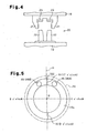
- spring holes 46 (only one is shown in Fig. 2) for accommodating the spring 27 are formed in the limiting surface 19c of the guiding member 19.
- the transverse cross section of the spring hole 46 is substantially circular.
- the axis of the circle of the hole 46 is parallel to the central axis M of the guiding member 19.
- TDC a portion on the swash plate 24 that corresponds to a top dead center
- An imaginary plate containing the top dead center portion TDC and the central axis M of the swash plate 24 is denoted as an imaginary plane H.
- One of the spring holes 46 is located in one of the areas of the swash plate 24 divided by the imaginary plane H (a right area as viewed in the drawing).
- the other spring hole 46 is located in the other area (left area as viewed in the drawing).
- the spring hole 46A and the spring hole 46B are symmetrical with respect to the imaginary plane H.
- the state of Fig. 5, or the state when the limiting surface 19c is viewed from the front, is regarded as a dial of a clock (in other words, the central axis M is regarded as the axis of a clock).
- Sections of lines at intersections of the annular limiting surface 19c and the imaginary plane H are referred to as line sections X1, X2.
- the line section X2, which is located at a side opposite from the top dead center portion TDC (lower side as viewed in the drawing), corresponds to six o'clock.
- the spring hole 46A (specifically the center of the opening of the spring hole 46A) is located in a range from twelve o' clock to three o' clock in the clockwise direction on the limiting surface 19c (preferably in a range from one o' clock to two o' clock).
- the spring hole 46B (specifically the center of the opening of the spring hole 46B) is located in a range from nine o'clock to twelve o'clock in the clockwise direction on the limiting surface 19c (preferably in a range from ten o'clock to eleven o' clock).
- the springs 27 accommodated in the spring holes 46A, 46B are arranged to apply force in a concentrated and intense manner to an area near the top dead center portion TDC on the swash plate 24 around the central axis M. At the area, the compression reaction force CS acts strongly.
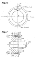
- a ball 47 which functions as bearing and a thrust bearing, is held by each of the spring holes 46A, 46B.
- Each ball 47 is urged toward the swash plate 24 by the force of the corresponding spring 27.
- Part of each ball 47 projects from the spring hole 46A, 46B, or from the limiting surface 19c, toward the swash plate 24.
- a roll groove 48 is formed to correspond to the limiting surface 19c of the guiding member 19.
- the roll groove 48 is formed annular around the central axis M.
- the transverse cross section of the roll groove 48 is substantially semicircular.
- each ball 47 which is urged by the corresponding spring 27, contacts the inner surface of the roll groove 48. That is, each spring 27 applies its force to the swash plate 24 through the corresponding ball 47 and the inner surface of the roll groove 48. Also, when the guiding member 19 and the swash plate 24 rotate relative to each other in the disengaged state of the clutch 26, the balls 47 roll on the inner surface of the roll groove 48 along the circumferential direction of the roll groove 48. That is, the balls 47 are located between the springs 27 and the swash plate 24, which rotates relative to the guiding member 19 in the disengaged state of the clutch 26.
- the swash plate 24 is moved by the force of the springs 27 to a position contacting the snap ring 25 against the compression reaction force CS, the clutch 26 is caused to the disengaged state.
- the swash plate 24 and the guiding member 19 rotate relative to each other. That is, the swash plate 24 slips on the guiding member 19, and the rotation speed of the swash plate 24 is lower than the rotation speed of the guiding member 19.
- the mechanical loss between the swash plate 24 and the shoes 31 is further reduced. Accordingly, the load of the compressor 10, which acts on the engine E, is further reduced.
- the swash plate 24 is slightly inclined relative to the axis L of the drive shaft 17, and the pistons 29 are reciprocated with a very small stroke. This causes refrigerant gas to be discharged to the discharge chamber 33 from the compression chambers 30.
- the refrigerant gas is then supplied to the crank chamber 16 from the discharge chamber 33 through the supply passage 39 and the control valve 40.
- the refrigerant gas in the crank chamber 16 is supplied to the suction chamber 32 through the bleed passage 38, and then drawn into the compression chambers 30 from the suction chamber 32. In this manner, when the compressor 10 is in the OFF operation, refrigerant gas circulates within the compressor 10 and passes through the control valve 40.
- the opening degree of the control valve 40 is less than the fully opened state (by starting the supply of electricity to the electromagnetic actuator 40a of the control valve 40), the flow rate of refrigerant gas supplied to the crank chamber 16 is decreased. Accordingly, the compression reaction force CS is relatively increased. Also, when the flow rate of refrigerant gas supplied to the crank chamber 16 decreases, the inclination angle of the swash plate 24 is increased, so that the displacement of the compressor 10 is increased from the minimum displacement (leaves the OFF operation and shifts to "an ON operation"). Therefore, the compression reaction force CS applied to the swash plate 24. is greater than the predetermined value. In this state, the compression reaction force CS acts dominantly to determine the position of the swash plate 24 relative to the guiding member 19 (the boss 19a) in a direction along the central axis M.
- the swash plate 24 is moved by the compression reaction force CS to a position where the driven clutch surface 26b contacts the driving clutch surface 26a against to the force of the springs 27. This engages the clutch 26, and the swash plate 24 and the guiding member 19 start rotate integrally. If the opening degree of the control valve 40 is changed in a state where the swash plate 24 and the guiding member 19 rotate integrally, that is, in the on operating state of the compressor 10, the inclination angle of the guiding member 19 and the swash plate 24 is changed.
- the clutch 26 may be directly controlled from the outside with dedicated means. That is, for example, the clutch 26 may be replaced by an electromagnetic friction clutch or an electromagnetic powder clutch. Alternatively, a dedicated actuator (for example, an electromagnetic actuator) may be used for sliding the swash plate 24. In these cases, the clutch 26 can be switched regardless of the displacement of the compressor 10, that is, the opening degree of the control valve 40.
- a disc spring or a wave spring may be used as the spring 27.
- the spring holes 46, the springs 27, and the balls 47 may be provided in the swash plate 24.
- additional sets of the spring holes 46, the springs 27, and the balls 47 may be provided in a range from three o' clock to nine o' clock along the clockwise direction.
- the spring holes 46, the springs 27, and the balls 47 may be provided only in a range from three o' clock to nine o' clock along the clockwise direction.
- the spring hole 46A and the spring hole 46B may be located at asymmetrical positions with respect to the imaginary plane H.
- the balls 47 may be omitted.
- the spring holes 46 may be omitted, and projections may be formed on the limiting surface 19c to support the springs 27.
- each spring 27 is fitted around a projection.
- a ball seat for holding the ball 47 is preferably formed on each spring 27.
- the spring holes 46, the springs 27, the balls 47, and the roll groove 48 may be omitted.
- a coil spring or an annular wave spring may be used as the spring 90.
- the spring 90 may be omitted.
- At least one of a surface of the snap ring 25 contacting the swash plate 24 and a surface of the swash plate 24 contacting the snap ring 25 may be coated (for example, with polytetrafluoroethylene) or plated (for example, with tin) to reduce the friction coefficient. In this configuration, mechanical loss between the swash plate 24 and the snap ring 25 when the clutch 26 is disengaged is reduced.
- At least one of the constant diameter portion 43a of the boss 19a and the constant diameter portion 41a of the boss receiving hole 24a may be coated (for example, with polytetrafluoroethylene) or plated (for example, with tin) to reduce the friction coefficient.
- the guiding member 19 and the swash plate 24 rotate relative to each other, that is, when the clutch 26 is in the disengaged state, the mechanical loss between the constant diameter portion 43a of the boss 19a and the constant diameter portion 41a of the boss receiving hole 24a is reduced. Further, when the clutch 26 is switched, the swash plate 24 is slid smoothly.
- surface of the guiding member 19 and the swash plate 24 that contact the spring 90 or both side surface of the spring 90 may be coated (for example, with polytetrafluoroethylene) or plated (for example, with tin) to reduce the friction coefficient.
- a thrust bearing may be provided in at least one of the space between the guiding member 19 and the spring 90 and the space between the swash plate 24 and the spring 90.
- two or more reservoir grooves 79 may be provided.
- two or more oil supply holes 78 may be provided.
- the reservoir groove 79 may be formed only on the outer circumferential surface 43 of the boss 19a.
- two reservoir grooves 79 may be provided. In this case, one of the grooves 79 is formed on the inner circumferential surface 41 of the boss receiving hole 24a, and the other groove 79 is formed on the outer circumferential surface 43 of the boss 19a.
- the reservoir groove 79 may be provided only in the constant diameter portion 41a. Alternatively, the reservoir groove 79 may be provided only on the driven clutch surface 26b.
- the reservoir groove 79 may be omitted.
- the configuration of the oil supply portion 77 may be changed to supply lubricant oil to the space between the guiding member 19 and the swash plate 24 without using centrifugal force.
- a pump that is actuated by rotation of the drive shaft 17 is provided, and by the action of the pump, lubricant oil is supplied to the space between the guiding member 19 and the swash plate 24.
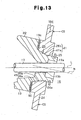
- the driving clutch surface 26a may formed on a part of the outer circumferential surface 43 of the boss 19a, and the driven clutch surface 26b may be formed on a part of the inner circumferential surface 41 of the boss receiving hole 24a.
- This modification has the advantage (10) of the compressor according to the first embodiment. In this case, the heights of the driving projections 92 and the driven projections 93 are preferably low.
- a spring may be provided between the guiding member 19 and the swash plate 24, so that, when the clutch 26 is switched from the engaged state to the disengaged state, the force of the spring is used to slide the swash plate 24.
- the oil supply portion 77 of the fifth embodiment may be used.
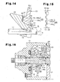
- the radial bearing of the third or fourth embodiment may be used.
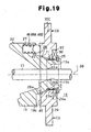
- the radial bearing of the third or fourth embodiment may be used as shown in Fig. 19.
- the present invention may be applied to a compressor other than the refrigerant compressor.
- the present invention may be applied to an air compressor.
Landscapes
- Engineering & Computer Science (AREA)
- General Engineering & Computer Science (AREA)
- Mechanical Engineering (AREA)
- Manufacturing & Machinery (AREA)
- Compressors, Vaccum Pumps And Other Relevant Systems (AREA)
Applications Claiming Priority (6)
| Application Number | Priority Date | Filing Date | Title |
|---|---|---|---|
| JP2003314795 | 2003-09-05 | ||
| JP2003314795 | 2003-09-05 | ||
| JP2004167738 | 2004-06-04 | ||
| JP2004167738 | 2004-06-04 | ||
| JP2004224709 | 2004-07-30 | ||
| JP2004224709A JP2006017097A (ja) | 2003-09-05 | 2004-07-30 | 斜板式可変容量圧縮機 |
Publications (1)
| Publication Number | Publication Date |
|---|---|
| EP1512870A1 true EP1512870A1 (de) | 2005-03-09 |
Family
ID=34139398
Family Applications (1)
| Application Number | Title | Priority Date | Filing Date |
|---|---|---|---|
| EP04021039A Withdrawn EP1512870A1 (de) | 2003-09-05 | 2004-09-03 | Schrägscheibenverdichter mit veränderlicher Fördermenge |
Country Status (5)
| Country | Link |
|---|---|
| US (1) | US20050058551A1 (de) |
| EP (1) | EP1512870A1 (de) |
| JP (1) | JP2006017097A (de) |
| KR (1) | KR100572546B1 (de) |
| CN (1) | CN1590765A (de) |
Families Citing this family (14)
| Publication number | Priority date | Publication date | Assignee | Title |
|---|---|---|---|---|
| US7250756B1 (en) | 2006-02-09 | 2007-07-31 | Timken Us Corporation | Flexible sensor input assembly |
| US20090232667A1 (en) * | 2006-07-12 | 2009-09-17 | Hugelman Rodney D | Axial compressor |
| US8763734B2 (en) * | 2007-04-05 | 2014-07-01 | Haldex Brake Corporation | Drive through air compressor with cone clutch |
| KR101280515B1 (ko) | 2007-06-04 | 2013-07-01 | 한라비스테온공조 주식회사 | 가변 용량형 사판식 압축기 |
| JP5371627B2 (ja) * | 2008-08-27 | 2013-12-18 | キヤノン株式会社 | 現像装置、現像カートリッジ、及び、電子写真画像形成装置 |
| US8584441B2 (en) | 2010-01-05 | 2013-11-19 | Honeywell International Inc. | Fuel metering system electrically servoed metering pump |
| JP5482821B2 (ja) | 2012-01-19 | 2014-05-07 | 株式会社豊田自動織機 | 斜板式可変容量型圧縮機及び斜板式可変容量型圧縮機におけるソレノイド制御方法 |
| KR20140097852A (ko) * | 2013-01-30 | 2014-08-07 | 한라비스테온공조 주식회사 | 사판식 압축기 |
| KR102582391B1 (ko) * | 2016-12-29 | 2023-09-26 | 한온시스템 주식회사 | 압축기 |
| US11143174B2 (en) | 2017-03-24 | 2021-10-12 | Hanon Systems | Compressor |
| RU2019142842A (ru) | 2017-06-27 | 2021-07-27 | СиДаблЮ Хлдингс, Лтд. | Насос с переменным ходом |
| CN108361165B (zh) * | 2018-04-09 | 2019-08-13 | 李涌权 | 容量可调型流体泵 |
| US10670003B1 (en) * | 2019-10-24 | 2020-06-02 | CW Holdings Ltd. | Tilt linkage for variable stroke pump |
| US12523202B2 (en) * | 2021-09-22 | 2026-01-13 | Koganei Corporation | Liquid supply device |
Citations (4)
| Publication number | Priority date | Publication date | Assignee | Title |
|---|---|---|---|---|
| GB1259623A (de) * | 1968-04-16 | 1972-01-05 | ||
| US5063829A (en) * | 1989-08-09 | 1991-11-12 | Hitachi, Ltd. | Variable displacement swash plate type compressor |
| EP0853198A2 (de) * | 1997-01-09 | 1998-07-15 | Sanden Corporation | Taumelscheibenverdichter mit verbesserter Verbindung zwischen Taumbelscheibe und Kolben |
| US6474183B1 (en) * | 1999-03-11 | 2002-11-05 | Sanden Corporation | Variable-displacement inclined plate compressor |
Family Cites Families (3)
| Publication number | Priority date | Publication date | Assignee | Title |
|---|---|---|---|---|
| US5380161A (en) * | 1992-12-11 | 1995-01-10 | Kabushiki Kaisha Toyoda Jidoshokki Seisakusho | Variable capacity swash-plate compressor with electromagnetic clutch |
| JP3254853B2 (ja) * | 1993-11-05 | 2002-02-12 | 株式会社豊田自動織機 | クラッチレス片側ピストン式可変容量圧縮機 |
| KR100245674B1 (ko) * | 1997-10-31 | 2000-04-01 | 정몽규 | 차량용 냉방장치 |
-
2004
- 2004-07-30 JP JP2004224709A patent/JP2006017097A/ja active Pending
- 2004-08-17 KR KR1020040064602A patent/KR100572546B1/ko not_active Expired - Fee Related
- 2004-09-03 US US10/933,553 patent/US20050058551A1/en not_active Abandoned
- 2004-09-03 EP EP04021039A patent/EP1512870A1/de not_active Withdrawn
- 2004-09-06 CN CNA2004100687496A patent/CN1590765A/zh active Pending
Patent Citations (4)
| Publication number | Priority date | Publication date | Assignee | Title |
|---|---|---|---|---|
| GB1259623A (de) * | 1968-04-16 | 1972-01-05 | ||
| US5063829A (en) * | 1989-08-09 | 1991-11-12 | Hitachi, Ltd. | Variable displacement swash plate type compressor |
| EP0853198A2 (de) * | 1997-01-09 | 1998-07-15 | Sanden Corporation | Taumelscheibenverdichter mit verbesserter Verbindung zwischen Taumbelscheibe und Kolben |
| US6474183B1 (en) * | 1999-03-11 | 2002-11-05 | Sanden Corporation | Variable-displacement inclined plate compressor |
Also Published As
| Publication number | Publication date |
|---|---|
| KR100572546B1 (ko) | 2006-04-24 |
| JP2006017097A (ja) | 2006-01-19 |
| US20050058551A1 (en) | 2005-03-17 |
| CN1590765A (zh) | 2005-03-09 |
| KR20050025268A (ko) | 2005-03-14 |
Similar Documents
| Publication | Publication Date | Title |
|---|---|---|
| EP0740076B1 (de) | Schiefscheibenverdichter mit veränderlicher Verdrängung | |
| EP1512870A1 (de) | Schrägscheibenverdichter mit veränderlicher Fördermenge | |
| EP0635640B1 (de) | Lageranordnung zur Verwendung in einem Kompressor | |
| EP0698735B1 (de) | Führungsmechanismus für Verdrängerkolben eines Kolbenverdichters | |
| EP1959137B1 (de) | Saugdrosselventil für einen Kompressor mit veränderlicher Verdrängung | |
| EP1167764A2 (de) | Taumelscheibenkompressor mit veränderlicher Förderleistung | |
| EP1394411B1 (de) | Taumelscheibenkompressor mit variabler Verdrängung | |
| US6283722B1 (en) | Variable displacement type compressor | |
| EP0857530A1 (de) | Verfahren zum Bearbeiten eines Kompressorenkolben | |
| JP4055410B2 (ja) | 容量可変型圧縮機の容量制御装置 | |
| EP1167759A1 (de) | Verdichter mit veränderlicher fördermenge | |
| US6076449A (en) | Variable displacement compressor | |
| US6544004B2 (en) | Single-headed piston type compressor | |
| EP0903495A2 (de) | Schiefscheibenkühlverdichter mit veränderlicher Förderleistung | |
| JP3932584B2 (ja) | 可変容量圧縮機 | |
| US20040055456A1 (en) | Variable displacement compressor | |
| US6546841B2 (en) | Swash plate compressor and piston therefor | |
| EP1070845A1 (de) | Mechanismus zur regelung desw kurbelgehäusedrucks bei kolbenkompressoren | |
| US5890878A (en) | Valve structure in compressor | |
| JP2755193B2 (ja) | 圧縮機におけるピストン | |
| US7320576B2 (en) | Clutchless variable displacement refrigerant compressor with mechanism for reducing displacement work at increased driven speed during non-operation of refrigerating system including the compressor | |
| KR20120018911A (ko) | 용량 가변형 사판식 압축기 | |
| US20040202551A1 (en) | Variable displacement compressor | |
| JPH1061548A (ja) | 可変容量圧縮機 | |
| US20010042438A1 (en) | Piston for swash plate type compressor |
Legal Events
| Date | Code | Title | Description |
|---|---|---|---|
| PUAI | Public reference made under article 153(3) epc to a published international application that has entered the european phase |
Free format text: ORIGINAL CODE: 0009012 |
|
| 17P | Request for examination filed |
Effective date: 20040903 |
|
| AK | Designated contracting states |
Kind code of ref document: A1 Designated state(s): AT BE BG CH CY CZ DE DK EE ES FI FR GB GR HU IE IT LI LU MC NL PL PT RO SE SI SK TR |
|
| AX | Request for extension of the european patent |
Extension state: AL HR LT LV MK |
|
| AKX | Designation fees paid |
Designated state(s): DE FR IT |
|
| GRAP | Despatch of communication of intention to grant a patent |
Free format text: ORIGINAL CODE: EPIDOSNIGR1 |
|
| STAA | Information on the status of an ep patent application or granted ep patent |
Free format text: STATUS: THE APPLICATION IS DEEMED TO BE WITHDRAWN |
|
| 18D | Application deemed to be withdrawn |
Effective date: 20060702 |