EP1512866A2 - Fuel injection pump having filter - Google Patents
Fuel injection pump having filter Download PDFInfo
- Publication number
- EP1512866A2 EP1512866A2 EP04018385A EP04018385A EP1512866A2 EP 1512866 A2 EP1512866 A2 EP 1512866A2 EP 04018385 A EP04018385 A EP 04018385A EP 04018385 A EP04018385 A EP 04018385A EP 1512866 A2 EP1512866 A2 EP 1512866A2
- Authority
- EP
- European Patent Office
- Prior art keywords
- fuel
- pressure
- housing
- low
- pressurizing chamber
- Prior art date
- Legal status (The legal status is an assumption and is not a legal conclusion. Google has not performed a legal analysis and makes no representation as to the accuracy of the status listed.)
- Granted
Links
- 239000000446 fuel Substances 0.000 title claims abstract description 622
- 238000002347 injection Methods 0.000 title claims abstract description 80
- 239000007924 injection Substances 0.000 title claims abstract description 80
- 230000033001 locomotion Effects 0.000 claims description 16
- 238000002485 combustion reaction Methods 0.000 claims description 10
- 238000003780 insertion Methods 0.000 claims description 2
- 230000037431 insertion Effects 0.000 claims description 2
- 238000004140 cleaning Methods 0.000 description 22
- 230000000694 effects Effects 0.000 description 11
- 230000004308 accommodation Effects 0.000 description 10
- 238000003860 storage Methods 0.000 description 8
- 238000007599 discharging Methods 0.000 description 7
- 239000002828 fuel tank Substances 0.000 description 7
- 238000007789 sealing Methods 0.000 description 7
- 238000005461 lubrication Methods 0.000 description 6
- 238000004519 manufacturing process Methods 0.000 description 6
- 230000002093 peripheral effect Effects 0.000 description 5
- XAGFODPZIPBFFR-UHFFFAOYSA-N aluminium Chemical compound [Al] XAGFODPZIPBFFR-UHFFFAOYSA-N 0.000 description 3
- 229910052782 aluminium Inorganic materials 0.000 description 3
- 239000007769 metal material Substances 0.000 description 3
- 238000011144 upstream manufacturing Methods 0.000 description 3
- 230000002159 abnormal effect Effects 0.000 description 2
- 238000009825 accumulation Methods 0.000 description 2
- 230000002950 deficient Effects 0.000 description 2
- 210000002445 nipple Anatomy 0.000 description 2
- 230000000717 retained effect Effects 0.000 description 2
- 239000010935 stainless steel Substances 0.000 description 2
- 229910001220 stainless steel Inorganic materials 0.000 description 2
- 229910000838 Al alloy Inorganic materials 0.000 description 1
- 238000005299 abrasion Methods 0.000 description 1
- 230000000903 blocking effect Effects 0.000 description 1
- 229910010293 ceramic material Inorganic materials 0.000 description 1
- 238000004891 communication Methods 0.000 description 1
- 238000005516 engineering process Methods 0.000 description 1
- 239000012535 impurity Substances 0.000 description 1
- 230000002401 inhibitory effect Effects 0.000 description 1
- 230000001050 lubricating effect Effects 0.000 description 1
- 238000000034 method Methods 0.000 description 1
- 238000012986 modification Methods 0.000 description 1
- 230000004048 modification Effects 0.000 description 1
- 238000000465 moulding Methods 0.000 description 1
- 230000000149 penetrating effect Effects 0.000 description 1
- 230000035515 penetration Effects 0.000 description 1
- 238000003825 pressing Methods 0.000 description 1
Images


Classifications
-
- F—MECHANICAL ENGINEERING; LIGHTING; HEATING; WEAPONS; BLASTING
- F02—COMBUSTION ENGINES; HOT-GAS OR COMBUSTION-PRODUCT ENGINE PLANTS
- F02M—SUPPLYING COMBUSTION ENGINES IN GENERAL WITH COMBUSTIBLE MIXTURES OR CONSTITUENTS THEREOF
- F02M37/00—Apparatus or systems for feeding liquid fuel from storage containers to carburettors or fuel-injection apparatus; Arrangements for purifying liquid fuel specially adapted for, or arranged on, internal-combustion engines
- F02M37/04—Feeding by means of driven pumps
- F02M37/043—Arrangements for driving reciprocating piston-type pumps
-
- F—MECHANICAL ENGINEERING; LIGHTING; HEATING; WEAPONS; BLASTING
- F02—COMBUSTION ENGINES; HOT-GAS OR COMBUSTION-PRODUCT ENGINE PLANTS
- F02M—SUPPLYING COMBUSTION ENGINES IN GENERAL WITH COMBUSTIBLE MIXTURES OR CONSTITUENTS THEREOF
- F02M37/00—Apparatus or systems for feeding liquid fuel from storage containers to carburettors or fuel-injection apparatus; Arrangements for purifying liquid fuel specially adapted for, or arranged on, internal-combustion engines
- F02M37/22—Arrangements for purifying liquid fuel specially adapted for, or arranged on, internal-combustion engines, e.g. arrangements in the feeding system
- F02M37/32—Arrangements for purifying liquid fuel specially adapted for, or arranged on, internal-combustion engines, e.g. arrangements in the feeding system characterised by filters or filter arrangements
- F02M37/34—Arrangements for purifying liquid fuel specially adapted for, or arranged on, internal-combustion engines, e.g. arrangements in the feeding system characterised by filters or filter arrangements by the filter structure, e.g. honeycomb, mesh or fibrous
-
- F—MECHANICAL ENGINEERING; LIGHTING; HEATING; WEAPONS; BLASTING
- F02—COMBUSTION ENGINES; HOT-GAS OR COMBUSTION-PRODUCT ENGINE PLANTS
- F02M—SUPPLYING COMBUSTION ENGINES IN GENERAL WITH COMBUSTIBLE MIXTURES OR CONSTITUENTS THEREOF
- F02M37/00—Apparatus or systems for feeding liquid fuel from storage containers to carburettors or fuel-injection apparatus; Arrangements for purifying liquid fuel specially adapted for, or arranged on, internal-combustion engines
- F02M37/22—Arrangements for purifying liquid fuel specially adapted for, or arranged on, internal-combustion engines, e.g. arrangements in the feeding system
- F02M37/32—Arrangements for purifying liquid fuel specially adapted for, or arranged on, internal-combustion engines, e.g. arrangements in the feeding system characterised by filters or filter arrangements
- F02M37/44—Filters structurally associated with pumps
-
- F—MECHANICAL ENGINEERING; LIGHTING; HEATING; WEAPONS; BLASTING
- F02—COMBUSTION ENGINES; HOT-GAS OR COMBUSTION-PRODUCT ENGINE PLANTS
- F02M—SUPPLYING COMBUSTION ENGINES IN GENERAL WITH COMBUSTIBLE MIXTURES OR CONSTITUENTS THEREOF
- F02M37/00—Apparatus or systems for feeding liquid fuel from storage containers to carburettors or fuel-injection apparatus; Arrangements for purifying liquid fuel specially adapted for, or arranged on, internal-combustion engines
- F02M37/22—Arrangements for purifying liquid fuel specially adapted for, or arranged on, internal-combustion engines, e.g. arrangements in the feeding system
- F02M37/32—Arrangements for purifying liquid fuel specially adapted for, or arranged on, internal-combustion engines, e.g. arrangements in the feeding system characterised by filters or filter arrangements
- F02M37/46—Filters structurally associated with pressure regulators
-
- F—MECHANICAL ENGINEERING; LIGHTING; HEATING; WEAPONS; BLASTING
- F02—COMBUSTION ENGINES; HOT-GAS OR COMBUSTION-PRODUCT ENGINE PLANTS
- F02M—SUPPLYING COMBUSTION ENGINES IN GENERAL WITH COMBUSTIBLE MIXTURES OR CONSTITUENTS THEREOF
- F02M37/00—Apparatus or systems for feeding liquid fuel from storage containers to carburettors or fuel-injection apparatus; Arrangements for purifying liquid fuel specially adapted for, or arranged on, internal-combustion engines
- F02M37/22—Arrangements for purifying liquid fuel specially adapted for, or arranged on, internal-combustion engines, e.g. arrangements in the feeding system
- F02M37/32—Arrangements for purifying liquid fuel specially adapted for, or arranged on, internal-combustion engines, e.g. arrangements in the feeding system characterised by filters or filter arrangements
- F02M37/48—Filters structurally associated with fuel valves
-
- F—MECHANICAL ENGINEERING; LIGHTING; HEATING; WEAPONS; BLASTING
- F02—COMBUSTION ENGINES; HOT-GAS OR COMBUSTION-PRODUCT ENGINE PLANTS
- F02M—SUPPLYING COMBUSTION ENGINES IN GENERAL WITH COMBUSTIBLE MIXTURES OR CONSTITUENTS THEREOF
- F02M59/00—Pumps specially adapted for fuel-injection and not provided for in groups F02M39/00 -F02M57/00, e.g. rotary cylinder-block type of pumps
- F02M59/02—Pumps specially adapted for fuel-injection and not provided for in groups F02M39/00 -F02M57/00, e.g. rotary cylinder-block type of pumps of reciprocating-piston or reciprocating-cylinder type
- F02M59/04—Pumps specially adapted for fuel-injection and not provided for in groups F02M39/00 -F02M57/00, e.g. rotary cylinder-block type of pumps of reciprocating-piston or reciprocating-cylinder type characterised by special arrangement of cylinders with respect to piston-driving shaft, e.g. arranged parallel to that shaft or swash-plate type pumps
- F02M59/06—Pumps specially adapted for fuel-injection and not provided for in groups F02M39/00 -F02M57/00, e.g. rotary cylinder-block type of pumps of reciprocating-piston or reciprocating-cylinder type characterised by special arrangement of cylinders with respect to piston-driving shaft, e.g. arranged parallel to that shaft or swash-plate type pumps with cylinders arranged radially to driving shaft, e.g. in V or star arrangement
-
- F—MECHANICAL ENGINEERING; LIGHTING; HEATING; WEAPONS; BLASTING
- F02—COMBUSTION ENGINES; HOT-GAS OR COMBUSTION-PRODUCT ENGINE PLANTS
- F02M—SUPPLYING COMBUSTION ENGINES IN GENERAL WITH COMBUSTIBLE MIXTURES OR CONSTITUENTS THEREOF
- F02M59/00—Pumps specially adapted for fuel-injection and not provided for in groups F02M39/00 -F02M57/00, e.g. rotary cylinder-block type of pumps
- F02M59/20—Varying fuel delivery in quantity or timing
- F02M59/36—Varying fuel delivery in quantity or timing by variably-timed valves controlling fuel passages to pumping elements or overflow passages
- F02M59/366—Valves being actuated electrically
-
- F—MECHANICAL ENGINEERING; LIGHTING; HEATING; WEAPONS; BLASTING
- F02—COMBUSTION ENGINES; HOT-GAS OR COMBUSTION-PRODUCT ENGINE PLANTS
- F02M—SUPPLYING COMBUSTION ENGINES IN GENERAL WITH COMBUSTIBLE MIXTURES OR CONSTITUENTS THEREOF
- F02M59/00—Pumps specially adapted for fuel-injection and not provided for in groups F02M39/00 -F02M57/00, e.g. rotary cylinder-block type of pumps
- F02M59/44—Details, components parts, or accessories not provided for in, or of interest apart from, the apparatus of groups F02M59/02 - F02M59/42; Pumps having transducers, e.g. to measure displacement of pump rack or piston
Definitions
- a fuel filter 13 is disposed in the fuel supply passage 10.
- the fuel filter 13 filters or traps impurities in the fuel drawn from the fuel tank 9 into the feed pump 12.
- the fuel sump chamber 17a is a space provided by an accommodation hole 17 of the suction quantity control electromagnetic valve 5 formed in the housing 30 and the tip end portion (the left end in Fig. 1) of the suction quantity control electromagnetic valve 5 accommodated in the accommodation hole 17.
- the accommodation hole 17 is a stepped hole having a bottom.
- the accommodation hole 17 is provided by a hole portion with the bottom having substantially the same internal diameter as a valve housing 21 explained after, and a control fuel storage portion, whose internal diameter is larger than the hole portion.
- a space defined by the valve housing 21 and the control fuel storage portion provides a control fuel (low-pressure fuel) storage chamber 17b.
- the first housing portion 30a is formed with the fuel leading passage 16a, the fuel sump chamber 17a, the control fuel storage chamber 17b and the control fuel passage 16b of the low-pressure fuel passage formed in the housing 30.
- the first housing portion 30a is formed with the fuel lubrication passage 12r out of the fuel suction passage 12h, 15 and the return fuel passage 12r, 50.
- Stepped portions 16ad continuing to the fitting holes 83 are formed on the upper end surface and the lower end surface of the first housing portion 30a in Fig. 1, and sealing members 91 such as O rings are disposed on the stepped portions 16ad as shown in Fig. 2 so that the first housing portion 30a and the second housing portions 33, 34 can hold the fluid-tightness.
- the plate members 46, 47 reciprocate on the upper and lower end surfaces of the cam ring 45 in Fig. 1.
- the first and second plungers 41, 42 reciprocate inside the sliding holes 33a, 34a in the vertical direction in Fig. 1.
- the first and second plungers 41, 42 pressurize the fuel in the first and second pressurizing chambers 51, 52 and pressure-feed the high-pressure fuel. More specifically, if the first plunger 41 moves from a top dead center to a bottom dead center in the sliding hole 33a in a suction stroke, the low-pressure fuel discharged from the feed pump 12 opens the first suction valve 31 and flows into the first fuel pressurizing chamber 51.
- the filter 81 may be disposed in a fuel passage leading from the inlet portion of the fourth low-pressure fuel passage 420 to the fuel pressurizing chamber 51 in the fourth low-pressure fuel passage 420, instead of disposing the filter 81 in the inlet portion of the fourth low-pressure fuel passage 420.
- the metallic mesh portion 81a may be formed of a stainless-steel metallic mesh, or may be formed of porous ceramic material.
- the fuel injection pump according to the first or second embodiment includes the two plungers, and the fuel injection pump according to the third, fourth or fifth embodiment includes the three plungers.
- a similar effect can be obtained by applying the present invention to any type of fuel injection pump having multiple plungers.
Landscapes
- Engineering & Computer Science (AREA)
- Chemical & Material Sciences (AREA)
- Combustion & Propulsion (AREA)
- Mechanical Engineering (AREA)
- General Engineering & Computer Science (AREA)
- Fuel-Injection Apparatus (AREA)
- Details Of Reciprocating Pumps (AREA)
- Reciprocating Pumps (AREA)
Abstract
Description
- The present invention relates to a fuel injection pump. For instance, the present invention can be suitably applied to a fuel injection pump used in an accumulation type fuel injection system of a diesel engine.
- There is a fuel injection pump having a camshaft, a cam ring and at least one plunger, for instance, as disclosed in Unexamined Japanese Patent Application Publication No. 2002-364480 (Patent Document 1, hereafter) or No. 2002-250459 (
Patent Document 2, hereafter). The camshaft has a cam, which has a circular section, thereon. The cam ring is rotatably fitted to an outer periphery of the cam through a bush. The plunger is held inside a cylinder so that the plunger can reciprocate in the cylinder. If an engine drives the camshaft to rotate, the rotational movement of the cam is transmitted to the plunger through the cam ring. Thus, the plunger reciprocates inside the cylinder and pressure-feeds the fuel. The fuel injection pump has two fuel pressurizing chambers, which are alternately pressurized by the two reciprocating plungers. The fuel injection pump has discharge valves for alternately discharging the fuel pressurized in the fuel pressurizing chambers. - There is a possibility that extraneous matters are mixed into the fuel and get stuck between operating members, which perform rotational movement, reciprocating movement, and the like.
- The fuel injection pump disclosed in Patent Document 1 includes a rotary pump for supplying low-pressure fuel into the fuel pressurizing chamber. An inner rotor of the rotary pump is screwed to the camshaft at a predetermined torque .through a bolt having a lead directed in the same direction as the rotation direction of the camshaft. If the extraneous matters in the fuel get stuck between gears of the inner rotor and an outer rotor, an abnormal turning force will be generated in the camshaft. In this case, the abnormal turning force will overmatch a force fastening the bolt, and the bolt will be loosened. As a result, the camshaft and the inner rotor are uncoupled.
- The fuel injection pump disclosed in
Patent Document 2 includes a suction quantity control electromagnetic valve for supplying the fuel into the fuel pressurizing chamber and for controlling the quantity of the fuel pressurized and pressure-fed by the plunger. A valve member and an armature of the suction quantity control electromagnetic valve are formed with penetration passages axially penetrating the valve member and the armature. The suction quantity control electromagnetic valve is formed with a communication passage for connecting an upstream passage of control fuel with an armature chamber. Since a flow of the fuel is generated in the armature chamber, the fuel will not stay around the armature. Therefore, even if the extraneous matters included in the fuel exist in the armature chamber, the extraneous matters will be discharged outward along the flow of the fuel. - Usually, a filter is attached to a fuel inlet portion of the fuel injection pump in order to prevent the entry of the extraneous matters in the fuel from the outside.
- The conventional technology can prevent defective operations or damages caused by the extraneous matters included in the fuel but cannot eliminate the extraneous matters sufficiently. The filter disposed in the fuel inlet portion of the fuel injection pump alone cannot sufficiently eliminate the extraneous matters, which can cause the defective operations or the damages.
- There is a possibility that the extraneous matters such as burrs or chips generated during the manufacturing of components of the fuel injection pump remain inside. Therefore, the remaining extraneous matters are eliminated through cleaning and the like after the manufacturing. However, a housing has relatively complicated fuel passages among the components. Therefore, actually, there is a possibility that the extraneous matters remain in the fuel passages of the housing because of insufficient cleaning in high-pressure cleaning and the like performed after the manufacturing.
- If the extraneous matters remaining because of the insufficient cleaning get stuck in a seat portion of a suction valve or a discharge valve as an operating member, fluid-tightness of the seat portion cannot be maintained and an appropriate fuel pressure-feeding quantity (a discharging quantity) cannot be obtained. If the extraneous matters get stuck in the seat portion of one of the discharge valves, which alternately discharge the fuel pressurized in the two fuel pressurizing chambers, and if the discharge valve is brought to a continuously opened state, the high pressure of the pressurized fuel is continuously applied to the plunger. As a result, poor lubrication will be caused between the plunger and a plunger sliding hole and seizing in the plunger will be caused. If the high pressure is continuously applied to the plunger, an excessive thrust force is applied to the cam ring. In this case, there is a possibility that the plunger breaks.
- Moreover, in the case where the fraction produced when the plunger breaks moves inside a cam chamber and gets stuck between the housing and the cam ring, the housing will be damaged if the housing is made of aluminum.
- It is therefore an object of the present invention to eliminate extraneous matters remaining in a fuel injection pump.
- It is another object of the present invention to provide a fuel injection pump capable of inhibiting troubles caused by extraneous matters remaining inside.
- According to an aspect of the present invention, a fuel injection pump includes a camshaft driven by an internal combustion engine to rotate, a cam rotating with the camshaft, a cam ring revolving around the camshaft so that the cam ring can rotate with respect to the cam along an outer periphery of the cam, a housing for rotatably housing the camshaft, the housing having a fuel pressurizing chamber, a plunger for pressurizing and pressure-feeding fuel, which is drawn into the fuel pressurizing chamber, by reciprocating in accordance with the revolution of the cam ring, and a rotary pump rotated by the camshaft for supplying the fuel, which is drawn into the fuel pressurizing chamber. The housing has a first housing portion for rotatably housing the camshaft, the cam ring and the rotary pump, and a second housing portion for housing the plunger so that the plunger can reciprocate. The first housing portion is formed with a first low-pressure fuel passage for streaming low-pressure fuel from the rotary pump toward the fuel pressurizing chamber. The second housing portion is formed with a second low-pressure fuel passage connected to the fuel pressurizing chamber. The fuel injection pump has a filter disposed in one of an outlet portion of the first low-pressure fuel passage, an inlet portion of the second low-pressure fuel passage facing the outlet portion of the first low-pressure fuel passage, and a certain point in the second low-pressure fuel passage.
- In the above structure, even in the case where the extraneous matters remain in the low-pressure fuel passage of the housing because of the insufficient cleaning in the high-pressure cleaning and the like, the extraneous matters can be trapped with the filter. Therefore, the extraneous matters, which can enter the fuel pressurizing chamber pressurizing and pressure-feeding the fuel through the movement of the plunger, are eliminated.
- Features and advantages of embodiments will be appreciated, as well as methods of operation and the function of the related parts, from a study of the following detailed description, the appended claims, and the drawings, all of which form a part of this application. In the drawings:
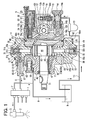
- Fig. 1 is a partially-sectional view showing a common rail type fuel injection system including a fuel injection pump according to a first embodiment of the present invention;
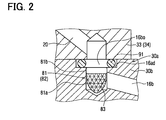
- Fig. 2 is an enlarged fragmentary sectional view showing a neighborhood of a low-pressure fuel passage of the fuel injection pump according to the first embodiment;
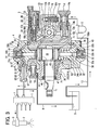
- Fig. 3 is a partially-sectional view showing a common rail type fuel injection system including a fuel injection pump according to a second embodiment of the present invention;
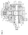
- Fig. 4 is a longitudinal sectional view showing a fuel injection pump according to a third embodiment of the present invention;
- Fig. 5A is a longitudinal sectional view showing a fuel injection pump according to a fourth embodiment of the present invention;
- Fig. 5B is a sectional view showing the fuel injection pump of Fig. 5A taken along the line VB-VB;
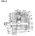
- Fig. 6 is a longitudinal sectional view showing a fuel injection pump according to a fifth embodiment of the present invention;
- Fig. 7A is an enlarged fragmentary sectional view showing a filter incorporated in a fuel injection pump of a modified example of the present invention; and
- Fig. 7B is an enlarged fragmentary sectional view showing a filter incorporated in the fuel injection pump of the modified example of the present invention.
-
- Referring to Fig. 1, a common rail type fuel injection system (a pressure accumulation type fuel injection system) including a
fuel injection pump 4 according to a first embodiment of the present invention is illustrated. - The common rail type fuel injection system shown in Fig. 1 is used in an internal combustion engine such as a multicylinder (four-cylinder, in Fig. 1) diesel engine. The fuel injection system accumulates high-pressure fuel in a common rail 1 and injects the accumulated high-pressure fuel into combustion chambers of respective cylinders of the engine through multiple injectors (electromagnetic fuel injection valves) 2 mounted in accordance with the respective cylinders of the engine. In Fig. 1, only one
injector 2 corresponding to one of the cylinders of the four-cylinder engine is illustrated. - The common rail type fuel injection system includes the common rail 1, the
multiple injectors 2, the fuel injection pump (the supply pump) 4 and a control device (an electronic control unit, or an ECU) as controlling means. The common rail 1 accumulates the high-pressure fuel. Theinjectors 2 are mounted on the respective cylinders of the engine and inject the high-pressure fuel accumulated in the common rail 1 into the combustion chambers of the respective cylinders. Thesupply pump 4 pressurizes the fuel and supplies the fuel toward the common rail 1. The ECU controls a valve opening operation and a valve closing operation of the multiple injectors 2 (more specifically, electromagnetic valves 3) and the supply pump 4 (more specifically, a suction quantity control electromagnetic valve 5), for instance. - In order to continuously accumulate the fuel in the common rail 1 at a high pressure corresponding to a fuel injection pressure, the high-pressure fuel is pressure-fed from the
supply pump 4 into the common rail 1 through a high-pressure fuel pipe 6. A fuel pressure sensor and a pressure limiter 7 are mounted to the common rail 1. The fuel pressure sensor senses the fuel pressure in the common rail 1 (a common rail pressure). If the common rail pressure exceeds a limit set pressure, the pressure limiter 7 opens in order to limit the common rail pressure below the limit set pressure. - The fuel injection from the
injector 2 into the combustion chamber is controlled by energizing and de-energizing the electromagnetic valve 3. The electromagnetic valve 3 controls the fuel pressure in a back pressure control chamber, which drives a command piston moving with a nozzle needle. More specifically, while the electromagnetic valve 3 of theinjector 2 is energized and the nozzle needle is opened, the high-pressure fuel accumulated in the common rail 1 is supplied into the combustion chamber of each cylinder through the injection. Thus, the engine is operated. - Surplus fuel such as leak fuel from a high-pressure fuel system including the
injectors 2, thesupply pump 4 and the pressure limiter 7 is returned to afuel tank 9 through afuel return pipe 8. - Next, a structure of the
supply pump 4 will be explained based on Figs. 1 and 2. As shown in Fig. 1, thesupply pump 4 includes acamshaft 11 as a pump drive shaft, acam 44 rotating with thecamshaft 11, acam ring 45 revolving around thecamshaft 11 along an outer periphery of thecam 44, first andsecond plungers rotary pump 12, the suction quantity controlelectromagnetic valve 5 as a control valve,check valves second suction valves discharge valves 61 and ahousing 30, in which the above components are housed or mounted. - As shown in Fig. 1, the
camshaft 11 as the pump drive shaft rotated by the engine is rotatably held in thehousing 30. A drive pulley is attached to an outer periphery of a tip end (the left end in Fig. 1) of thecamshaft 11. The drive pulley is linked with a crank pulley of a crankshaft of the engine through a driving force transmitting member such as a belt and is driven. A rotary pump (a feed pump) 12 for supplying the low-pressure fuel is connected to the other tip end (the right end in Fig.1) of thecamshaft 11. Thefeed pump 12 rotates integrally with thecamshaft 11 and draws the fuel from thefuel tank 9 through afuel supply passage 10. In Fig. 1, thefeed pump 12 is illustrated in a state in which thefeed pump 12 is rotated by an angle of 90°. Thefeed pump 12 may have any type of pump structure such as a vane type pump structure, instead of the inner gear type pump structure shown in Fig. 1. The innergear type pump 12 includes aninner rotor 12a, which is fitted to thecamshaft 11 with a clearance, and anouter rotor 12b, which is driven by theinner rotor 12a in sun-and-planet motion. - A
fuel filter 13 is disposed in thefuel supply passage 10. Thefuel filter 13 filters or traps impurities in the fuel drawn from thefuel tank 9 into thefeed pump 12. - As shown in Fig. 1, an inlet (a fuel inlet portion) 14 and a
fuel introduction passage 15 are formed on a suction side of thefeed pump 12. Theinlet 14 includes a sleeve nipple and a screw and introduces the fuel into thehousing 30 from the outside. Thefuel introduction passage 15 connects theinlet 14 with thefeed pump 12. Theinlet 14 incorporates a filter (a suction portion filter) 14a as shown in Fig. 1. A discharge side of thefeed pump 12 is connected with the suction quantity control electromagnetic valve 5 (more specifically, a fuel sump chamber 17a on the tip end side of the suction quantity control electromagnetic valve 5) through afuel leading passage 16a. The fuel sump chamber 17a is a space provided by an accommodation hole 17 of the suction quantity controlelectromagnetic valve 5 formed in thehousing 30 and the tip end portion (the left end in Fig. 1) of the suction quantity controlelectromagnetic valve 5 accommodated in the accommodation hole 17. The accommodation hole 17 is a stepped hole having a bottom. The accommodation hole 17 is provided by a hole portion with the bottom having substantially the same internal diameter as a valve housing 21 explained after, and a control fuel storage portion, whose internal diameter is larger than the hole portion. A space defined by the valve housing 21 and the control fuel storage portion provides a control fuel (low-pressure fuel)storage chamber 17b. - A mesh size of the
suction portion filter 14a of theinlet 14 should be preferably smaller than that of thefuel filter 13. Thefuel introduction passage 15 is formed with asuction hole 14b on theinlet 14 side. Theinlet 14 can be connected to thesuction hole 14b through screwing and the like. - The
inlet 14 and the fuel introduction passage 15 (more specifically, thesuction hole 14b) provide a suction portion for introducing the fuel from the outside. Thesuction portion filter 14a is incorporated by theinlet 14. Alternatively, thesuction portion filter 14a may be disposed in thesuction hole 14b or in thefuel introduction passage 15 if thesuction portion filter 14a is disposed inside the suction portion, which introduces the fuel from the outside. - A pressure regulation valve (a regulation valve) 18 is disposed near the
feed pump 12 as shown in Fig. 1. Theregulation valve 18 prevents the discharging pressure of the low-pressure fuel discharged from thefeed pump 12 into the fuel sump chamber 17a of the suction quantity controlelectromagnetic valve 5 from exceeding a predetermined fuel pressure. - The suction quantity control
electromagnetic valve 5 is a normally-open type electromagnetic flow control valve as shown in Fig. 1. The suction quantity controlelectromagnetic valve 5 has a valve member (a valve) 22, which is slidably held inside a sleeve-shaped valve housing 21, anelectromagnetic driving portion 23 as valve driving means for driving thevalve 22 in a valve closing direction, and acoil spring 24 as valve biasing means for biasing thevalve 22 in a valve opening direction. When energized, theelectromagnetic driving portion 23 generates an electromagnetic force and attracts a movable member (an armature) 26, which moves with thevalve 22. Thevalve 22 is opened by the biasing force of thecoil spring 24 when theelectromagnetic driving portion 23 is de-energized. If theelectromagnetic driving portion 23 is energized, thevalve 22 opens against the biasing force of thecoil spring 24. Thevalve 22 and the valve housing 21 provide a valve portion for performing valve opening operation and valve closing operation. - Instead of the electromagnetic flow control valve shown in Fig. 1, the suction quantity control
electromagnetic valve 5 may be any type of electromagnetic valve if the suction quantity controlelectromagnetic valve 5 has thevalve portion 21, 22 for streaming or blocking the control fuel, and theelectromagnetic driving portion 23 for driving thevalve portion 21, 22 to perform the valve opening operation and the valve closing operation. The clearance between thevalve 22 and the valve housing 21 and an armature chamber accommodating thearmature 26 of theelectromagnetic driving portion 23 should be preferably formed so that the fuel flows through the clearance and the armature chamber without staying there. - As shown in Fig. 1, surplus fuel, which is generated when the suction quantity control
electromagnetic valve 5 controls the flow of the fuel, is returned to the suction side of thefeed pump 12 through afuel return passage 12h connected to the suction quantity controlelectromagnetic valve 5, and thefuel introduction passage 15. Part of the fuel discharged from thefeed pump 12 is introduced into thecam chamber 5 through afuel lubrication passage 12r connected to thefeed pump 12 and lubricates various sliding portions such as theplungers supply pump 4 through an outlet (a fuel outlet portion) 19, which is provided by a sleeve nipple and a screw. The fuel flowing out of theoutlet 19 is returned to thefuel tank 9 through thefuel return passage 8. Thefuel return passage 12h and thefuel introduction passage 15 constitute a fuel suction passage for introducing the fuel into thefeed pump 12. Thefuel lubrication passage 12r and thecam chamber 50 constitute a return fuel passage for lubricating the various sliding portions of the various operating members and for returning the surplus fuel. - As shown in Fig. 1, the control fuel (the low-pressure fuel) controlled by the suction quantity control
electromagnetic valve 5 flows out to the controlfuel storage chamber 17b. The low-pressure fuel is drawn into multiplefuel pressurizing chambers fuel passages 16b and themultiple suction valves fuel storage chamber 17b communicates with thecontrol fuel passage 16b and thefuel suction passage 20 in that order. Thefuel suction passage 20 communicates with one of thesuction valves fuel pressurizing chambers plungers suction valves control fuel passages 16b or thefuel suction passages 20 is set in accordance with the number of thefuel pressurizing chambers 51, 52 (more specifically, the number of theplungers 41, 42). - The
first suction valve 31 and the firstfuel pressurizing chamber 51 correspond to thefirst plunger 41. Thesecond suction valve 32 and the secondfuel pressurizing chamber 52 correspond to thesecond plunger 42. - The
fuel leading passage 16a, the fuel sump chamber 17a, the controlfuel storage chamber 17b, thecontrol fuel passage 16b and thefuel suction passage 20 constitute the low-pressure fuel passage. The suction quantity controlelectromagnetic valve 5 is disposed in the low-pressure fuel passage. - The
first suction valve 31 is a check valve, whose forward direction coincides with the flow direction of the fuel flowing from thefeed pump 12 toward the firstfuel pressurizing chamber 51. Thefirst suction valve 31 includes avalve member 31a and acoil spring 31c as biasing means for biasing thevalve member 31a in a direction for seating thevalve member 31a on avalve seat 31b. Thefirst suction valve 31 functions as a check valve for preventing backflow of the fuel from the firstfuel pressurizing chamber 51 toward the suction quantity controlelectromagnetic valve 5. In a normal state, thefirst valve member 31a is biased by the biasing force of thecoil spring 31c upward in Fig. 1 and is seated on thevalve seat 31b. Thus, thefirst suction valve 31 is closed. If the low-pressure fuel flows in from the suction quantity controlelectromagnetic valve 5 through thefuel suction passage 20, the fuel pressure of the low-pressure fuel opens thefirst valve member 31a and the fuel is drawn into the firstfuel pressurizing chamber 51. If thefirst plunger 41 moves and pressurizes the fuel in the firstfuel pressurizing chamber 51, thevalve member 31a of thefirst suction valve 31 is closed by the fuel pressure in the firstfuel pressurizing chamber 51, and the state is retained until the_pressure-feeding of the fuel is finished. - Likewise, the
second suction valve 32 is a check valve, whose forward direction coincides with the flow direction of the fuel flowing from thefeed pump 12 toward the secondfuel pressurizing chamber 52. Thesecond suction valve 32 includes avalve member 32a and acoil spring 32c as biasing means for biasing thevalve member 32a in a direction for seating thevalve member 32a on avalve seat 32b. Thesecond suction valve 32 functions as a check valve for preventing backflow of the fuel from the secondfuel pressurizing chamber 52 toward the suction quantity controlelectromagnetic valve 5. In a normal state, thevalve member 32a is biased by the biasing force of thecoil spring 32c downward in Fig. 1 and is seated on thevalve seat 32b. If the low-pressure fuel flows in from the suction quantity controlelectromagnetic valve 5 through thefuel suction passage 20, the fuel pressure of the low-pressure fuel opens thevalve member 32a and the fuel is drawn into the secondfuel pressurizing chamber 52. If thesecond plunger 42 moves and pressurizes the fuel in the secondfuel pressurizing chamber 52, thevalve member 32a of thesecond suction valve 32 is closed by the fuel pressure in the secondfuel pressurizing chamber 52, and the state is retained until the pressure-feeding of the fuel is finished. - In the present embodiment, the
first suction valve 31 is disposed short of the firstfuel pressurizing chamber 51 in the low-pressure fuel passage. More specifically, thefirst suction valve 31 is disposed at a point where thefirst suction valve 31 and thefirst plunger 41 define the firstfuel pressurizing chamber 51. Instead, thefirst suction valve 31 may be disposed in thefuel suction passage 20 connected to the firstfuel pressurizing chamber 51. - The
second suction valve 32 is disposed short of the secondfuel pressurizing chamber 52 in the low-pressure fuel passage. More specifically, thesecond suction valve 32 is disposed at a point where thesecond suction valve 32 and thesecond plunger 42 define the secondfuel pressurizing chamber 52. Instead, thesecond suction valve 32 may be disposed in thefuel suction passage 20 connected to the secondfuel pressurizing chamber 52. - As shown in Fig. 1, the cam (the eccentric cam) 44 is integrally formed on an outer periphery of an intermediate portion of the
camshaft 11. The twoplungers eccentric cam 44 along the vertical direction in Fig. 1. Theeccentric cam 44 is disposed eccentrically with respect to the axial center of thecamshaft 11 and has a substantially circular section. - A
cam ring 45 having a substantially rectangular profile is slidably held on the outer periphery of theeccentric cam 44 through a ring-shapedbush 43. A hollow portion having a substantially circular section is formed in thecam ring 45. Thebush 43 and theeccentric cam 44 are housed inside the hollow portion.Plate members plungers cam ring 45 in Fig. 1. Theplate members cam ring 45 in Fig. 1 by biasing forces of coil springs 48, 49, which are disposed around the outer peripheries of theplungers eccentric cam 44 and thecam ring 45 are made of metallic material and are rotatably housed inside thecam chamber 50 formed in thehousing 30. - As shown in Fig. 1, the
plungers holes second housing portions 33, 34) respectively so that theplungers fuel pressurizing chamber 51 is provided by an inner peripheral surface of the slidinghole 33a and the first suction valve 31 (more specifically, thevalve member 31a) on the upper end surface of thefirst plunger 41 in Fig. 1. The secondfuel pressurizing chamber 52 is provided by an inner peripheral surface of the slidinghole 34a and the second suction valve 32 (more specifically, thevalve member 32a) on the lower end surface of thesecond plunger 42 in Fig. 1. - The
first discharge valve 61 is connected with the firstfuel pressurizing chamber 51 through a first fuel pressure-feedingpassage 35. The second discharge valve is connected with the secondfuel pressurizing chamber 52 through a second fuel pressure-feeding passage. Thefirst discharge valve 61 and the second discharge valve function as check valves for preventing backflow of the high-pressure fuel from afirst discharge hole 63 and a second discharge hole toward the firstfuel pressurizing chamber 51 and the secondfuel pressurizing chamber 52 respectively. Thefirst discharge valve 61 and the second discharge valve includeball valves 35 andcoil springs 62 respectively. The high-pressure fuel discharged from thefirst discharge hole 63 and the second discharge hole flows into a high-pressure fuel pipe 6 through a fuel pressure-feedingpassage 67 inside a first pipe connector (a delivery valve holder) 65 and a fuel pressure-feeding passage inside a second delivery valve holder, and is supplied into the common rail 1. The fuel pressure-feedingpassage 35, thefirst discharge hole 63 and the fuel pressure-feedingpassage 67 constitute a high-pressure fuel pressure-feeding passage. Thefirst discharge valve 61 is disposed in the high-pressure fuel pressure-feeding passage. - The
first discharge valve 61 and thedelivery valve holder 65 constitute a discharge portion for discharging the fuel to the outside (more specifically, to the common rail 1 and the like through the high-pressure fuel pipe 6). Theinlet portion pressure fuel passage passage suction portion suction portion filter 14a) to thedischarge portion fuel pressurizing chamber 51. In the above fuel passage, a passage leading from the feed pump 12 (more specifically, the discharge side of the feed pump 12) to thedischarge portion fuel pressurizing chamber 51 provides a fuel passage portion. - The
housing 30 is made of metallic material and has afirst housing portion 30a and thesecond housing portions first housing portion 30a rotatably houses thecamshaft 11, thecam ring 45 and thefeed pump 12. Thesecond housing portions second plungers plungers camshaft 11 is rotatably housed in thefirst housing portion 30a through a bearing so that the tip end (the left end in Fig. 1) of thecamshaft 11 is inserted through thefirst housing portion 30a. Thefirst housing portion 30a is formed with thefuel leading passage 16a, the fuel sump chamber 17a, the controlfuel storage chamber 17b and thecontrol fuel passage 16b of the low-pressure fuel passage formed in thehousing 30. In addition, thefirst housing portion 30a is formed with thefuel lubrication passage 12r out of thefuel suction passage return fuel passage - The
fuel leading passage 16a, the fuel sump chamber 17a, the controlfuel storage chamber 17b and thecontrol fuel passage 16b constitute a first low-pressure fuel passage. The suction quantity controlelectromagnetic valve 5 is disposed in the first low-pressure fuel passage. - Moreover, the
first housing portion 30a is divided into a bearing housing portion (a bearing portion) 30b for rotatably bearing thecamshaft 11, and amain body portion 30c for rotatably housing thefeed pump 12. The bearingportion 30b and themain body portion 30c are integrated with each other after thecamshaft 11 is inserted through the bearingportion 30b and themain body portion 30c. Alternatively, thefirst housing portion 30a may be formed in a single piece. In the present embodiment, themain body portion 30c is formed with the first low-pressure fuel passage fuel suction passage fuel lubrication passage 12r. The suction quantity controlelectromagnetic valve 5, theinlet 14 and theoutlet 19 can be attached to themain body portion 30c. - The two
second housing portions first housing portion 30a in Fig. 1. Thesecond housing portions first housing portion 30a define thecam chamber 50. Thecam chamber 50 houses the sliding members such as theeccentric cam 44 and thecam ring 45, theplungers plate members cam ring 45. Twothrust washers 71 are interposed between ring-shaped inner wall surfaces of thecam chamber 50 and both end surfaces of theeccentric cam 44 along the thrust direction (the axial direction). Thus, theeccentric cam 44, thebush 43, thecam ring 45 and theplate members cam ring 45 in the thrust direction is determined. Eachwasher 71 has an external diameter corresponding to the area of the revolution of thecam ring 45. In order to prevent thewashers 71 from rotating with thecam ring 45, thewashers 71 should be preferably fixed to both end surfaces of thecam chamber 50 in the thrust direction. - As shown in Fig. 1, the
second housing portions holes plungers holes plungers second housing portions fuel pressurizing chambers plungers holes suction valves 31, 32 (more specifically, thevalve members second housing portions fuel suction passages 20 of the low-pressure fuel passage formed in thehousing 30. More specifically, thesecond housing portions accommodation holes suction valves fuel suction passages 20 are connected to the accommodation holes 37, 38. Thesecond housing portions passages discharge valve 61 and thedelivery valve holder 65 are disposed in the high-pressure fuel pressure-feedingpassage fuel suction passage 20 provides a second low-pressure fuel passage. - The
second housing portions plungers supply pump 4 respectively. Thesecond housing portions second housing portions first housing portion 30a except the bearing for rotatably holding thecamshaft 11 is made of aluminum such as die-cast aluminum or aluminum alloy. - Moreover, in the present embodiment, as shown in Figs. 1 and 2, filters 81, 82 are disposed at the outlet portions of the first low-
pressure fuel passage first housing portion 30a (more specifically, themain body portion 30c). More specifically, thefilters control fuel passages 16b formed in thefirst housing portion 30a (more specifically, themain body portion 30c). Thefilters control fuel passages 16b formed on the upper and lower end surfaces of thefirst housing portion 30a in Fig. 1 through fitting fixation and the like. As shown in Fig. 2, thefilters metallic mesh portions 81a, 82a made of stainless steel metallic meshes or the like, and guideportions 81b, 82b for holding themetallic mesh portions 81a, 82a. Themetallic mesh portions 81a, 82a are formed substantially in the shape of cones and trap extraneous matters. The external diameters of theguide portions 81b, 82b are set so that theguide portions 81b, 82b can be fitted into the fitting holes 83. Thefilters metallic mesh portions 81a, 82a are directed upstream with respect to the flow of the fuel. Thefilters filters first housing portion 30a (more specifically, themain body portion 30c) in Fig. 1. - The mesh size of each one of the
filters electromagnetic valve 5 to thefuel pressurizing chambers - Stepped portions 16ad continuing to the fitting holes 83 are formed on the upper end surface and the lower end surface of the
first housing portion 30a in Fig. 1, and sealing members 91 such as O rings are disposed on the stepped portions 16ad as shown in Fig. 2 so that thefirst housing portion 30a and thesecond housing portions - Next, an operation of the
supply pump 4 having the above structure will be explained. If thecamshaft 11 is rotated by the engine, thefeed pump 12 is driven by the rotational movement of thecamshaft 11. If thefeed pump 12 starts the drive, the fuel in thefuel tank 9 is introduced into thefuel introduction passage 15 through thefuel supply passage 10, thefuel filter 13 and theinlet 14, and is drawn into the suction side of thefeed pump 12. Thefeed pump 12 pressurizes the drawn fuel to a predetermined pressure and discharges the low-pressure fuel into the fuel sump chamber 17a of the suction quantity controlelectromagnetic valve 5 through thefuel leading passage 16a. At that time, since theeccentric cam 44 integrated with thecamshaft 11 rotates, thecam ring 45 revolves along a predetermined substantially circular passage of thecam 44. As a result, theplate members cam ring 45 in Fig. 1. Accordingly, the first andsecond plungers holes second plungers second pressurizing chambers first plunger 41 moves from a top dead center to a bottom dead center in the slidinghole 33a in a suction stroke, the low-pressure fuel discharged from thefeed pump 12 opens thefirst suction valve 31 and flows into the firstfuel pressurizing chamber 51. Then, thefirst plunger 41 having reached the bottom dead center moves toward the top dead center in the slidinghole 33a in a pressure-feeding stroke, and the fuel pressure in the firstfuel pressurizing chamber 51 is increased in accordance with the increase in the lifting degree of thefirst plunger 41. Likewise, if thesecond plunger 42 moves from a top dead center to a bottom dead center in the slidinghole 34a in a suction stroke, the low-pressure fuel discharged from thefeed pump 12 opens thesecond suction valve 32 and flows into the secondfuel pressurizing chamber 52. Then, thesecond plunger 42 having reached the bottom dead center moves toward the top dead center in the slidinghole 34a in a pressure-feeding stroke, and the fuel pressure in the secondfuel pressurizing chamber 52 is increased in accordance with the increase in the lifting degree of thesecond plunger 42. If thedischarge valve 61 is opened by the increased fuel pressure, the high-pressure fuel pressurized in thefuel pressurizing chamber 51 flows out of the fuel pressure-feedingpassage 67 in thedelivery valve holder 65 through the fuel pressure-feedingpassage 35 and thedischarge hole 63. Then, the high-pressure fuel flowing out of the fuel pressure-feedingpassage 67 is pressure-fed into the common rail 1 through the high-pressure fuel pipe 6. - The
eccentric cam 44 is eccentric with respect to thecamshaft 11. Therefore, as shown in Fig. 1, thefirst plunger 41 and thesecond plunger 42 reciprocate alternately. In Fig. 1, thefirst plunger 41 is in a state of a maximum cam lift (a maximum plunger lift), or in an upper dead center state, after moving upward. Thesecond plunger 42 is in a state of a minimum cam lift (a minimum plunger lift), or in a bottom dead center state, after moving upward in Fig. 1. - Next, an effect of the present embodiment will be explained. The
housing 30 includes thefirst housing portion 30a for rotatably housing thefeed pump 12, and thesecond housing portions plungers plungers housing 30 is made up of the separate components. Therefore, thefilters pressure fuel passage first housing portion 30a for providing the passages for streaming the low-pressure fuel from thefeed pump 12 toward thefuel pressurizing chambers filters pressure fuel passage control fuel passage 16b. Therefore, even if the extraneous matters remain in the first low-pressure fuel passage first housing portion 30a) because of insufficient cleaning in high-pressure cleaning, the extraneous matters are trapped with thefilters fuel pressurizing chambers - Moreover, in the present embodiment, the
suction valves fuel pressurizing chambers fuel pressurizing chambers second housing portions suction valves filters suction valves filters suction valves - In the present embodiment, the suction quantity control
electromagnetic valve 5 is disposed in the first low-pressure fuel passage first housing portion 30a. The suction quantity controlelectromagnetic valve 5 controls the quantity of the fuel flowing through thesuction valves fuel pressurizing chambers pressure fuel passage first housing portion 30a is prone to be complicated. However, even if the extraneous matters remain because of the insufficient cleaning in the high-pressure cleaning performed after the first low-pressure fuel passage first housing portion 30a, the extraneous matters can be trapped with thefilters suction valves plungers discharge valve 61, can be prevented. - Each one of the
fuel pressurizing chambers passage discharge valves 61 is disposed in the high-pressure fuel pressure-feedingpassage discharge valves 61, which alternately discharge the fuel pressurized in the twofuel pressurizing chambers discharge valve 61 is brought to a continuously opened state can be prevented. As a result, secondary troubles such as the seizure or the breakage of theplungers - In the present embodiment, the
housing 30 has thesuction portion filter 14a in thesuction portion housing 30 is formed with the fuel passage leading from thesuction portion filter 14a to thedischarge portions fuel pressurizing chambers filters filters suction portion filter 14a to thedischarge portions fuel pressurizing chambers filters - The
filters feed pump 12 disposed downstream of thesuction portion filter 14a to thedischarge portion fuel pressurizing chamber housing 30 because of the insufficient cleaning in the high-pressure cleaning, the extraneous matters, which can enter thesuction valves discharge valves 61 of thedischarge portions filters - Next, a fuel injection pump (a supply pump) 4 according to a second embodiment of the present invention will be explained based on Fig. 3.
- In the second embodiment, the
filters filters pressure fuel passage - More specifically, as shown in Fig. 3, the
second housing portions suction valves filters pressure fuel passages 20 communicating with the accommodation holes 37, 38 through fitting fixation and the like. - An effect similar to the effect of the first embodiment can be obtained by disposing the
filters pressure fuel passages 20 downstream of the first low-pressure fuel passage pressure fuel passage feed pump 12 toward the pressurizingchambers - Moreover, in the second embodiment, each one of the
filters pressure fuel passage 20 on the side connected to each one of the accommodation holes 37, 38. More specifically, thefilters second housing portions filters second housing portions - Instead, the
filters pressure fuel passages 20 facing the outlet portions 16bo. More specifically, thefilters pressure fuel passages 20 with respect to the flow of the fuel. Also in this case, the manufacturing and the assembly for mounting thefilters second housing portions - The fuel flow passage of the second low-
pressure fuel passage 20 is formed relatively simply, compared to the first low-pressure fuel passage second housing portions pressure fuel passages 20. Therefore, an effect similar to the effect of the first embodiment can be obtained even if thefilters pressure fuel passages 20 facing the outlet portions 16bo or in the openings (the outlet portions) on the sides communicating with the accommodation holes 37, 38. - In the above embodiments, the
housing 30 includes thefirst housing portion 30a and thesecond housing portions housing 30 is made up of the separate components. Thefirst housing portion 30a rotatably houses thecamshaft 11, thecam ring 45 and thefeed pump 12. Thesecond housing portions plungers holes plungers filters pressure fuel passage first housing portion 30a, the inlet portion of the second low-pressure fuel passage 20 facing the outlet portion of the first low-pressure fuel passage, and the second low-pressure fuel passage 20 leading from the inlet portion to each one of the pressurizingchambers pressure fuel passage filters suction valves plungers discharge valve 61, can be prevented. - In the third embodiment, the
filter 81 is interposed between the bearingportion 30b and themain body portion 30c, which construct thefirst housing portion 30a so that thefirst housing portion 30a is made up of the separate components, as shown in Fig. 4. The first low-pressure fuel passage, the fuel suction passage and the fuel lubrication passage formed in themain body portion 30c are not shown in Fig. 4. Theinlet 14 and the suction quantity controlelectromagnetic valve 5 are not shown in Fig. 4. - The fuel injection pump shown in Fig. 4 has three
plungers 41, or three pump elements. The threeplungers 41 are disposed around thecamshaft 11 at an angular interval of 120°. Only one of the threeplungers 41 is shown in Fig. 4. - The profile of the section of the
cam ring 45 perpendicular to the axis is formed in the shape of a particular hexagon, which is made up of three straight lines and three arcs. More specifically, the outer peripheral surface of thecam ring 45 is made up of three flat surfaces and three curved surfaces. The threeplungers 41 are pressed against the three flat surfaces of thecam ring 45 by the coil springs 48 through theplate members 46 respectively. - As shown in Fig. 4, the
main body portion 30c is formed with acontrol fuel passage 16f and a first fuel passage portion (a first low-pressure fuel passage portion) of the first low-pressure fuel passage communicating with the second low-pressure fuel passage (the fuel suction passage) 20. Thecontrol fuel passage 16f has an opening facing agroove 16e of the bearingportion 30b and the other opening facing the inlet portion of the second low-pressure fuel passage 20. The first fuel passage portion leads from thefeed pump 12 to thegroove 16e. Thegroove 16e is a part of the first fuel passage portion. - The
groove 16e is formed on the outer periphery of the bearingportion 30b so that thegroove 16e extends circumferentially and thecontrol fuel passages 16f corresponding to the threeplungers 41 are connected to thegroove 16e. - The
filter 81 is disposed in one of both openings of thecontrol fuel passage 16f formed in themain body portion 30c. In Fig. 4, thefilter 81 is disposed in the opening of thecontrol fuel passage 16f facing thegroove 16e. - Thus, the
filter 81 is disposed in the opening portion, or the outlet portion, of thecontrol fuel passage 16f formed in thefirst housing 30a (more specifically, themain body portion 30c) like the first embodiment. Therefore, an effect similar to the effect of the first embodiment can be obtained. - In the present embodiment, the
filter 81 may be disposed in the opening portion (the outlet portion) of thecontrol fuel passage 16f on the side communicating with the second low-pressure fuel passage (the fuel suction passage) 20. - Next, a fuel injection pump (a supply pump) according to a fourth embodiment of the present invention will be explained based on Figs. 5A and 5B.
- In the fuel injection pump shown in Fig. 5A, a housing
main body portion 130c of ahousing 130 houses theplungers 41 so that theplungers 41 can reciprocate and houses theeccentric cam 44 and thecam ring 45 so that theeccentric cam 44 and thecam ring 45 can rotate. - As shown in Fig. 5A, the
housing 130 includes a bearingportion 130b and the housingmain body portion 130c. The bearingportion 130b rotatably houses one of both ends (the left end in Fig. 5A) of thecamshaft 11. The housingmain body portion 130c rotatably houses theeccentric cam 44 and thecam ring 45 in thecam chamber 50. Meanwhile, the housingmain body portion 130c houses theplunger 41 in a sliding hole 130ca so that theplunger 41 can reciprocate in a vertical direction in Fig. 5A. Thefuel pressurizing chamber 51 is provided by an inner peripheral surface of the sliding hole 130ca and the suction valve 31 (more specifically, thevalve member 31a) on the upper end surface of theplunger 41 in Fig. 5A. As shown in Fig. 5A, thesuction valve 31 and thedischarge valve 61 communicating with thefuel pressurizing chamber 51 through the fuel pressure-feedingpassage 35 are disposed in the housingmain body portion 130c. The housingmain body portion 130c is formed with afuel suction passage 420, which communicates with thesuction valve 31. - As shown in Fig. 5A, the bearing
portion 130b is formed with a concave stepped portion 130bj and the housingmain body portion 130c is formed with a convex stepped portion 130cj. The convex stepped portion 130cj can be inserted into the concave stepped portion 130bj. The concave stepped portion 130bj and the convex stepped portion 130cj are formed substantially in the shape of rings and provide a ring-shapedfuel passage 316e extending circumferentially. The bearingportion 130b is formed with acontrol fuel passage 316f for connecting the ring-shapedfuel passage 316e with thefuel suction passage 420. The fuel flows from the discharge portion of thefeed pump 12 to the ring-shapedfuel passage 316e through a fifth low-pressure fuel passage 516. - The ring-shaped
fuel passage 316e and thecontrol fuel passage 316f provide a third low-pressure fuel passage in the bearingportion 130b for streaming the low-pressure fuel. The outlet portion of the third low-pressure fuel passage portion 130b on thefuel pressurizing chamber 51 side faces the inlet portion of thefuel suction passage 420. The low-pressure fuel is introduced from the outlet portion of the third low-pressure fuel passage fuel suction passage 420. - The
fuel suction passage 420 is formed in the housingmain body portion 130c and provides a fourth low-pressure fuel passage leading toward the pressurizingchamber 51. - In the present embodiment, the
filter 81 is disposed in the inlet portion of the fourth low-pressure fuel passage (the fuel suction passage) 420 as shown in Fig. 5A. - As shown in Fig. 5B, an
inlet 114 and the suction quantity controlelectromagnetic valve 5 may be disposed in the bearingportion 130b. Anoutlet 119 may be disposed in the housingmain body portion 130c. - As shown in Figs. 5A and 5B, a
cylindrical cup member 146 with a bottom is interposed between theplate member 46 and thecam ring 45. Alternatively, thecup member 146 may not be interposed between theplate member 46 and thecam ring 45. - In the present embodiment, the
housing 130 includes the bearingportion 130b, which rotatably houses thecamshaft 11, and the housingmain body portion 130c, which is coupled with the bearingportion 130b through insertion. The housingmain body portion 130c is an integral-type housing for housing theeccentric cam 44 and thecam ring 45 so that theeccentric cam 44 and thecam ring 45 can rotate and for housing theplunger 41 so that theplunger 41 can reciprocate. Even though the housingmain body portion 130c is the integral-type housing, thefilter 81 is disposed in the inlet portion of the fourth low-pressure fuel passage 420 of the housingmain body portion 130c. Therefore, even if the extraneous matters remain in the low-pressure fuel passage of thehousing 130 because of the insufficient cleaning in the high-pressure cleaning, the extraneous matters, which can enter thefuel pressurizing chamber 51, are trapped with thefilter 81. - In the present embodiment, the housing
main body portion 130c is formed with the fifth low-pressure fuel passage 516 for streaming the low-pressure fuel from thefeed pump 12 toward thefuel pressurizing chamber 51. The outlet portion of the fifth low-pressure fuel passage 516 on the fuel pressurizing side should be preferably connected to the third low-pressure fuel passage fuel passage 316e, in the present embodiment). Thus, the low-pressure fuel passage can have a firm structure, compared to the case where the discharge portion of the low-pressure fuel of thefeed pump 12 in the housingmain body portion 130c is connected with the third low-pressure fuel passage portion 130b through an exterior pipe and the like. Accordingly, the reliability of the low-pressure fuel passage for streaming the low-pressure fuel can be improved. - The
filter 81 may be disposed in a fuel passage leading from the inlet portion of the fourth low-pressure fuel passage 420 to thefuel pressurizing chamber 51 in the fourth low-pressure fuel passage 420, instead of disposing thefilter 81 in the inlet portion of the fourth low-pressure fuel passage 420. Thus, even if the extraneous matters remain in the low-pressure fuel passage of thehousing 130 because of the insufficient cleaning in the high-pressure cleaning, the extraneous matters, which can enter thefuel pressurizing chamber 51, are eliminated. - The
filter 81 should be preferably disposed in a fuel passage leading from the inlet portion of the fourth low-pressure fuel passage 420 to thesuction valve 31 in the fourth low-pressure fuel passage 420. Thus, thefilter 81 is disposed upstream of thesuction valve 31 with respect to the flow of the fuel. Accordingly, even if the extraneous matters remain in the low-pressure fuel passage of thehousing 130, the extraneous matters, which can enter thesuction valve 31 and thefuel pressurizing chamber 51, are eliminated. Thus, the troubles, which are caused by the extraneous matters and can degrade the performance and the reliability of thesuction valve 31 and thefuel pressurizing chamber 51, can be prevented. - Next, a fuel injection pump (a supply pump) according to a fifth embodiment of the present invention will be explained based on Fig. 6.
- In the fifth embodiment, the
filter 81 is disposed in the outlet portion of the third low-pressure fuel passage portion 130b on thefuel pressurizing chamber 51 side as shown in Fig. 6, instead of disposing thefilter 81 in the inlet portion of the fourth low-pressure fuel passage 420 in the housingmain body portion 130c. - Even in the case where the
filter 81 is disposed in the outlet portion of the third low-pressure fuel passage portion 130b on thefuel pressurizing chamber 51 side, an effect similar to that of the fourth embodiment can be obtained. - In the above embodiments, each one of the
filters fitting hole 83 formed in the opening portion of the low-pressure fuel passage. Alternatively, as shown in Fig. 7A, theguide portion 81b of thefilter 81 may be made up of a holding member 81b1 for holding themetallic mesh portion 81a and a sealing portion 81b2 such as a rubber member coated on the upper and lower end surfaces of the holding member 81b1. More specifically, as shown in Fig. 7A, the holding member 81b1 has a flange portion extending outward from the substantial center of the outer periphery. The sealing portion 81b2 is formed on the flange portion through burning, insert molding or the like. The thickness of the sealing portion 81b2 is set so that the fluid-tightness between thesecond housing portions first housing portion 30a is maintained when thefilter 81 is disposed on the stepped portion 16ad. Also in the above structure, an effect similar to the effect of the above embodiments can be obtained. Moreover, since thefilter 81 has a function of maintaining the fluid-tightness between thesecond housing portions first housing portion 30a, the sealing member 91 is unnecessary. Thus, the number of the parts can be reduced. Themetallic mesh portion 81a may be formed substantially in the shape of a cylinder as shown in Fig. 7A, instead of the substantially conical shape. - Alternatively, the
metallic mesh portion 81a may be formed in the shape of a flat plate as shown in Fig. 7B. The sealing portion 81b2 shown in Fig. 7B may be coated on themetallic mesh portion 81, or themetallic mesh portion 81 and a sealing member 91 may be disposed separately. - The
metallic mesh portion 81a may be formed of a stainless-steel metallic mesh, or may be formed of porous ceramic material. - The fuel injection pump according to the first or second embodiment includes the two plungers, and the fuel injection pump according to the third, fourth or fifth embodiment includes the three plungers. A similar effect can be obtained by applying the present invention to any type of fuel injection pump having multiple plungers.
- In the above embodiments, the present invention is applied to the supply pump of the common rail type fuel injection system. Alternatively, the present invention can be applied to any type of fuel injection pump if the fuel injection pump has a structure for performing the pressurization of the fuel drawn from the fuel tank, the introduction of the low-pressure fuel (at a pressure between the fuel pressure in the fuel tank and the fuel injection pressure) into the fuel pressurizing chamber, the pressurization of the low-pressure fuel in the fuel pressurizing chamber through the movement of the plunger, and the discharge of the high-pressure fuel (at the fuel pressure corresponding to the fuel injection pressure) through the movement of the plunger.
- The present invention should not be limited to the disclosed embodiments, but may be implemented in many other ways without departing from the scope of the invention, as defined by the appended claims.
- A fuel injection pump (4) includes a cam (44) rotating with a camshaft (11), a cam ring (45) revolving around the camshaft (11), a housing (30), plungers (41, 42) for pressurizing and pressure-feeding fuel drawn into fuel pressurizing chambers (51, 52), and a rotary pump (12) for supplying the fuel to the fuel pressurizing chambers (51, 52). The housing (30) includes a first housing portion (30a) for rotatably housing the rotary pump (12) and second housing portions (33, 34) for housing the plungers (41, 42) so that the plungers (41, 42) can reciprocate. A filter (81, 82) is disposed in one of an outlet portion (16bo) of a first low-pressure fuel passage (16a, 16b, 17a, 17b) in the first housing (30a) streaming the fuel from the rotary pump (12) toward the fuel pressurizing chamber (51, 52), an inlet portion of a second low-pressure fuel passage (20) of the second housing portion (33, 34) facing the outlet portion (16bo) and a certain point in the second low-pressure fuel passage (20).
Claims (17)
- A fuel injection pump (4) comprising:a camshaft (11) driven by an internal combustion engine to rotate;a cam (44) rotating with the camshaft (11);a cam ring (45) revolving around the camshaft (11) so that the cam ring (45) rotates with respect to the cam (44) along an outer periphery of the cam (44);a housing (30) for ratably housing the camshaft (11), the housing (30) being formed with a fuel pressurizing chamber (51, 52);a plunger (41, 42), which reciprocates in accordance with the revolution of the cam ring (45) to pressurize and pressure-feed fuel drawn into the fuel pressurizing chamber (51, 52); anda rotary pump (12) rotated by the camshaft (11) for supplying the fuel, which is drawn into the fuel pressurizing chamber (51, 52), the fuel injection pump (4) being characterized in thatthe housing (30) includes a first housing portion (30a) for rotatably housing the camshaft (11), the cam ring (45) and the rotary pump (12), and a second housing portion (33, 34) for housing the plunger (41, 42) so that the plunger (41, 42) can reciprocate,the first housing portion (30a) is formed with a first low-pressure fuel passage (16a, 16b, 16e, 16f, 17a, 17b) for streaming low-pressure fuel from the rotary pump (12) toward the fuel pressurizing chamber (51, 52),the second housing portion (33, 34) is formed with a second low-pressure fuel passage (20) connected to the fuel pressurizing chamber (51, 52), andthe fuel injection pump (4) further comprises a filter (81, 82) disposed in one of an outlet portion (16bo) of the first low-pressure fuel passage (16a, 16b, 16e, 16f, 17a, 17b), an inlet portion of the second low-pressure fuel passage (20) facing the outlet portion (16bo) of the first low-pressure fuel passage (16a, 16b, 16e, 16f, 17a, 17b), and a certain point in the second low-pressure fuel passage (20).
- The fuel injection pump (4) as in claim 1, further characterized by a check valve (31, 32) disposed in the second low-pressure fuel passage (20) of the second housing portion (33, 34) between the certain point and the fuel pressurizing chamber (51, 52) so that a forward direction of the check valve (31, 32) coincides with a flow direction of the low-pressure fuel flowing toward the fuel pressurizing chamber (51, 52).
- The fuel injection pump (4) as in claim 2, further characterized by a control valve (5) disposed in the first low-pressure fuel passage (16a, 16b, 16e, 16f, 17a, 17b) of the first housing portion (30a) for controlling a quantity of the fuel passing through the check valve (31, 32).
- The fuel injection pump (4) as in claim 1, further characterized in that
the first housing portion (30a) includes a bearing portion (30b) for rotatably housing one of both ends of the camshaft (11), and a main body portion (30c) fitted to the bearing portion (30b),
the bearing portion (30b) is formed with a groove (16e) circumferentially on its outer periphery, and
the main body portion (30c) is formed with a first fuel passage portion for streaming the low-pressure fuel to the groove (16e) toward the fuel pressurizing chamber (51, 52), and with a second fuel passage portion (16f) for streaming the low-pressure fuel from the groove (16e) toward the second low-pressure fuel passage (20), wherein the first and second fuel passage portions (16e, 16f) constitute at least a part of the first low-pressure fuel passage (16a, 16b, 16e, 16f, 17a, 17b). - The fuel injection pump (4) as in claim 1, further characterized by a discharge valve (61) disposed between the fuel pressurizing chamber (51, 52) and a common rail (1) for streaming high-pressure fuel to the common rail (1) if a fuel pressure in the fuel pressurizing chamber (51, 52) exceeds a fuel pressure in the common rail (1), wherein the common rail (1) accumulates the fuel, which is pressurized in the fuel pressurizing chamber (51, 52) through the movement of the plunger (41, 42) and is pressure-fed through the movement of the plunger (41, 42), at a high pressure.
- A fuel injection pump (4) comprising:a camshaft (11) driven by an internal combustion engine to rotate;a cam (44) rotating with the camshaft (11);a cam ring (45) revolving around the camshaft (11) so that the cam ring (45) rotates with respect to the cam (44) along an outer periphery of the cam (44);a housing (30) for rotatably housing the camshaft (11), the housing (30) being formed with a fuel pressurizing chamber (51, 52); anda plunger (41, 42), which reciprocates in accordance with the revolution of the cam ring (45) to pressurize and pressure-feed fuel drawn into the fuel pressurizing chamber (51, 52), the fuel injection pump (4) being characterized in that
the housing (30) includes a first housing portion (30a) for rotatably housing the camshaft (11) and the cam ring (45), and a second housing portion (33, 34) for housing the plunger (41, 42) so that the plunger (41, 42) can reciprocate,
the first housing portion (30a) is formed with a first low-pressure fuel passage (16a, 16b, 16e, 16f, 17a, 17b) for streaming low-pressure fuel toward the fuel pressurizing chamber (51, 52),
the second housing portion (33, 34) is formed with a second low-pressure fuel passage (20) connected to the fuel pressurizing chamber (51, 52), and
the fuel injection pump (4) further comprises a filter (81, 82) disposed in one of an outlet portion (16bo) of the first low-pressure fuel passage (16a, 16b, 16e, 16f, 17a, 17b), an inlet portion of the second low-pressure fuel passage (20) facing the outlet portion (16bo) of the first low-pressure fuel passage (16a, 16b, 16e, 16f, 17a, 17b), and a certain point in the second low-pressure fuel passage (20). - The fuel injection pump (4) as in claim 6, further characterized by a check valve (31, 32) disposed in the second low-pressure fuel passage (20) of the second housing portion (33, 34) between the certain point and the fuel pressurizing chamber (51, 52) so that a forward direction of the check valve (31, 32) coincides with a flow direction of the low-pressure fuel flowing toward the fuel pressurizing chamber (51, 52).
- The fuel injection pump (4) as in claim 7, further characterized by a control valve (5) disposed in the first low-pressure fuel passage (16a, 16b, 16e, 16f, 17a, 17b) of the first housing portion (30a) for controlling a quantity of the fuel passing through the check valve (31, 32).
- The fuel injection pump (4) as in claim 6, further characterized in that
the first housing portion (30a) includes a bearing portion (30b) for rotatably housing one of both ends of the camshaft (11), and a main body portion (30c) fitted to the bearing portion (30b),
the bearing portion (30b) is formed with a groove (16e) circumferentially on its outer periphery, and
the main body portion (30c) is formed with a first fuel passage portion (16e) for streaming the low-pressure fuel to the groove (16e) toward the fuel pressurizing chamber (51, 52), and with a second fuel passage portion (16f) for streaming the low-pressure fuel from the groove (16e) toward the second low-pressure fuel passage (20), wherein the first and second fuel passage portions (16e, 16f) constitute at least a part of the first low-pressure fuel passage (16a, 16b, 16e, 16f, 17a, 17b). - The fuel injection pump (4) as in claim 6, further characterized by a discharge valve (61) disposed between the fuel pressurizing chamber (51, 52) and a common rail (1) for streaming high-pressure fuel to the common rail (1) if a fuel pressure in the fuel pressurizing chamber (51, 52) exceeds a fuel pressure in the common rail (1), wherein the common rail (1) accumulates the fuel, which is pressurized in the fuel pressurizing chamber (51, 52) through the movement of the plunger (41, 42) and is pressure-fed through the movement of the plunger (41, 42), at a high pressure.
- A fuel injection pump comprising:a camshaft (11) driven by an internal combustion engine to rotate;a cam (44) rotating with the camshaft (11);a cam ring (45) revolving around the camshaft (11) so that the cam ring (45) rotates with respect to the cam (44) along an outer periphery of the cam (44);a housing (130) for rotatably housing the camshaft (11), the housing being formed with a fuel pressurizing chamber (51); anda plunger (41), which reciprocates in accordance with the revolution of the cam ring (45) to pressurize and pressure-feed fuel drawn into the fuel pressurizing chamber (51), the fuel injection pump being characterized in that
the housing (130) includes a bearing portion (130b) for rotatably housing one of both ends of the camshaft (11), and a housing main body portion (130c), which houses the bearing portion (130b) so that the bearing portion (130b) is coupled with the housing main body portion (130c) through insertion, the cam (44) so that the cam (44) can rotate, the cam ring (45) so that the cam ring (45) can rotate, and the plunger (41) so that the plunger (41) can reciprocate,
the bearing portion (130b) is formed with a third low-pressure fuel passage (316e, 316f) for streaming low-pressure fuel toward the fuel pressurizing chamber (51),
the housing main body portion (130c) is formed with a fourth low-pressure fuel passage (420) connected to the fuel pressurizing chamber (51), and
the fuel injection pump further comprises a filter (81) disposed in one of an outlet portion of the third low-pressure fuel passage (316e, 316f) on a fuel pressurizing chamber (51) side, an inlet portion of the fourth low-pressure fuel passage (420) facing the outlet portion of the third low-pressure fuel passage (316e, 316f), and a certain point in the fourth low-pressure fuel passage (420). - The fuel injection pump as in claim 11, further characterized by a check valve (31) disposed in the fourth low-pressure fuel passage (420) of the housing main body portion (130c) between the certain point and the fuel pressurizing chamber (51) so that a forward direction of the check valve (31) coincides with a flow direction of the low-pressure fuel flowing toward the fuel pressurizing chamber (51).
- The fuel injection pump as in claim 11, further characterized in that
the fuel injection pump further comprises a rotary pump (12) rotated by the camshaft (11) for supplying the fuel, which is drawn into the fuel pressurizing chamber (51),
the housing main body portion (130c) is formed with a fifth low-pressure fuel passage (516) for streaming the low-pressure fuel from the rotary pump (12) toward the fuel pressurizing chamber (51), and
the third low-pressure fuel passage (316e, 316f) is connected with an outlet portion of the fifth low-pressure fuel passage (516) on the fuel pressurizing chamber (51) side. - The fuel injection pump as in claim 11, further characterized by a discharge valve (61) disposed between the fuel pressurizing chamber (51) and a common rail (1) for streaming high-pressure fuel to the common rail (1) if a fuel pressure in the fuel pressurizing chamber (51) exceeds a fuel pressure in the common rail (1), wherein the common rail accumulates the fuel, which is pressurized in the fuel pressurizing chamber (51) through the movement of the plunger (41) and is pressure-fed through the movement of the plunger (41), at a high pressure.
- A fuel injection pump (4) comprising:a camshaft (11) driven by an internal combustion engine to rotate;a cam (44) rotating with the camshaft (11);a cam ring (45) revolving around the camshaft (11) so that the cam ring (45) rotates with respect to the cam (44) along an outer periphery of the cam (44);a housing (30, 130) for rotatably housing the camshaft (11), the housing (30, 130) being formed with a fuel pressurizing chamber (51, 52); anda plunger (41, 42), which reciprocates in accordance with the revolution of the cam ring (45) to pressurize and pressure-feed fuel drawn into the fuel pressurizing chamber (51, 52), the fuel injection pump (4) being characterized in that
the housing (30, 130) has a first filter (14a) at a suction portion (14, 14b, 15), which introduces the fuel from an outside, and is formed with a fuel passage (16a, 16b, 16e, 16f, 17a, 17b, 20, 316e, 316f, 420, 516) leading from the first filter (14a) to a discharge portion (61, 65), which discharges the fuel, through the fuel pressurizing chamber (51, 52), and
the fuel injection pump (4) further comprises a second filter (81, 82) disposed in the fuel passage (16a, 16b, 16e, 16f, 17a, 17b, 20, 316e, 316f, 420, 516) formed in the housing (30, 130). - The fuel injection pump (4) as in claim 15, further characterized in that
the fuel injection pump (4) further comprises a rotary pump (12) disposed downstream of the first filter (14a) for supplying the fuel, which is drawn into the fuel pressurizing chamber (51, 52), when rotated by the camshaft (11), and
the second filter (81, 82) is disposed in a certain point in a fuel passage portion leading from the rotary pump (12) to the discharge portion (61, 65) through the fuel pressurizing chamber (51, 52) in the fuel passage (16a, 16b, 16e, 16f, 17a, 17b, 20, 316e, 316f, 420, 516). - The fuel injection pump (4) as in claim 15, further characterized by a discharge valve (61) disposed between the fuel pressurizing chamber (51, 52) and a common rail (1) for streaming high-pressure fuel to the common rail (1) if a fuel pressure in the fuel pressurizing chamber (51, 52) exceeds a fuel pressure in the common rail (1), wherein the common rail (1) accumulates the fuel, which is pressurized in the fuel pressurizing chamber (51, 52) through the movement of the plunger (41, 42) and is pressure-fed through the movement of the plunger (41, 42), at a high pressure.
Applications Claiming Priority (4)
| Application Number | Priority Date | Filing Date | Title |
|---|---|---|---|
| JP2003311779 | 2003-09-03 | ||
| JP2003311779 | 2003-09-03 | ||
| JP2004155029A JP4172422B2 (en) | 2003-09-03 | 2004-05-25 | Fuel injection pump |
| JP2004155029 | 2004-05-25 |
Publications (3)
| Publication Number | Publication Date |
|---|---|
| EP1512866A2 true EP1512866A2 (en) | 2005-03-09 |
| EP1512866A3 EP1512866A3 (en) | 2005-05-25 |
| EP1512866B1 EP1512866B1 (en) | 2012-05-02 |
Family
ID=34137991
Family Applications (1)
| Application Number | Title | Priority Date | Filing Date |
|---|---|---|---|
| EP04018385A Expired - Lifetime EP1512866B1 (en) | 2003-09-03 | 2004-08-03 | Fuel injection pump having filter |
Country Status (4)
| Country | Link |
|---|---|
| US (1) | US7234448B2 (en) |
| EP (1) | EP1512866B1 (en) |
| JP (1) | JP4172422B2 (en) |
| CN (1) | CN1590752B (en) |
Cited By (14)
| Publication number | Priority date | Publication date | Assignee | Title |
|---|---|---|---|---|
| WO2007009828A1 (en) * | 2005-07-19 | 2007-01-25 | Robert Bosch Gmbh | High pressure fuel pump for a fuel injection system of an internal combustion engine |
| WO2009106382A1 (en) | 2008-02-29 | 2009-09-03 | Robert Bosch Gmbh | Pump unit for a fuel injection system of an internal combustion engine |
| WO2010028887A1 (en) * | 2008-09-15 | 2010-03-18 | Robert Bosch Gmbh | Device for the fuel supply of an internal combustion engine |
| ITMI20090715A1 (en) * | 2009-04-27 | 2010-10-28 | Bosch Gmbh Robert | HIGH PRESSURE PUMP FOR FUEL SUPPLY TO AN INTERNAL COMBUSTION ENGINE |
| ITMI20091691A1 (en) * | 2009-10-02 | 2011-04-03 | Bosch Gmbh Robert | DELIVERY UNIT FOR FUEL SUPPLY TO AN INTERNAL COMBUSTION ENGINE |
| ITMI20091865A1 (en) * | 2009-10-27 | 2011-04-28 | Bosch Gmbh Robert | PUMPING GROUP FOR FUEL SUPPLEMENTATION, PREFERABLY GASOIL, TO AN INTERNAL COMBUSTION ENGINE |
| ITMI20092230A1 (en) * | 2009-12-18 | 2011-06-19 | Bosch Gmbh Robert | FUEL SUPPLY SYSTEM TO AN INTERNAL COMBUSTION ENGINE |
| WO2011138083A1 (en) * | 2010-05-03 | 2011-11-10 | Robert Bosch Gmbh | Pump assembly for a high-pressure injection system |
| DE102011003104A1 (en) * | 2011-01-25 | 2012-07-26 | Continental Automotive Gmbh | High pressure pump i.e. fuel high-pressure pump, for use as delivery pump to convey fluid into fuel-injection system for combustion engine of motor car, has control valve partially arranged at outside of casing to adjust fluid inflow |
| EP2642124A1 (en) * | 2012-03-19 | 2013-09-25 | Hitachi Ltd. | Fuel pump for an internal combustion engine |
| EP2708729A4 (en) * | 2011-05-13 | 2014-11-05 | Mikuni Kogyo Kk | HIGH PRESSURE FUEL PUMP DEVICE |
| WO2017207150A1 (en) * | 2016-06-02 | 2017-12-07 | Robert Bosch Gmbh | High pressure pump for a fuel injection system |
| WO2018060067A1 (en) * | 2016-09-29 | 2018-04-05 | Robert Bosch Gmbh | High pressure pump for a fuel injection system |
| IT201600131332A1 (en) * | 2016-12-27 | 2018-06-27 | Bosch Gmbh Robert | PUMP UNIT FOR FUEL SUPPLY TO AN INTERNAL COMBUSTION ENGINE |
Families Citing this family (18)
| Publication number | Priority date | Publication date | Assignee | Title |
|---|---|---|---|---|
| US8061328B2 (en) * | 2005-03-09 | 2011-11-22 | Caterpillar Inc. | High pressure pump and method of reducing fluid mixing within same |
| JP4816438B2 (en) * | 2006-12-20 | 2011-11-16 | 株式会社デンソー | Supply pump |
| JP4296206B2 (en) * | 2007-04-03 | 2009-07-15 | 三菱電機株式会社 | Fuel supply device |
| US8261718B2 (en) * | 2007-11-01 | 2012-09-11 | Caterpillar Inc. | High pressure pump and method of reducing fluid mixing within same |
| JP5065919B2 (en) * | 2008-01-15 | 2012-11-07 | 日立オートモティブシステムズ株式会社 | Pump device |
| JP4736142B2 (en) * | 2009-02-18 | 2011-07-27 | 株式会社デンソー | High pressure pump |
| DE102010042856A1 (en) * | 2010-10-25 | 2012-04-26 | Robert Bosch Gmbh | Pump, in particular high-pressure fuel pump |
| EP2543812B1 (en) * | 2011-07-08 | 2014-11-05 | Welltec A/S | Downhole hydraulic pump |
| JP5459330B2 (en) * | 2012-01-31 | 2014-04-02 | 株式会社デンソー | Fuel supply pump |
| JP6206321B2 (en) * | 2014-05-14 | 2017-10-04 | 株式会社デンソー | pump |
| GB2549141A (en) * | 2016-04-08 | 2017-10-11 | Delphi Int Operations Luxembourg Sarl | Fuel pump |
| IT201600115346A1 (en) * | 2016-11-15 | 2018-05-15 | Bosch Gmbh Robert | PUMPING GROUP FOR FUEL SUPPLEMENTATION, PREFERABLY GASOIL, TO AN INTERNAL COMBUSTION ENGINE |
| CN107725241A (en) * | 2017-10-10 | 2018-02-23 | 中国第汽车股份有限公司 | With the high pressure fuel pump for improving cam mechanism |
| CN108468608B (en) * | 2018-02-24 | 2020-01-21 | 安徽江淮汽车集团股份有限公司 | Engine fuel system |
| US20230235729A1 (en) * | 2020-03-11 | 2023-07-27 | Cummins Inc. | Compact opposed pump |
| CN113217244A (en) * | 2021-06-25 | 2021-08-06 | 龙口龙泵柴油喷射高科有限公司 | Positive pressure common rail oil supply pump assembly for light diesel engine |
| CN113279931B (en) * | 2021-07-01 | 2025-03-04 | 无锡威孚高科技集团股份有限公司 | Feed pump |
| CN118510988B (en) | 2021-07-14 | 2025-03-25 | 康明斯-斯堪尼亚高压共轨系统有限责任公司 | Fuel pump components |
Citations (2)
| Publication number | Priority date | Publication date | Assignee | Title |
|---|---|---|---|---|
| DE852926C (en) | 1948-10-02 | 1952-10-20 | Orange Kunden Dienst G M B H L | Injection pump for multi-cylinder engines |
| US20030095875A1 (en) | 2001-11-21 | 2003-05-22 | Katsumi Mori | Fuel injection pump |
Family Cites Families (10)
| Publication number | Priority date | Publication date | Assignee | Title |
|---|---|---|---|---|
| JP3471587B2 (en) * | 1997-10-27 | 2003-12-02 | 三菱電機株式会社 | High pressure fuel pump for in-cylinder injection |
| JP2922489B1 (en) | 1998-02-13 | 1999-07-26 | 三菱電機株式会社 | Piston type high pressure fuel pump filter |
| JP4088738B2 (en) * | 1998-12-25 | 2008-05-21 | 株式会社デンソー | Fuel injection pump |
| DE19913774A1 (en) | 1999-03-26 | 2000-10-05 | Bosch Gmbh Robert | Fuel feed unit for fuel injection system, with fuel feed pump integrated into casing of high pressure pump |
| JP2000303933A (en) * | 1999-04-20 | 2000-10-31 | Mitsubishi Electric Corp | High pressure fuel pump device |
| JP3764296B2 (en) * | 1999-05-25 | 2006-04-05 | 愛三工業株式会社 | Fuel supply device |
| JP2002089411A (en) | 2000-09-12 | 2002-03-27 | Yanmar Diesel Engine Co Ltd | Fuel piping structure for fuel injection pump |
| JP2002250459A (en) | 2001-02-21 | 2002-09-06 | Denso Corp | Flow control valve |
| JP2002364480A (en) | 2001-06-04 | 2002-12-18 | Denso Corp | Fuel supply device |
| US6887388B2 (en) * | 2001-12-27 | 2005-05-03 | Federal-Mogul World Wide, Inc. | Fuel pump/filter integration |
-
2004
- 2004-05-25 JP JP2004155029A patent/JP4172422B2/en not_active Expired - Fee Related
- 2004-08-03 US US10/909,306 patent/US7234448B2/en not_active Expired - Lifetime
- 2004-08-03 EP EP04018385A patent/EP1512866B1/en not_active Expired - Lifetime
- 2004-09-02 CN CN2004100751844A patent/CN1590752B/en not_active Expired - Fee Related
Patent Citations (2)
| Publication number | Priority date | Publication date | Assignee | Title |
|---|---|---|---|---|
| DE852926C (en) | 1948-10-02 | 1952-10-20 | Orange Kunden Dienst G M B H L | Injection pump for multi-cylinder engines |
| US20030095875A1 (en) | 2001-11-21 | 2003-05-22 | Katsumi Mori | Fuel injection pump |
Cited By (16)
| Publication number | Priority date | Publication date | Assignee | Title |
|---|---|---|---|---|
| WO2007009828A1 (en) * | 2005-07-19 | 2007-01-25 | Robert Bosch Gmbh | High pressure fuel pump for a fuel injection system of an internal combustion engine |
| EP2260201B1 (en) * | 2008-02-29 | 2015-01-07 | Robert Bosch GmbH | Pump unit for a fuel injection system of an internal combustion engine |
| WO2009106382A1 (en) | 2008-02-29 | 2009-09-03 | Robert Bosch Gmbh | Pump unit for a fuel injection system of an internal combustion engine |
| WO2010028887A1 (en) * | 2008-09-15 | 2010-03-18 | Robert Bosch Gmbh | Device for the fuel supply of an internal combustion engine |
| ITMI20090715A1 (en) * | 2009-04-27 | 2010-10-28 | Bosch Gmbh Robert | HIGH PRESSURE PUMP FOR FUEL SUPPLY TO AN INTERNAL COMBUSTION ENGINE |
| ITMI20091691A1 (en) * | 2009-10-02 | 2011-04-03 | Bosch Gmbh Robert | DELIVERY UNIT FOR FUEL SUPPLY TO AN INTERNAL COMBUSTION ENGINE |
| ITMI20091865A1 (en) * | 2009-10-27 | 2011-04-28 | Bosch Gmbh Robert | PUMPING GROUP FOR FUEL SUPPLEMENTATION, PREFERABLY GASOIL, TO AN INTERNAL COMBUSTION ENGINE |
| ITMI20092230A1 (en) * | 2009-12-18 | 2011-06-19 | Bosch Gmbh Robert | FUEL SUPPLY SYSTEM TO AN INTERNAL COMBUSTION ENGINE |
| WO2011138083A1 (en) * | 2010-05-03 | 2011-11-10 | Robert Bosch Gmbh | Pump assembly for a high-pressure injection system |
| DE102011003104A1 (en) * | 2011-01-25 | 2012-07-26 | Continental Automotive Gmbh | High pressure pump i.e. fuel high-pressure pump, for use as delivery pump to convey fluid into fuel-injection system for combustion engine of motor car, has control valve partially arranged at outside of casing to adjust fluid inflow |
| EP2708729A4 (en) * | 2011-05-13 | 2014-11-05 | Mikuni Kogyo Kk | HIGH PRESSURE FUEL PUMP DEVICE |
| US9353716B2 (en) | 2011-05-13 | 2016-05-31 | Mikuni Corporation | High-pressure fuel pump device |
| EP2642124A1 (en) * | 2012-03-19 | 2013-09-25 | Hitachi Ltd. | Fuel pump for an internal combustion engine |
| WO2017207150A1 (en) * | 2016-06-02 | 2017-12-07 | Robert Bosch Gmbh | High pressure pump for a fuel injection system |
| WO2018060067A1 (en) * | 2016-09-29 | 2018-04-05 | Robert Bosch Gmbh | High pressure pump for a fuel injection system |
| IT201600131332A1 (en) * | 2016-12-27 | 2018-06-27 | Bosch Gmbh Robert | PUMP UNIT FOR FUEL SUPPLY TO AN INTERNAL COMBUSTION ENGINE |
Also Published As
| Publication number | Publication date |
|---|---|
| CN1590752B (en) | 2010-05-12 |
| US7234448B2 (en) | 2007-06-26 |
| EP1512866A3 (en) | 2005-05-25 |
| JP4172422B2 (en) | 2008-10-29 |
| JP2005098286A (en) | 2005-04-14 |
| US20050047929A1 (en) | 2005-03-03 |
| CN1590752A (en) | 2005-03-09 |
| EP1512866B1 (en) | 2012-05-02 |
Similar Documents
| Publication | Publication Date | Title |
|---|---|---|
| EP1512866B1 (en) | Fuel injection pump having filter | |
| US7080631B2 (en) | Safety fuel injection pump | |
| US7497157B2 (en) | Fuel supply pump and tappet structural body | |
| EP1457667B1 (en) | Fuel supply pump which is lubricated by the fuel | |
| CN102959227B (en) | Pumps, especially high-pressure fuel pumps | |
| US7377753B2 (en) | Fuel supply pump | |
| JP5187255B2 (en) | High pressure pump | |
| JP6380132B2 (en) | Drive mechanism components | |
| JP5187254B2 (en) | High pressure pump | |
| US6725843B2 (en) | Fuel injection pump having feed pump assembly | |
| CN101828025B (en) | High pressure pump assembly for common rail system | |
| JPWO2002038941A1 (en) | Pressure accumulating distribution type fuel injection pump | |
| JP5218246B2 (en) | High pressure fuel pump | |
| WO2004063559A1 (en) | Fuel feed pump | |
| US20070116583A1 (en) | Fuel supply pump | |
| JP2002371941A (en) | Fuel injection pump | |
| CN100473821C (en) | Fuel pump having plunger and fuel supply system using the same | |
| JPWO2007083726A1 (en) | Fuel injection system for internal combustion engine | |
| JP3750203B2 (en) | High pressure supply pump | |
| JP3861852B2 (en) | Fuel supply pump | |
| JP2004324546A (en) | Pump for fuel supply | |
| JP3835755B2 (en) | Fuel supply pump | |
| JP2004360675A (en) | Check valve for fuel injection pump | |
| JP2006183579A (en) | Valve device for fuel injection pump | |
| JP2001304064A (en) | Distribution type fuel injection pump |
Legal Events
| Date | Code | Title | Description |
|---|---|---|---|
| PUAI | Public reference made under article 153(3) epc to a published international application that has entered the european phase |
Free format text: ORIGINAL CODE: 0009012 |
|
| AK | Designated contracting states |
Kind code of ref document: A2 Designated state(s): AT BE BG CH CY CZ DE DK EE ES FI FR GB GR HU IE IT LI LU MC NL PL PT RO SE SI SK TR |
|
| AX | Request for extension of the european patent |
Extension state: AL HR LT LV MK |
|
| PUAL | Search report despatched |
Free format text: ORIGINAL CODE: 0009013 |
|
| AK | Designated contracting states |
Kind code of ref document: A3 Designated state(s): AT BE BG CH CY CZ DE DK EE ES FI FR GB GR HU IE IT LI LU MC NL PL PT RO SE SI SK TR |
|
| AX | Request for extension of the european patent |
Extension state: AL HR LT LV MK |
|
| 17P | Request for examination filed |
Effective date: 20050901 |
|
| AKX | Designation fees paid |
Designated state(s): DE FR GB |
|
| 17Q | First examination report despatched |
Effective date: 20060317 |
|
| GRAP | Despatch of communication of intention to grant a patent |
Free format text: ORIGINAL CODE: EPIDOSNIGR1 |
|
| GRAS | Grant fee paid |
Free format text: ORIGINAL CODE: EPIDOSNIGR3 |
|
| GRAA | (expected) grant |
Free format text: ORIGINAL CODE: 0009210 |
|
| AK | Designated contracting states |
Kind code of ref document: B1 Designated state(s): DE FR GB |
|
| REG | Reference to a national code |
Ref country code: GB Ref legal event code: FG4D |
|
| REG | Reference to a national code |
Ref country code: DE Ref legal event code: R096 Ref document number: 602004037574 Country of ref document: DE Effective date: 20120621 |
|
| REG | Reference to a national code |
Ref country code: GB Ref legal event code: 746 Effective date: 20121206 |
|
| REG | Reference to a national code |
Ref country code: DE Ref legal event code: R084 Ref document number: 602004037574 Country of ref document: DE Effective date: 20121129 |
|
| PLBE | No opposition filed within time limit |
Free format text: ORIGINAL CODE: 0009261 |
|
| STAA | Information on the status of an ep patent application or granted ep patent |
Free format text: STATUS: NO OPPOSITION FILED WITHIN TIME LIMIT |
|
| 26N | No opposition filed |
Effective date: 20130205 |
|
| REG | Reference to a national code |
Ref country code: DE Ref legal event code: R097 Ref document number: 602004037574 Country of ref document: DE Effective date: 20130205 |
|
| REG | Reference to a national code |
Ref country code: FR Ref legal event code: PLFP Year of fee payment: 12 |
|
| REG | Reference to a national code |
Ref country code: FR Ref legal event code: PLFP Year of fee payment: 13 |
|
| REG | Reference to a national code |
Ref country code: FR Ref legal event code: PLFP Year of fee payment: 14 |
|
| REG | Reference to a national code |
Ref country code: FR Ref legal event code: PLFP Year of fee payment: 15 |
|
| PGFP | Annual fee paid to national office [announced via postgrant information from national office to epo] |
Ref country code: DE Payment date: 20190822 Year of fee payment: 16 Ref country code: FR Payment date: 20190822 Year of fee payment: 16 |
|
| PGFP | Annual fee paid to national office [announced via postgrant information from national office to epo] |
Ref country code: GB Payment date: 20190821 Year of fee payment: 16 |
|
| REG | Reference to a national code |
Ref country code: DE Ref legal event code: R119 Ref document number: 602004037574 Country of ref document: DE |
|
| GBPC | Gb: european patent ceased through non-payment of renewal fee |
Effective date: 20200803 |
|
| PG25 | Lapsed in a contracting state [announced via postgrant information from national office to epo] |
Ref country code: FR Free format text: LAPSE BECAUSE OF NON-PAYMENT OF DUE FEES Effective date: 20200831 Ref country code: DE Free format text: LAPSE BECAUSE OF NON-PAYMENT OF DUE FEES Effective date: 20210302 |
|
| PG25 | Lapsed in a contracting state [announced via postgrant information from national office to epo] |
Ref country code: GB Free format text: LAPSE BECAUSE OF NON-PAYMENT OF DUE FEES Effective date: 20200803 |