EP1512648B1 - Articles transferring device - Google Patents
Articles transferring device Download PDFInfo
- Publication number
- EP1512648B1 EP1512648B1 EP04017780A EP04017780A EP1512648B1 EP 1512648 B1 EP1512648 B1 EP 1512648B1 EP 04017780 A EP04017780 A EP 04017780A EP 04017780 A EP04017780 A EP 04017780A EP 1512648 B1 EP1512648 B1 EP 1512648B1
- Authority
- EP
- European Patent Office
- Prior art keywords
- ball
- spindles
- nuts
- spindle
- conveyor track
- Prior art date
- Legal status (The legal status is an assumption and is not a legal conclusion. Google has not performed a legal analysis and makes no representation as to the accuracy of the status listed.)
- Expired - Fee Related
Links
Images

Classifications
-
- B—PERFORMING OPERATIONS; TRANSPORTING
- B65—CONVEYING; PACKING; STORING; HANDLING THIN OR FILAMENTARY MATERIAL
- B65G—TRANSPORT OR STORAGE DEVICES, e.g. CONVEYORS FOR LOADING OR TIPPING, SHOP CONVEYOR SYSTEMS OR PNEUMATIC TUBE CONVEYORS
- B65G47/00—Article or material-handling devices associated with conveyors; Methods employing such devices
- B65G47/52—Devices for transferring articles or materials between conveyors i.e. discharging or feeding devices
- B65G47/53—Devices for transferring articles or materials between conveyors i.e. discharging or feeding devices between conveyors which cross one another
Definitions
- the invention relates to a device for transferring piece goods, in particular of workpiece carriers, workpieces, containers or pallets, from a first, from two parallel and spaced running and the unit load carrying conveyors existing conveyor track on an adjacent second conveyor track, with a lifting device, the can be raised and lowered by means of a plurality of vertical, arranged in the corner regions of the lifting linear actuators between a lying below the conveying plane of the first conveyor line rest position and a location above this conveying level transfer position.
- the transfer device consists of an endless transfer belt, which forms a further conveyor track between the two conveyors of the first conveyor track and is driven by a drive motor, which is combined with the further conveyor track to form a structural unit.
- This unit is suspended via a connection frame on the support frame of the first conveyor line.
- the transfer device is lowered again.
- the lifting / lowering movement of the transfer device is essentially carried out by a piston / cylinder unit, wherein, in order to relieve the piston rod of the piston / cylinder unit of transverse forces, an additional guide relative to the fixed connection frame of the transfer device is provided via guide rods.
- the use of the additional guide rods next to the piston / cylinder unit leads to a structurally complex construction of the lifting device.
- the DE 198 18 604 C2 discloses a device for transferring piece goods from a first conveyor track on an adjacent second conveyor track.
- the conveyor tracks consist of two parallel and spaced apart and carrying the cargo conveyors.
- the device has a lifting device which, by means of a plurality of vertical, arranged in the corner regions of the lifting linear drives between a below the conveying plane of the first Conveyor located resting position and a transfer point located above this conveying position can be raised and lowered.
- the present invention has therefore set itself the task to improve the known device for the transfer of general cargo so that during the entire lifting a steady synchronization of the linear drives takes place, so that jamming or tilting of the lifting device is reliably avoided.
- the linear actuators are designed as ball screws with balls, spindles and nuts and that each ball nut is coupled with an axis-parallel gear and that all the gears of the ball nuts are mechanically coupled to each other to synchronize. All linear drives can be driven in synchronism.
- Ball screw drives are precision linear drives, which not only allow precise guidance, but can also absorb high forces, including those in the transverse direction, with low friction. By arranging a plurality of ball screws and driving the linear drives in synchronism can be ensured in a generic device that not centric high forces can be safely raised, lowered and handed over.
- the ball screws of the ball screw gear are each linearly movable, but rotationally fixed, mounted in ball nuts, which in turn are fixed respectively in the longitudinal direction of the ball spindles, but rotatably mounted on the lifting unit about the longitudinal axis of the ball spindles.
- each ball nut is coupled with an axis-parallel gear and all the gears of the ball nuts are mechanically coupled to each other to synchronize them.
- This proposal of the invention ensures that when turning one of the ball nuts all other ball nuts are rotated in synchronism, because the coupled with the ball nuts gears are in turn coupled together.
- the rotation of the ball nuts in synchronism consequently simultaneously causes a linear displacement of all ball spindles, also in synchronism, so that as a result of the synchronization, the lifting unit can be raised and lowered in parallel to itself functionally reliable and easy.
- each gear is coaxially connected to the respective ball nut, i. the gear is, for example screwed frontally with the ball nut.
- the looped around the gears chain or timing belt distributes the torque of a ball nut on the other ball nuts and thus ensures a synchronized rotation of all ball nuts.
- the chain or the toothed belt can be used both as a simple coupling member as well as a drive member.
- the invention provides for the linear movement of the ballscrews to be produced by pressure medium cylinders, which can be applied to the ball spindles on the face side. In such a case causes the respective ball screw in its linear movement on the thread pitch between the ball screw and ball nut, a rotation of the ball screw encompassing gear. Since the gear is mechanically coupled to the gears of the other ball spindles, all driven by the pressure medium cylinders ball spindles are inevitably synchronized.
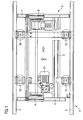
- FIG. 1 shows a plan view of a lifting device is shown, from which shows the position of the linear drives according to the invention.
- the reference numeral 1 designates the first conveyor track, which consists of the parallel conveyors 2 and 3, which are each equipped with roller chains 4.
- 5 with the second conveyor track is referred to, which also consists of two parallel conveyor sections 6 and 7, which are also equipped with roller chains 8.
- the second conveyor track 5 is with a framework, which is indicated at 9 assembled to a lifting device which is raised and lowered by means of the arranged in the corner regions of the lifting device 9 linear actuators 10 (perpendicular to the drawing plane).
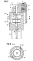
- the linear drive consists in the embodiment of Figure 2 from the ball screw 14, which consists of the ball screw 15 and the ball nut 16. Both are arranged in the gear housing 17, which is screwed to the frame part 18. At the lower part of the housing 17 designed as a pneumatic cylinder pressure medium cylinder 19 is attached, the piston rod 20 rests against the lower end face of the ball screw 15.
- the ball nut 16 is rotatable but non-displaceable in the direction of its axis of rotation, mounted in the housing 17, while the ball screw 15 is movable within the thread of the ball nut 16. However, the ball screw 15 is secured via the anti-rotation 21, a feather key, in the housing 17 against rotation, so that upon rotation of the ball nut 16 of the ball screw, a linear movement is imposed.
- This linear movement is directed depending on the direction of rotation of the ball nut 16 up or down.
- the second conveyor track 5 is raised via the cross member and the side member (not shown), which move when moving the Ball screw 15 is moved down by reversing the direction of rotation of the ball nut down.
- all ball screw 10 (Fig. 1) are synchronized with each other, which, as seen in Fig. 2, is achieved by means of an endless toothed belt 22, the teeth of the toothing of the toothed belt 22 corresponds, and the order the gear 23 is looped.
- This gear is fixedly connected to the ball nut 16 of the ball screw 14 and thus also rotates about the longitudinal axis of the ball screw 15.
- the all gears of all linear drives wraparound toothed belt 22 ensures that all gears 23 and thus all ball nuts 16 move at the same rotational speed and thus the ballscrews 15 mounted in the ball nuts 16 are moved up and down synchronously.
- a fluid-operated and an electric For driving the ball spindles, there are two options, namely a fluid-operated and an electric.
- a pneumatic cylinder 19 for the drive of the ball screw 15 is responsible.
- the piston rod 20 By extending the piston rod 20 when pressurizing the pneumatic cylinder 19 with compressed air, the ball screw is pushed upwards.
- the gear 23 which is connected to the ball nut this rotation must necessarily perform.
- all gears 23 are forced to rotate at the same rotational speed, with the result that all ball screws 15 of all linear drives synchronized up and down.
- the ball screw 15 is shown in the extended position, ie, the piston rod 20 of the pneumatic cylinder 19 is extended to its end position and presses against the end face 24 of the ball screw 15.
- the cross member 11 is in its upper position, ie in the transfer position of a workpiece or workpiece carrier from the second conveyor track on the first conveyor track.
- the second drive variant is shown, in which the toothed belt 22 is directly driven by the electric motor 10 via a spur gear 25, whereby the gears 23 are driven.
- the rotational movement of the gears causes the ball nuts 16 connected thereto to rotate, forcing the ball screws 15 to move linearly up and down within the ball nuts 16, depending on the direction in which the ball nuts 16 are driven via the gears 23.
- a synchronization of all four linear drives without additional synchronization aids takes place as a result of all the toothed wheels 23 looping around the belt drive.
- the synchronization prevents tilting or tilting of the workpieces or workpiece carriers on the second conveyor track, so that optionally the known in the prior art end coupling and angular mobility of the lifting rods can be omitted.
Landscapes
- Engineering & Computer Science (AREA)
- Mechanical Engineering (AREA)
- Transmission Devices (AREA)
- Intermediate Stations On Conveyors (AREA)
- Ship Loading And Unloading (AREA)
- Chain Conveyers (AREA)
Abstract
Description
Die Erfindung betrifft eine Vorrichtung zur Übergabe von Stückgut, insbesondere von Werkstückträgern, Werkstücken, Behältern oder Paletten, von einer ersten, aus zwei parallel und mit Abstand zueinander verlaufenden sowie das Stückgut tragenden Förderern bestehenden Förderbahn auf eine angrenzende zweite Förderbahn, mit einer Hubvorrichtung, die mittels mehrerer vertikaler, in den Eckbereichen der Hubvorrichtung angeordneter Linearantriebe zwischen einer unter der Förderebene der ersten Förderbahn gelegenen Ruhestellung und einer über dieser Förderebene gelegene Übergabestellung heb- und senkbar ist.The invention relates to a device for transferring piece goods, in particular of workpiece carriers, workpieces, containers or pallets, from a first, from two parallel and spaced running and the unit load carrying conveyors existing conveyor track on an adjacent second conveyor track, with a lifting device, the can be raised and lowered by means of a plurality of vertical, arranged in the corner regions of the lifting linear actuators between a lying below the conveying plane of the first conveyor line rest position and a location above this conveying level transfer position.
Aus der
Aus der
Die
Die vorliegende Erfindung hat sich deshalb die Aufgabe gestellt, die bekannte Vorrichtung zur Übergabe von Stückgut so zu verbessern, dass während des gesamten Hubvorganges eine stetige Synchronisation der Linearantriebe erfolgt, so dass ein Klemmen oder Verkanten der Hubvorrichtung sicher vermieden wird.The present invention has therefore set itself the task to improve the known device for the transfer of general cargo so that during the entire lifting a steady synchronization of the linear drives takes place, so that jamming or tilting of the lifting device is reliably avoided.
Zur Lösung der Aufgabe wird erfindungsgemäß vorgeschlagen, dass die Linearantriebe als Kugelgewindegetriebe mit Kugeln- , spindeln und Mutter ausgebildet sind und dass jede Kugelmutter mit einem achsparallelen Zahnrad gekoppelt ist und dass alle Zahnräder der Kugelmuttern zu deren Synchronisation mechanisch untereinander gekoppelt sind. Alle Linearantriebe sind im Gleichlauf antreibbar. Kugelgewindegetriebe sind Präzisionslinearantriebe, die nicht nur eine exakte Führung ermöglichen, sondern auch mit geringer Reibung hohe Kräfte, auch solche in Querrichtung, aufnehmen können. Durch Anordnung mehrerer Kugelgewindegetriebe und Antreiben der Linearantriebe im Gleichlauf kann bei einer gattungsgemäßen Vorrichtung sichergestellt werden, dass auch nicht zentrische hohe Kräfte sicher gehoben, gesenkt und übergeben werden können.To achieve the object, the invention proposes that the linear actuators are designed as ball screws with balls, spindles and nuts and that each ball nut is coupled with an axis-parallel gear and that all the gears of the ball nuts are mechanically coupled to each other to synchronize. All linear drives can be driven in synchronism. Ball screw drives are precision linear drives, which not only allow precise guidance, but can also absorb high forces, including those in the transverse direction, with low friction. By arranging a plurality of ball screws and driving the linear drives in synchronism can be ensured in a generic device that not centric high forces can be safely raised, lowered and handed over.
In einer Ausgestaltung der Erfindung ist es vorgesehen, dass die Kugelspindeln der Kugelgewindegetriebe jeweils linear beweglich, aber verdrehfest, in Kugelmuttern gelagert sind, die ihrerseits jeweils in Längsrichtung der Kugelspindeln fest, aber um die Längsachse der Kugelspindeln drehbar an der Hubeinheit gelagert sind. Durch Verdrehen der Kugelmuttern wird die Kugelspindel gezwungen, sich in ihrer Längsrichtung nach oben oder unten zu bewegen, je nachdem in welcher Drehrichtung die Mutter verdreht wird.In one embodiment of the invention, it is provided that the ball screws of the ball screw gear are each linearly movable, but rotationally fixed, mounted in ball nuts, which in turn are fixed respectively in the longitudinal direction of the ball spindles, but rotatably mounted on the lifting unit about the longitudinal axis of the ball spindles. By turning the ball nuts, the ball screw is forced to move in its longitudinal direction up or down, depending on the direction in which the nut is rotated.
In einer günstigen Ausgestaltung der Erfindung ist vorgesehen, dass jede Kugelmutter mit einem achsparallelen Zahnrad gekoppelt ist und das alle Zahnräder der Kugelmuttern zu deren Synchronisation mechanisch untereinander gekoppelt sind. Durch diesen Vorschlag der Erfindung wird sichergestellt, dass beim Verdrehen einer der Kugelmuttern alle anderen Kugelmuttern im Gleichlauf gedreht werden, weil die mit den Kugelmuttern gekoppelten Zahnräder ihrerseits miteinander gekoppelt sind. Das Verdrehen der Kugelmuttern im Gleichlauf bewirkt folglich gleichzeitig eine Linearverschiebung aller Kugelspindeln, ebenfalls im Gleichlauf, so dass in Folge der Synchronisation die Hubeinheit parallel zu sich selbst funktionssicher und einfach gehoben und gesenkt werden kann.In a favorable embodiment of the invention it is provided that each ball nut is coupled with an axis-parallel gear and all the gears of the ball nuts are mechanically coupled to each other to synchronize them. This proposal of the invention ensures that when turning one of the ball nuts all other ball nuts are rotated in synchronism, because the coupled with the ball nuts gears are in turn coupled together. The rotation of the ball nuts in synchronism consequently simultaneously causes a linear displacement of all ball spindles, also in synchronism, so that as a result of the synchronization, the lifting unit can be raised and lowered in parallel to itself functionally reliable and easy.
Wenn nach einem weiteren günstigen Merkmal der Erfindung vorgesehen ist, dass alle Zahnräder der Kugelmuttern in einer gemeinsamen horizontalen Ebene angeordnet sind und von einem endlosen Zahnriemen oder einer Kette umschlungen werden, so wird ein Kuppelmechanismus geschaffen, mit dem die Synchronisation aller Zahnräder und damit aller Kugelmuttern auf einfache Weise verwirklicht werden kann.If it is provided according to a further advantageous feature of the invention that all the gears of the ball nuts are arranged in a common horizontal plane and are wrapped by an endless toothed belt or a chain, a coupling mechanism is provided with which the synchronization of all gears and thus all the ball nuts can be realized in a simple manner.
In einer einfachen Ausführung ist jedes Zahnrad mit der jeweiligen Kugelmutter koaxial verbunden, d.h. das Zahnrad ist beispielsweise stirnseitig mit der Kugelmutter verschraubt. Die um die Zahnräder geschlungene Kette oder der Zahnriemen verteilt das Drehmoment von einer Kugelmutter auf die weiteren Kugelmuttern und stellt somit ein synchronisiertes Verdrehen aller Kugelmuttern sicher.In a simple embodiment, each gear is coaxially connected to the respective ball nut, i. the gear is, for example screwed frontally with the ball nut. The looped around the gears chain or timing belt distributes the torque of a ball nut on the other ball nuts and thus ensures a synchronized rotation of all ball nuts.
Die Kette oder der Zahnriemen können sowohl als einfaches Koppelglied wie auch als Antriebsglied verwendet werden. In einer einfachen Form sieht die Erfindung vor, die Linearbewegung der Kugelnspindeln durch Druckmittelzylinder zu erzeugen, die stirnseitig an die Kugelspindeln anlegbar sind. In einem solchen Fall bewirkt die jeweilige Kugelspindel bei ihrer Linearbewegung über die Gewindesteigung zwischen Kugelspindel und Kugelmutter ein Verdrehen des die Kugelspindel umgreifenden Zahnrades. Da das Zahnrad mit den Zahnrädern der anderen Kugelspindeln mechanisch gekoppelt ist, werden alle von den Druckmittelzylindern angetriebenen Kugelspindeln zwangsläufig synchronisiert.The chain or the toothed belt can be used both as a simple coupling member as well as a drive member. In a simple form, the invention provides for the linear movement of the ballscrews to be produced by pressure medium cylinders, which can be applied to the ball spindles on the face side. In such a case causes the respective ball screw in its linear movement on the thread pitch between the ball screw and ball nut, a rotation of the ball screw encompassing gear. Since the gear is mechanically coupled to the gears of the other ball spindles, all driven by the pressure medium cylinders ball spindles are inevitably synchronized.
Es ist aber auch, wie ein anderes Merkmal der Erfindung vorschlägt möglich, die Linearbewegung der Kugelspindeln über die Kugelmuttern einzuleiten, indem der die Zahnräder umschlingende Zahnriemen oder die Kette antreibbar ist. In diesem Fall wird, wie eine weitere Ausgestaltung der Erfindung vorschlägt, beispielsweise als Antrieb des Zahnriemens oder der Kette ein Elektromotor verwendet, wobei ein einziger Motor für alle Linearantriebe ausreicht. Das Antriebsmoment wird von dem Antriebsstirnrad des Elektromotors über den Zahnriemen oder die Kette auf die jeweiligen, mit der Kugelmutter gekoppelten Zahnräder übertragen, die ihrerseits, in Drehbewegung versetzt, eine Linearbewegung der Kugelspindeln verursachen.But it is also, as another feature of the invention suggests possible to initiate the linear movement of the ball spindles on the ball nuts by the toothed wheels belt or chain is driven drivable. In this case, as a further embodiment of the invention suggests, for example, used as a drive of the toothed belt or chain, an electric motor, wherein a single motor is sufficient for all linear drives. The drive torque is transmitted from the drive spur wheel of the electric motor via the toothed belt or the chain to the respective, coupled to the ball nut gears, which in turn, in rotation, causing a linear movement of the ball spindles.
Es ist schließlich auch denkbar, die Linearbewegung der Kugelspindeln durch die Kombination eines den Zahnriemen oder die Kette antreibenden Elektromotors mit die Kugelspindeln stirnseitig verschiebenden Druckmittelzylindern einzuleiten. Die Druckmittelzylinder können, wie beim Stand der Technik einfache und leichte Pneumatikzylinder sein, da das Problem der Synchronisation durch die erfindungsgemäße Verwendung der Kugelgewindegetriebe gelöst ist.Finally, it is also conceivable to initiate the linear movement of the ball spindles by the combination of an electric motor driving the toothed belt or the chain with the ball spindles which displace the pressure medium cylinders on the front side. The pressure medium cylinders can, as in the prior art, be simple and lightweight pneumatic cylinders, since the problem of synchronization is solved by the use according to the invention of the ball screw drives.
Ein Ausführungsbeispiel der Erfindung ist in der Zeichnung dargestellt und wird nachfolgend beschrieben. Es zeigen:
- Figur 1
- eine Draufsicht auf eine Hubvorrichtung nach der Erfindung mit elektromotorischen Antrieb,
Figur 2- einen Linearantrieb einer erfindungsgemäßen Hubvorrichtung in abgesenkter Stellung,
- Figur 3
- einen Schnitt durch das Kugelgewindegetriebe,
Figur 4- den Linearantrieb nach Figur 1 in angehobener Position und
Figur 5- die Vorrichtung mit elektromotorischem Antrieb.
- FIG. 1
- a top view of a lifting device according to the invention with electric motor drive,
- FIG. 2
- a linear drive of a lifting device according to the invention in a lowered position,
- FIG. 3
- a section through the ball screw gear,
- FIG. 4
- the linear drive of Figure 1 in the raised position and
- FIG. 5
- the device with electric motor drive.
In Figur 1 ist eine Draufsicht auf eine Hubvorrichtung dargestellt, aus der die Position der erfindungsgemäßen Linearantriebe hervorgeht. In Figur 1 ist insgesamt mit 1 die erste Förderbahn bezeichnet, die aus den parallel zueinander verlaufenden Förderern 2 und 3 besteht, die jeweils mit Rollenketten 4 bestückt sind. Mit 5 ist die zweite Förderbahn bezeichnet, die ebenfalls aus zwei parallelen Fördererabschnitten 6 und 7 besteht, die ebenfalls mit Rollenketten 8 bestückt sind. Die zweite Förderbahn 5 ist mit einem Rahmen, der bei 9 angedeutet ist zu einer Hubvorrichtung zusammengefügt, die mit Hilfe der in den Eckbereichen der Hubvorrichtung 9 angeordneten Linearantriebe 10 (senkrecht zur Zeichnungsebene) heb- und senkbar ist.1 shows a plan view of a lifting device is shown, from which shows the position of the linear drives according to the invention. In FIG. 1, the reference numeral 1 designates the first conveyor track, which consists of the
Die Ausbildung eines derartigen Linearantriebes ist deutlicher in der Zeichnungsfigur 2 zu erkennen, die einen Querschnitt durch einen der vier identisch ausgebildeten Linearantriebe zeigt. In der Zeichnung ist im oberen Bereich ein Querträger 11 zu erkennen, an dem die (hier nicht dargestellten) Längsträger befestigt sind, die die Förderer 6 und 7 der zweiten Förderbahn 5 mit den Rollenketten 8 tragen. Rechts in der Zeichnung ist im Querschnitt die Rollenkette 4 der ersten Förderbahn zu erkennen, die in einem Aluminium-Strangpressprofil 12 endlos umlaufend geführt ist, wobei das Strangpressprofil 12, wie bei 13 dargestellt, seitlich abgedeckt ist.The formation of such a linear drive can be seen more clearly in the drawing figure 2, which shows a cross section through one of the four identically designed linear drives. In the drawing, a
Der Linearantrieb besteht im Ausführungsbeispiel nach Figur 2 aus dem Kugelgewindegetriebe 14, das aus der Kugelspindel 15 und der Kugelmutter 16 besteht. Beide sind in dem Getriebegehäuse 17 angeordnet, das an dem Rahmenteil 18 angeschraubt ist. Am unteren Teil des Gehäuses 17 ist der als Pneumatikzylinder ausgeführte Druckmittelzylinder 19 angesetzt, dessen Kolbenstange 20 an der unteren Stirnseite der Kugelspindel 15 anliegt. Die Kugelmutter 16 ist drehbar, aber in Richtung ihrer Drehachse unverschiebbar, im Gehäuse 17 gelagert, während die Kugelspindel 15 innerhalb des Gewindes der Kugelmutter 16 bewegbar ist. Allerdings ist die Kugelspindel 15 über die Verdrehsicherung 21, einer Passfeder, im Gehäuse 17 gegen Verdrehung gesichert, so dass beim Verdrehen der Kugelmutter 16 der Kugelspindel eine Linearbewegung aufgezwungen wird. Diese Linearbewegung ist je nach Drehrichtung der Kugelmutter 16 nach oben oder unten gerichtet. Beim Aufwärtsbewegen der Kugelspindel 15 wird über den Querträger und den (nicht dargestellten) Längsträger die zweite Förderbahn 5 angehoben, die beim Bewegen der Kugelspindel 15 nach unten durch Drehrichtungsumkehr der Kugelmutter nach unten bewegt wird.The linear drive consists in the embodiment of Figure 2 from the
Es ist der wesentliche Kern der Erfindung, dass alle Kugelspindel 10 (Fig. 1) miteinander synchronisierbar sind, was, wie in Fig. 2 erkennbar, mittels eines endlosen Zahnriemens 22 erreicht wird, dessen Verzahnung der Verzahnung des Zahnriemens 22 entspricht, und der um das Zahnrad 23 geschlungen ist. Dieses Zahnrad ist mit der Kugelmutter 16 des Kugelgewindegetriebes 14 fest verbunden und dreht somit ebenfalls um die Längsachse der Kugelspindel 15. Der alle Zahnräder aller Linearantriebe umschlingende Zahnriemen 22 stellt sicher, dass sich alle Zahnräder 23 und damit alle Kugelmuttern 16 mit gleicher Drehgeschwindigkeit bewegen und somit die in den Kugelmuttern 16 gelagerten Kugelspindeln 15 synchron auf- und abbewegt werden.It is the essential core of the invention that all ball screw 10 (Fig. 1) are synchronized with each other, which, as seen in Fig. 2, is achieved by means of an endless
Zum Antreiben der Kugelspindeln gibt es zwei Möglichkeiten, nämlich eine druckmittelbetriebene und eine elektrische. Im Ausführungsbeispiel nach Figur 2 ist ein Pneumatikzylinder 19 für den Antrieb der Kugelspindel 15 verantwortlich. Durch Ausfahren der Kolbenstange 20 beim Beaufschlagen des Pneumatikzylinders 19 mit Druckluft wird die Kugelspindel nach oben gedrückt. In Folge der reibungsarmen Lagerung im Kugelgewindegetriebes 14 wird durch die Linearbewegung der gegen Verdrehung gesicherten Kugelspindel 15, zwangsweise die Kugelmutter 16 in Drehung versetzt, so dass das Zahnrad 23, das mit der Kugelmutter verbunden ist, diese Drehbewegung zwangsläufig mit ausführen muss. Da das Zahnrad aber mit den benachbarten Zahnrädern der übrigen Kugelmuttern über den Zahnriemen 22 verbunden ist, sind alle Zahnräder 23 gezwungen, mit gleicher Drehgeschwindigkeit umzulaufen, mit dem Ergebnis, dass alle Kugelspindeln 15 aller Linearantriebe synchronisiert auf- und abbewegt werden.For driving the ball spindles, there are two options, namely a fluid-operated and an electric. In the embodiment of Figure 2 is a
In Figur 4 ist die Kugelspindel 15 in ausgefahrener Stellung dargestellt, d.h. die Kolbenstange 20 des Pneumatikzylinders 19 ist in ihre Endstellung ausgefahren und drückt gegen die Stirnseite 24 der Kugelspindel 15. In dieser Stellung steht der Querträger 11 in seiner oberen Stellung, d.h. in der Übergabestellung eines Werkstückes oder Werkstückträgers von der zweiten Förderbahn auf die erste Förderbahn.In Figure 4, the
In Figur 5 ist die zweite Antriebsvariante dargestellt, bei der der Zahnriemen 22 durch den Elektromotor 10 über ein Stirnrad 25 unmittelbar angetrieben wird, wodurch die Zahnräder 23 angetrieben werden. Durch die Drehbewegung der Zahnräder werden die mit diesen verbundenen Kugelmuttern 16 in Drehung versetzt, die die Kugelspindeln 15 zwingt, sich innerhalb der Kugelmuttern 16 linear auf und ab zu bewegen, je nachdem in welcher Richtung die Kugelmuttern 16 über die Zahnräder 23 angetrieben werden. Auch hier erfolgt in Folge des alle Zahnräder 23 umschlingenden Zahnriemenantriebes eine Synchronisation aller vier Linearantriebe ohne zusätzliche Synchronisationshilfsmittel. Die Synchronisation verhindert ein Kippen oder Schrägstellen der Werkstücke oder Werkstückträger auf der zweiten Förderbahn, so dass gegebenenfalls die im Stand der Technik bekannte Endkopplung und Winkelbeweglichkeit der Hubstangen entfallen kann.In Figure 5, the second drive variant is shown, in which the
Es ist auch möglich, den Antrieb über den Elektromotor 24 mit dem Antrieb über den Pneumatikzylinder 19 zu kombinieren; auch hier werden die Vorteile der vorliegenden Erfindung erreicht, die insbesondere in den synchronen und einfachen Bewegungsabläufen der Linearantriebe zu sehen sind, wodurch auch große Werkstückgewichte gehoben und gesenkt werden können.It is also possible to combine the drive via the
Claims (8)
- Device for transferring piece goods, in particular workpiece holders, workpieces, containers or pallets, from a first conveyor track (1) consisting of two conveyors (2, 3) running parallel to and at a distance from each other and conveying the piece goods to an adjacent second conveyor track, said transfer device comprising a lifting device (9) which can be raised and lowered by means of a plurality of vertical linear drives (14) arranged in the corner areas of the lifting device between an idle position located under the conveying plane of the first conveyor track (1) and a transfer position located above said conveying plane, characterised in that the linear drives are embodied as ball-and-screw spindle gears (14) having ball spindle (15) and ball nut (16) and that each ball nut (16) is coupled to an axially parallel gear wheel (23) and that all the gear wheels (23) of the ball nuts (16) are mechanically coupled to one another for the purpose of their synchronisation.
- Device for transferring piece goods according to claim 1, characterised in that the ball spindles (15) of the ball-and-screw spindle gear (14) are in each case mounted in the ball nuts (16) in a linearly movable but torsionally rigid manner, which ball nuts (16) for their part are in each case mounted on the lifting device firmly in the longitudinal direction of the ball spindle (15), yet can rotate about the longitudinal axis of the ball spindles (15).
- Device according to claim 1 or 2, characterised in that all the gear wheels (23) of the ball nuts (16) are arranged in a common horizontal plane and are encircled by an endless toothed belt (22) or a chain.
- Device according to one of the preceding claims, characterised in that each gear wheel (23) is coaxially connected to the respective ball nut (16) and encompasses the ball spindle (15).
- Device according to one of the preceding claims, characterised in that the linear movement of the ball spindles (15) can be generated by means of pressurising medium cylinders (19) which can be applied to the front face of the ball spindles.
- Device according to one of the preceding claims, characterised in that the linear movement of the ball spindles (15) can be initiated via the ball nuts in that the toothed belt (22) or chain wound around the gear wheels can be driven.
- Device according to one of the preceding claims, characterised in that an electric motor (24) is provided as the drive of the toothed belt (22) or chain.
- Device according to one of the preceding claims, characterised in that the linear movement of the ball spindles (15) can be initiated by the combination of an electric motor (24) driving the toothed belt (22) or chain with a pneumatic cylinder drive (19) displacing the ball spindles (15) on the front face.
Applications Claiming Priority (2)
| Application Number | Priority Date | Filing Date | Title |
|---|---|---|---|
| DE10341109A DE10341109A1 (en) | 2003-09-05 | 2003-09-05 | Device for transferring general cargo |
| DE10341109 | 2003-09-05 |
Publications (3)
| Publication Number | Publication Date |
|---|---|
| EP1512648A2 EP1512648A2 (en) | 2005-03-09 |
| EP1512648A3 EP1512648A3 (en) | 2006-03-01 |
| EP1512648B1 true EP1512648B1 (en) | 2007-09-12 |
Family
ID=34129668
Family Applications (1)
| Application Number | Title | Priority Date | Filing Date |
|---|---|---|---|
| EP04017780A Expired - Fee Related EP1512648B1 (en) | 2003-09-05 | 2004-07-27 | Articles transferring device |
Country Status (4)
| Country | Link |
|---|---|
| EP (1) | EP1512648B1 (en) |
| AT (1) | ATE372944T1 (en) |
| DE (2) | DE10341109A1 (en) |
| ES (1) | ES2290595T3 (en) |
Families Citing this family (4)
| Publication number | Priority date | Publication date | Assignee | Title |
|---|---|---|---|---|
| CN104108597A (en) * | 2014-06-27 | 2014-10-22 | 长兴华锐机械设备有限公司 | Automatic load-shifting lifting platform lifting mechanism |
| CN108408357A (en) * | 2018-05-09 | 2018-08-17 | 新昌县大雄锻造有限公司 | A kind of round steel processing feeding device |
| CN111289285A (en) * | 2020-02-12 | 2020-06-16 | 镇江北新建材有限公司 | Full-automatic synchronous sampling system of gypsum board |
| CN111392321B (en) * | 2020-04-22 | 2021-12-28 | 重庆市南川区友邦经贸运输有限责任公司 | Automatic transportation platform of commodity circulation |
Family Cites Families (6)
| Publication number | Priority date | Publication date | Assignee | Title |
|---|---|---|---|---|
| DE3012355A1 (en) * | 1980-03-29 | 1981-10-08 | Robert Bosch Gmbh, 7000 Stuttgart | DEVICE FOR IMPLEMENTING TRANSPORT BELTS |
| DE4236362A1 (en) * | 1992-10-28 | 1994-05-05 | Kolbus Gmbh & Co Kg | Discharge mechanism for bookbinding sticking machine - has deposition device, following transverse stacking conveyor taking over book block(s) |
| WO1997004928A1 (en) * | 1995-07-27 | 1997-02-13 | Ken Yanagisawa | Moving mechanism |
| DE4439106C1 (en) * | 1994-11-02 | 1996-05-30 | Bosch Gmbh Robert | Conveyor track for transfer of tooling pieces |
| DE19603554A1 (en) * | 1996-02-01 | 1997-08-07 | Bosch Gmbh Robert | Relocation of workpieces or workpiece carriers |
| DE19818604C2 (en) * | 1998-04-20 | 2000-05-18 | Mannesmann Ag | Device for transferring piece goods, in particular workpiece carriers, workpieces, containers or pallets |
-
2003
- 2003-09-05 DE DE10341109A patent/DE10341109A1/en not_active Withdrawn
-
2004
- 2004-07-27 ES ES04017780T patent/ES2290595T3/en active Active
- 2004-07-27 AT AT04017780T patent/ATE372944T1/en active
- 2004-07-27 DE DE502004004928T patent/DE502004004928D1/en active Active
- 2004-07-27 EP EP04017780A patent/EP1512648B1/en not_active Expired - Fee Related
Also Published As
| Publication number | Publication date |
|---|---|
| ATE372944T1 (en) | 2007-09-15 |
| DE10341109A1 (en) | 2005-04-14 |
| ES2290595T3 (en) | 2008-02-16 |
| DE502004004928D1 (en) | 2007-10-25 |
| EP1512648A3 (en) | 2006-03-01 |
| EP1512648A2 (en) | 2005-03-09 |
Similar Documents
| Publication | Publication Date | Title |
|---|---|---|
| DE2359912C2 (en) | Transfer device for a transfer press | |
| EP0672480B1 (en) | Transportsystem | |
| EP0850709B1 (en) | Transfer device and multistage press | |
| EP1423231B1 (en) | Screwing station | |
| DE3629069A1 (en) | PALLET FEEDING DEVICE FOR AT LEAST ONE MACHINE TOOL | |
| EP0930110B1 (en) | Conveying device | |
| EP0671228A2 (en) | Transporting equipment for work pieces in a press | |
| DE3235646C2 (en) | ||
| DE10122377C1 (en) | Return apparatus for transferring machined workpieces between machining units, comprises transfer table and lifting table with workpiece supports | |
| DE2119479B2 (en) | Support frame for freight containers of different lengths | |
| DE2806987C3 (en) | Device for manipulating workpieces | |
| EP1512648B1 (en) | Articles transferring device | |
| DE10106193B4 (en) | lifting unit | |
| CH650473A5 (en) | DEFLECTION DEVICE FOR TRANSPORT RAILWAYS. | |
| EP0857152B1 (en) | Method and device for extracting rolling pallets in compact storage technology, and rolling pallet therefor | |
| DE2430737C3 (en) | Turntable | |
| DD214083A1 (en) | DEVICE FOR TRANSPORTING EXAMPLE PALLETS THROUGH CHAIN DRIVE | |
| EP0650781B1 (en) | Driving device for a multi-axle transport of work pieces in a transfer press | |
| DE3703920C2 (en) | ||
| DE4320431B4 (en) | Transfer Press complex | |
| EP1073581B1 (en) | Transporting device, especially a transport beam transporting device | |
| DE19833113A1 (en) | Bearing for a cylinder in a printing press | |
| DE3422524A1 (en) | Tensioning and positioning device for a transfer machine | |
| EP1256416B1 (en) | Crank drive for the recirculation of machined parts | |
| DE10348643B3 (en) | Workpiece transport device for press using carrier beams extending in transport direction each supported at either end via lever mechanism coupled to linear drive unit |
Legal Events
| Date | Code | Title | Description |
|---|---|---|---|
| PUAI | Public reference made under article 153(3) epc to a published international application that has entered the european phase |
Free format text: ORIGINAL CODE: 0009012 |
|
| AK | Designated contracting states |
Kind code of ref document: A2 Designated state(s): AT BE BG CH CY CZ DE DK EE ES FI FR GB GR HU IE IT LI LU MC NL PL PT RO SE SI SK TR |
|
| AX | Request for extension of the european patent |
Extension state: AL HR LT LV MK |
|
| PUAL | Search report despatched |
Free format text: ORIGINAL CODE: 0009013 |
|
| AK | Designated contracting states |
Kind code of ref document: A3 Designated state(s): AT BE BG CH CY CZ DE DK EE ES FI FR GB GR HU IE IT LI LU MC NL PL PT RO SE SI SK TR |
|
| AX | Request for extension of the european patent |
Extension state: AL HR LT LV MK |
|
| 17P | Request for examination filed |
Effective date: 20060821 |
|
| AKX | Designation fees paid |
Designated state(s): AT DE ES FR GB IT |
|
| 17Q | First examination report despatched |
Effective date: 20061026 |
|
| GRAP | Despatch of communication of intention to grant a patent |
Free format text: ORIGINAL CODE: EPIDOSNIGR1 |
|
| GRAS | Grant fee paid |
Free format text: ORIGINAL CODE: EPIDOSNIGR3 |
|
| GRAA | (expected) grant |
Free format text: ORIGINAL CODE: 0009210 |
|
| AK | Designated contracting states |
Kind code of ref document: B1 Designated state(s): AT DE ES FR GB IT |
|
| REG | Reference to a national code |
Ref country code: GB Ref legal event code: FG4D Free format text: NOT ENGLISH |
|
| GBT | Gb: translation of ep patent filed (gb section 77(6)(a)/1977) |
Effective date: 20070912 |
|
| REF | Corresponds to: |
Ref document number: 502004004928 Country of ref document: DE Date of ref document: 20071025 Kind code of ref document: P |
|
| ET | Fr: translation filed | ||
| REG | Reference to a national code |
Ref country code: ES Ref legal event code: FG2A Ref document number: 2290595 Country of ref document: ES Kind code of ref document: T3 |
|
| PLBE | No opposition filed within time limit |
Free format text: ORIGINAL CODE: 0009261 |
|
| STAA | Information on the status of an ep patent application or granted ep patent |
Free format text: STATUS: NO OPPOSITION FILED WITHIN TIME LIMIT |
|
| 26N | No opposition filed |
Effective date: 20080613 |
|
| PGFP | Annual fee paid to national office [announced via postgrant information from national office to epo] |
Ref country code: ES Payment date: 20130807 Year of fee payment: 10 Ref country code: DE Payment date: 20130918 Year of fee payment: 10 Ref country code: AT Payment date: 20130607 Year of fee payment: 10 |
|
| PGFP | Annual fee paid to national office [announced via postgrant information from national office to epo] |
Ref country code: GB Payment date: 20130710 Year of fee payment: 10 Ref country code: FR Payment date: 20130724 Year of fee payment: 10 |
|
| PGFP | Annual fee paid to national office [announced via postgrant information from national office to epo] |
Ref country code: IT Payment date: 20130726 Year of fee payment: 10 |
|
| REG | Reference to a national code |
Ref country code: DE Ref legal event code: R119 Ref document number: 502004004928 Country of ref document: DE |
|
| REG | Reference to a national code |
Ref country code: AT Ref legal event code: MM01 Ref document number: 372944 Country of ref document: AT Kind code of ref document: T Effective date: 20140727 |
|
| GBPC | Gb: european patent ceased through non-payment of renewal fee |
Effective date: 20140727 |
|
| REG | Reference to a national code |
Ref country code: FR Ref legal event code: ST Effective date: 20150331 |
|
| PG25 | Lapsed in a contracting state [announced via postgrant information from national office to epo] |
Ref country code: IT Free format text: LAPSE BECAUSE OF NON-PAYMENT OF DUE FEES Effective date: 20140727 Ref country code: DE Free format text: LAPSE BECAUSE OF NON-PAYMENT OF DUE FEES Effective date: 20150203 |
|
| REG | Reference to a national code |
Ref country code: DE Ref legal event code: R119 Ref document number: 502004004928 Country of ref document: DE Effective date: 20150203 |
|
| PG25 | Lapsed in a contracting state [announced via postgrant information from national office to epo] |
Ref country code: AT Free format text: LAPSE BECAUSE OF NON-PAYMENT OF DUE FEES Effective date: 20140727 Ref country code: FR Free format text: LAPSE BECAUSE OF NON-PAYMENT OF DUE FEES Effective date: 20140731 Ref country code: GB Free format text: LAPSE BECAUSE OF NON-PAYMENT OF DUE FEES Effective date: 20140727 |
|
| REG | Reference to a national code |
Ref country code: ES Ref legal event code: FD2A Effective date: 20160202 |
|
| PG25 | Lapsed in a contracting state [announced via postgrant information from national office to epo] |
Ref country code: ES Free format text: LAPSE BECAUSE OF NON-PAYMENT OF DUE FEES Effective date: 20140728 |