EP1512573A2 - Bouchon de réservoir de carburant - Google Patents
Bouchon de réservoir de carburant Download PDFInfo
- Publication number
- EP1512573A2 EP1512573A2 EP04020927A EP04020927A EP1512573A2 EP 1512573 A2 EP1512573 A2 EP 1512573A2 EP 04020927 A EP04020927 A EP 04020927A EP 04020927 A EP04020927 A EP 04020927A EP 1512573 A2 EP1512573 A2 EP 1512573A2
- Authority
- EP
- European Patent Office
- Prior art keywords
- valve
- pressure valve
- flow path
- negative pressure
- positive pressure
- Prior art date
- Legal status (The legal status is an assumption and is not a legal conclusion. Google has not performed a legal analysis and makes no representation as to the accuracy of the status listed.)
- Granted
Links
Images




Classifications
-
- B—PERFORMING OPERATIONS; TRANSPORTING
- B60—VEHICLES IN GENERAL
- B60K—ARRANGEMENT OR MOUNTING OF PROPULSION UNITS OR OF TRANSMISSIONS IN VEHICLES; ARRANGEMENT OR MOUNTING OF PLURAL DIVERSE PRIME-MOVERS IN VEHICLES; AUXILIARY DRIVES FOR VEHICLES; INSTRUMENTATION OR DASHBOARDS FOR VEHICLES; ARRANGEMENTS IN CONNECTION WITH COOLING, AIR INTAKE, GAS EXHAUST OR FUEL SUPPLY OF PROPULSION UNITS IN VEHICLES
- B60K15/00—Arrangement in connection with fuel supply of combustion engines or other fuel consuming energy converters, e.g. fuel cells; Mounting or construction of fuel tanks
- B60K15/03—Fuel tanks
- B60K15/04—Tank inlets
- B60K15/0406—Filler caps for fuel tanks
-
- B—PERFORMING OPERATIONS; TRANSPORTING
- B60—VEHICLES IN GENERAL
- B60K—ARRANGEMENT OR MOUNTING OF PROPULSION UNITS OR OF TRANSMISSIONS IN VEHICLES; ARRANGEMENT OR MOUNTING OF PLURAL DIVERSE PRIME-MOVERS IN VEHICLES; AUXILIARY DRIVES FOR VEHICLES; INSTRUMENTATION OR DASHBOARDS FOR VEHICLES; ARRANGEMENTS IN CONNECTION WITH COOLING, AIR INTAKE, GAS EXHAUST OR FUEL SUPPLY OF PROPULSION UNITS IN VEHICLES
- B60K15/00—Arrangement in connection with fuel supply of combustion engines or other fuel consuming energy converters, e.g. fuel cells; Mounting or construction of fuel tanks
- B60K15/03—Fuel tanks
- B60K15/035—Fuel tanks characterised by venting means
- B60K15/03519—Valve arrangements in the vent line
-
- B—PERFORMING OPERATIONS; TRANSPORTING
- B60—VEHICLES IN GENERAL
- B60K—ARRANGEMENT OR MOUNTING OF PROPULSION UNITS OR OF TRANSMISSIONS IN VEHICLES; ARRANGEMENT OR MOUNTING OF PLURAL DIVERSE PRIME-MOVERS IN VEHICLES; AUXILIARY DRIVES FOR VEHICLES; INSTRUMENTATION OR DASHBOARDS FOR VEHICLES; ARRANGEMENTS IN CONNECTION WITH COOLING, AIR INTAKE, GAS EXHAUST OR FUEL SUPPLY OF PROPULSION UNITS IN VEHICLES
- B60K15/00—Arrangement in connection with fuel supply of combustion engines or other fuel consuming energy converters, e.g. fuel cells; Mounting or construction of fuel tanks
- B60K15/03—Fuel tanks
- B60K15/035—Fuel tanks characterised by venting means
- B60K2015/03542—Mounting of the venting means
- B60K2015/03547—Mounting of the venting means the venting means are integrated in the fuel cap or inlet cover
-
- Y—GENERAL TAGGING OF NEW TECHNOLOGICAL DEVELOPMENTS; GENERAL TAGGING OF CROSS-SECTIONAL TECHNOLOGIES SPANNING OVER SEVERAL SECTIONS OF THE IPC; TECHNICAL SUBJECTS COVERED BY FORMER USPC CROSS-REFERENCE ART COLLECTIONS [XRACs] AND DIGESTS
- Y10—TECHNICAL SUBJECTS COVERED BY FORMER USPC
- Y10S—TECHNICAL SUBJECTS COVERED BY FORMER USPC CROSS-REFERENCE ART COLLECTIONS [XRACs] AND DIGESTS
- Y10S220/00—Receptacles
- Y10S220/33—Gasoline tank cap
Definitions
- the present invention relates to a fuel cap having a pressure regulating valve that regulates the inner pressure of a fuel tank, and more specifically pertains to a mechanism of improving the flow characteristics of the pressure regulating valve.
- a known fuel cap includes a cap main body that is screwed to a fuel inlet of a fuel tank, and a pressure regulating valve that is attached to the cap main body to regulate the inner pressure of the fuel tank (see, for example, JP No. 10-278958A).
- the pressure regulating valve has a positive pressure valve and a negative pressure valve to regulate the inner pressure of the fuel tank within a preset range.
- the positive valve opens in response to an increase in inner pressure of the fuel tank to be higher than a predetermined level, while the negative valve opens in response to a decrease in inner pressure of the fuel tank to be lower than another predetermined level.
- the negative pressure valve has a restriction member on a negative pressure valve plug to increase the differential pressure applied to the valve plug and thereby abruptly heighten the flow rate in the open position of the negative pressure valve.
- the restriction member undesirably lowers the flow rate in the open position of the positive pressure valve and deteriorates the quick pressure regulation performance of the positive pressure valve.
- An object of the invention is to provide a fuel cap having the improved quick pressure regulation performance of a positive pressure valve.
- Another object of the invention is to provide a fuel cap that reduces passage resistance of a pressure regulating valve to enhance response, while decreasing the total number of required parts to attain cost reduction.
- the present invention is directed to a fuel cap, which includes a cap main body attached to a tank opening of a fuel tank and a pressure regulating valve that is received in the cap main body and opens and closes an intra-cap flow path formed in the cap main body to regulate an inner pressure of the fuel tank.
- the pressure regulating valve has a positive pressure valve that opens in response to an increase in inner pressure of the fuel tank to be higher than a first pressure level, and a negative pressure valve that opens in response to a decrease in inner pressure of the fuel tank to be lower than a second pressure level.
- the positive pressure valve has a positive pressure valve plug that opens and closes a first valve flow path, which forms part of the intra-cap flow path, and a first spring that has one end fixed to the cap main body and applies a pressing force in a closing direction to the positive pressure valve plug.
- the positive pressure valve plug includes: a positive pressure valve main body; a seat element that is formed on the positive pressure valve main body to face the first valve flow path and is seated on a first seating element provided on the cap main body to close the first valve flow path; a second valve flow path that is formed to pass through the positive pressure valve main body and forms part of the intra-cap flow path; and a second seating element that is formed on the positive pressure valve main body in a neighborhood of the second valve flow path.
- the negative pressure valve has a negative pressure valve plug that opens and closes the second valve flow path, and a second spring that has one end fixed to the cap main body and applies a pressing force in a closing direction to the negative pressure valve plug.
- the negative pressure valve plug includes: a cup-shaped negative pressure valve main body that has an upper wall and a cylindrical side wall that is protruded from outer circumference of the upper wall; a seat element that is formed on the upper wall and is seated on the second seating element to close the second valve flow path; and a restriction member that is located to face the first valve flow path and narrows an passage area of the first valve flow path in a closed position of the negative pressure valve plug, while widening the passage area of the first valve flow path in an open position of the positive pressure valve plug where the negative pressure valve plug moves integrally with the positive pressure valve plug.
- the pressure regulating valve opens and closes the intra-cap flow path to regulate the inner pressure of the fuel tank within a preset range.
- the positive pressure valve plug opens against the pressing force of the first spring in response to an increase in inner pressure of the fuel tank to be higher than the first pressure level.
- the negative pressure valve the negative pressure valve plug opens in response to a decrease in inner pressure of the fuel tank to be lower than the second pressure level. This arrangement effectively keeps the inner pressure of the fuel tank within the preset range.
- the restriction member provided on the negative pressure valve plug increases the differential pressure applied to the negative pressure valve plug in the negative pressure condition to improve the valve-opening characteristics.
- the restriction member widens the passage area of the first valve flow path in the positive pressure condition to abruptly increases the flow rate. This arrangement ensures the good flow characteristics of the positive pressure valve.
- the preferable present embodiment of the present invention is directed to a fuel cap that opens and closes a tank opening.
- the fuel cap includes: a closer that opens and closes the tank opening in a sealed state; a valve chest forming-member that is set on the closer to form a valve chest, which connects a tank with atmosphere; and a pressure regulating valve that is received in the valve chest and opens and closes a valve flow path formed in the valve chest, so as to regulate inner pressure of the tank.
- the pressure regulating valve has a valve plug that opens and closes the valve flow path and a spring that presses the valve plug in a closing direction.
- the spring has one end held to press the valve plug and the other end held by spring lock ends, which are formed by thermally caulking upper opening ends of the valve chest forming-member.
- the fuel cap of the invention has the pressure regulating valve placed in the valve chest formed in the shut-of member.
- the pressure regulating valve has the valve chest, which is pressed by the spring.
- the pressure regulating valve opens to regulate the inner pressure of the tank.
- the spring has one end held by the valve plug to press the valve plug and the other end held by the spring lock ends of the valve chest-forming member.
- the spring lock ends are formed by thermally caulking the opening ends of the valve chest-forming member. The opening of the valve chest is thus not closed over a wide area. This arrangement thus desirably reduces the passage resistance of the fluid flowing through the valve chest.
- the spring lock ends are formed by thermally caulking the opening ends of the valve chest-forming member. This arrangement does not require the inner cover, which is essentially included in the prior art structure, thus decreasing the total number of required parts and attaining cost reduction.
- Another embodiment of the invention is also directed to a manufacturing method of a fuel cap.
- the manufacturing method includes the steps of: placing a valve plug in a valve chest and setting a spring to have one end press the valve plug; temporarily holding the other end of the spring with a temporary joint jig to compress the spring; thermally caulking opening ends of a valve chest-forming member to form spring lock ends; and detaching the temporary joint jig from the other end of the spring and making the other end of the spring held by the spring lock ends.
- the pressure regulating valve is set in the fuel cap according to this manufacturing method of the invention.
- the other end of the spring is temporarily held by the temporary joint jig, before being held by the spring lock ends.
- the opening ends of the valve chest-forming member are thermally caulked to form the spring lock ends.
- No pressing force of the spring is applied to the opening ends of the valve chest-forming member, while the opening ends of the valve chest-forming member are thermally caulked to form the spring lock ends. This arrangement ensures easy formation of the spring lock ends.
- Fig. 1 is a sectional view illustrating the structure of a fuel cap in a first embodiment of the invention
- Fig. 2 is an enlarged sectional view showing the structure of a pressure regulating valve included in the fuel cap of Fig. 1;
- Fig. 3 is a decomposed sectional view of the pressure regulating valve
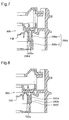
- Fig. 4 shows a valve-opening action in a positive pressure condition of the pressure regulating valve
- Fig. 5 shows a valve-opening action in a negative pressure condition of the pressure regulating valve
- Fig. 6 is a graph showing flow characteristics of the pressure regulating valve
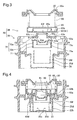
- Fig. 7 is a sectional view illustrating the structure of a pressure regulating valve in a second embodiment of the invention.
- Fig. 8 is a sectional view illustrating the structure of a pressure regulating valve in a third embodiment of the invention.
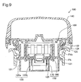
- Fig.9 is a sectional view illustrating the structure of a fuel cap in a fourth embodiment of the invention.
- Fig. 10 is a sectional view showing the structure of a pressure regulating valve included in the fuel cap of Fig. 9;
- Fig. 11 shows one step in an assembly process of the pressure regulating valve
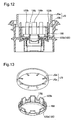
- Fig. 12 shows a step subsequent to Fig. 11 in the assembly process of the pressure regulating valve
- Fig. 13 is a perspective view showing the upper portion of a valve chest-forming member and a temporary joint jig;
- Fig. 14 shows a step subsequent to Fig. 12 in the assembly process of the pressure regulating valve
- Fig. 15 shows a valve-opening action of a positive pressure valve in the pressure regulating valve
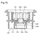
- Fig. 16 shows a valve-opening action of a negative pressure valve in the pressure regulating valve.
- Fig. 1 is a sectional view illustrating the structure of a fuel cap 10 in a first embodiment of the invention. As shown in Fig. 1, the fuel cap 10 is attached to a filler neck FN having a fuel inlet FNb (tank opening) to feed a supply of fuel to a fuel tank (not shown).
- a fuel inlet FNb tank opening
- the fuel cap 10 has a cap main body 20 that is made of a synthetic resin material like polyacetal, a cover 40 that has a handle and is made of a synthetic resin material like nylon and is mounted on the cap main body 20, an inner cover 30 that closes an upper opening of the cap main body 20 and forms a valve chest 25, a pressure regulating valve 50 that is received in the valve chest 25, a torque mechanism 80, and a gasket GS that is attached to the upper outer circumference of the cap main body 20 to seal the cap main body 20 from the filler neck FN.
- a cap main body 20 that is made of a synthetic resin material like polyacetal
- a cover 40 that has a handle and is made of a synthetic resin material like nylon and is mounted on the cap main body 20
- an inner cover 30 that closes an upper opening of the cap main body 20 and forms a valve chest 25, a pressure regulating valve 50 that is received in the valve chest 25, a torque mechanism 80, and a gasket GS that is attached to the upper outer circumference of the cap main body
- the cap main body 20 has a substantially cylindrical outer tubular member 20a with a cap engagement element 21, which engages with a mating element formed on the inner wall of the filler neck FN, and a valve chest-forming member 20b that is located in the lower portion of the inside of the outer tubular member 20a to form the valve chest 25.
- the valve chest-forming member 20b, the upper portion of the outer tubular member 20a, and the inner cover 30 set on the cap main body 20 define the valve chest 25.
- the pressure regulating valve 50 located in the valve chest 25 includes a positive pressure valve 60 and a negative pressure valve 70 to regulate the pressure in the fuel tank within a preset range.
- the gasket GS is set on a lower face of an upper flange 22 of the cap main body 20.
- the gasket GS is located between a seal support element 24 of the flange 22 and the fuel inlet FNb of the filler neck FN.
- the torque mechanism 80 gives a click when the rotational torque exceeds a specified level in the operator's closing action of the fuel cap 10. The operator thus confirms that the fuel cap 10 is tightly fastened with the rotational torque of not less than the specified level.
- Fig. 2 is an enlarged sectional view showing the structure of the pressure regulating valve 50.
- the pressure regulating valve 50 includes the positive pressure valve 60 and the negative pressure valve 70.
- the positive pressure valve 60 is located in an upper chamber 25a of the valve chest 25, while the negative pressure valve 70 is located in a lower chamber 25b of the valve chest 25.
- a first seating element 20f is formed on an outward inclined upper portion of the valve chest-forming member 20b between the upper chamber 25a and the lower chamber 25b.
- a first valve flow path 25d inside the first seating element 20f communicates with a connection hole 25c formed in a bottom 20d.
- the connection hole 25c is linked to the fuel tank via a non-illustrated filler pipe.
- the positive pressure valve 60 has a positive pressure valve plug 61 to open and close the first valve flow path 25d, a valve support member 65, and a first spring 68 that has one end fixed to the inner cover 30 and applies a pressing force in a closing direction to the positive pressure valve plug 61 via the valve support member 65.
- Fig. 3 is a decomposed sectional view of the pressure regulating valve 50.
- the positive pressure valve plug 61 has a disc-shaped positive pressure valve main body 62, which is made of, for example, fluororubber and has a through-hole and projections to exert the valve functions.
- the positive pressure valve main body 62 has a seat element 63a, which is seated on the first seating element 20f to close the first valve flow path 25d.
- the presence of a ring-shaped recess 63b formed on the upper outer circumference of the positive pressure valve main body 62 makes the thin-wall seat element 63a.
- the thin-wall seat element 63a is seated on the first seating element 20f and is elastically bent to enhance the sealing properties.
- a second valve flow path 63c is formed to pass through the center of the positive pressure valve main body 62 to connect with the first valve flow path 25d.
- a lower face of the positive pressure valve main body 62 forms a second seating element 63d in the vicinity of the second valve flow path 63c.
- the second seating element 63d works as a seating plane of the negative pressure valve 70 as discussed later.
- a ring-shaped groove 63e is formed on the lower face of the positive pressure valve main body 62 to be located inside the ring-shaped recess 63b. The ring-shaped groove 63e facilitates the elastic bending in the closed position of the positive pressure valve plug 61.
- a tubular fitting element 63f is formed upright on the center of the positive pressure valve plug 61 to encircle the second valve flow path 63c.
- a side support recess 63g is formed on the side of the tubular fitting element 63f.
- the tubular fitting element 63f is fit in a fitting hole 65a of the valve support member 65, so that the positive pressure valve plug 61 is set in the valve support member 65.
- An upper face of the valve support member 65 forms a spring support element 65b to support one end of the first spring 68.
- the other end of the first spring 68 is held by a support element 30a of the inner cover 30.
- the first spring 68 is accordingly spanned between the spring support element 65b and the inner cover 30.
- the negative pressure valve 70 includes a resin negative pressure valve plug 71 and a second spring 78 that is spanned between the negative pressure valve plug 71 and the bottom 20d to press the negative pressure valve plug 71.
- the negative pressure valve plug 71 has a cup-shaped negative pressure valve main body 72, which includes an upper wall 72a and a cylindrical side wall 72b protruded from the outer circumference of the upper wall 72a.
- the negative pressure valve main body 72 has projections to exert the valve functions.
- a circular ridge-like seat element 73a is formed on the upper wall 72a of the negative pressure valve main body 72 to be seated on the second seating element 63d of the positive pressure valve plug 61 and close the second valve flow path 63c.
- a ring-shaped projection 73c is protruded outward from the upper circumferential end of the side wall 72b to face the first valve flow path 25d.
- the ring-shaped projection 73c functions as a restriction member, which narrows the passage area of the first valve flow path 25d in the closed position of the negative pressure valve plug 71, while widening the passage area of the first valve flow path 24d in the open position of the positive pressure valve plug 61, where the negative pressure valve plug 71 moves integrally with the positive pressure valve plug 61.
- the positive pressure valve 60 having the above structure regulates the pressure in the fuel tank in the following manner.
- the fuel cap 10 is set in the filler neck FN as shown in Figs. 1 and 2.
- the pressure regulating valve 50 shifts to the state of Fig. 4.
- the positive pressure valve plug 61 and the valve support member 65 go up against the pressing force of the first spring 68.
- the fuel tank then communications with the atmosphere via the intra-cap passage, that is, the filler pipe, the connection hole 25c formed in the bottom 20d, the first valve flow path 25d, the gap on the outer circumference of the positive pressure valve plug 61, and an aperture of the inner cover 30. This functions to reduce the positive pressure in the fuel tank.
- the positive pressure valve plug 61 When the communication with the atmosphere lowers the differential pressure applied to the positive pressure valve plug 61 to be lower than the pressing force of the first spring 68, the positive pressure valve plug 61 is pressed down to be closed by the pressing force of the first spring 68 as shown in Fig. 2.
- the positive pressure valve plug 61 opens and closes to restrict the inner pressure of the fuel tank to or below the first pressure level.
- the seat element 63a at the position corresponding to the ring-shaped recess 63b of the positive pressure valve plug 61 comes into contact with the first seating element 20f.
- the thin-wall seat element 63a formed by the ring-shaped recess 63b is bent elastically to ensures the high sealing properties.
- the negative pressure valve plug 71 moves downward against the pressing force of the second spring 78 as shown in Fig. 5.
- the negative pressure valve plug 71 then separates from the second seating element 63d of the positive pressure valve plug 61, while the positive pressure valve plug 61 is seated on the first seating element 20f.
- a passage is formed between the negative pressure valve plug 71 and the positive pressure valve plug 61 to maintain this seating position.
- the fuel tank accordingly communicates with the atmosphere via the second valve flow path 63c, the first valve flow path 25d, and the connection hole 25c formed in the bottom 20d. This functions to reduce the negative pressure in the fuel tank.
- the negative pressure valve plug 71 closes when the differential pressure applied to the negative pressure valve plug 71 exceeds the pressing force of the second spring 78.
- the structure of the embodiment has functions and effects discussed below, in addition to those discussed above.
- Fig. 6 is a graph showing the flow characteristics of the pressure regulating valve 50.
- ranges surrounded by the one-dot chain line represent the flow characteristics of the positive pressure valve 60 and the negative pressure valve 70.
- the solid line curve and the broken line curve respectively show the flow characteristics of this embodiment and a comparative example.
- the negative pressure valve 70 preferably has the flow characteristics within the range of the one-dot chain line where a flow rate Q abruptly increases to quickly restrain a variation in inner pressure of the fuel tank.
- the restriction member formed by the ring-shaped projection 73c raises the differential pressure applied to the negative pressure valve plug 71 and abruptly increases the valve-opening force of the negative pressure valve 70.
- the flow rate Q abruptly increases in the range of the one-dot chain line.
- the negative pressure valve plug 71 pressed by the second spring 78 moves up integrally with the positive pressure valve plug 61.
- the ring-shaped projection 73c moves above the first seating element 20f to widen the passage area of the first valve flow path 25d.
- the flow rate abruptly increases in the range of the one-dot chain line. The structure of the embodiment thus ensures the excellent valve-opening characteristics, compared with the comparative example shown by the broken line.
- Fig. 7 is a sectional view illustrating the structure of another pressure regulating valve 50B in a second embodiment.
- the second embodiment is characterized by the structure of the restriction member, which is a ring-shaped projection 25Be protruded inward from the lower circumferential end of a valve chest-forming member 20Bb.
- the valve chest-forming member 20Bb includes an upper valve chest-forming member 20Bb-1 and a lower valve chest-forming member 20Bb-2, which are integrated by ultrasonic welding or heat welding.
- the ring-shaped projection 25Be is protruded inward from the bottom end of the upper valve chest-forming member 20Bb-1.
- the ring-shaped projection 25Be widens the passage area of a first valve flow path 25Bd with a rise of a negative pressure valve plug 71B.
- the structure of the second embodiment thus exerts the similar functions and effects to those of the first embodiment.
- Fig. 8 is a sectional view illustrating the structure of still another pressure regulating valve 50C in a third embodiment.
- a ring-shaped projection 73Cc working as the restriction member is protruded outward from the lower circumferential end of a negative pressure valve plug 71C, and six guide ribs 25Cf are formed on the inner wall of a valve chest-forming member 20Cb to be arranged along the circumference and extended in the axial direction.
- the guide ribs 25Cf work to guide vertical motions of the negative pressure valve plug 71C and thereby prevent a potential center deviation.
- the ring-shaped projection 73Cc widens the passage area of a first valve flow path 25Cd with a rise of the negative pressure valve plug 71C.
- the structure of this modified example thus exerts the similar functions and effects to those of the above embodiment.
- Fig. 9 is a sectional view illustrating the structure of a fuel cap 110 in a fourth embodiment of the invention. As shown in Fig. 9, the fuel cap 110 is attached to a filler neck FN having a fuel inlet FNb (tank opening) to feed a supply of fuel to a fuel tank (not shown).
- a fuel inlet FNb tank opening
- the fuel cap 110 has a cap main body 120 (closer) that is made of a synthetic resin material like polyacetal, a cover 140 that has a grip member and is made of a synthetic resin material like nylon and is mounted on the cap main body 120, a pressure regulating valve 150 that is received in a valve chest 125, a torque mechanism 180, and a gasket GS that is attached to the upper outer circumference of the cap main body 120 to seal the cap main body 120 from the filler neck FN.
- the cap main body 120 has a substantially cylindrical outer tubular member 120a with a cap engagement element 121, which engages with a mating element formed on the inner wall of the filler neck FN, and a valve chest-forming member 120b that is located inside of the outer tubular member 120a to form the valve chest 125.
- the pressure regulating valve 150 located in the valve chest 125 includes a positive pressure valve 160 and a negative pressure valve 170 to regulate the pressure in the fuel tank within a preset range.
- the gasket GS is set on a lower face of an upper flange 122 of the cap main body 120.
- the gasket GS is located between a seal support element 124 of the flange 122 and the fuel inlet FNb of the filler neck FN.
- the torque mechanism 180 gives a click when the rotational torque exceeds a specified level in the operator's closing action of the fuel cap 110. The operator thus confirms that the fuel cap 110 is tightly fastened with the rotational torque of not less than the specified level.
- Fig. 10 is a sectional view showing the structure of the pressure regulating valve 150.
- the pressure regulating valve 150 includes the positive pressure valve 160 and the negative pressure valve 170.
- the positive pressure valve 160 is located in an upper chamber 125a of the valve chest 125, while the negative pressure valve 170 is located in a lower chamber 125b of the valve chest 125.
- a first seating element 120f is formed on an outward inclined upper portion of the valve chest-forming member 120b between the upper chamber 125a and the lower chamber 125b.
- a first valve flow path 125d inside the first seating element 120f communicates with a connection hole 125c formed in a bottom 120d.
- the connection hole 125c is linked to the fuel tank via a non-illustrated filler pipe.
- the positive pressure valve 160 has a positive pressure valve plug 161 to open and close the first valve flow path 125d, a valve support member 165, and a first spring 168.
- the positive pressure valve plug 161 has a disc-shaped positive pressure valve main body 162, which is made of, for example, fluororubber and has a through-hole and projections to exert the valve functions.
- the positive pressure valve main body 162 has a seat element 163a, which is seated on the first seating element 120f to close the first valve flow path 125d.
- a second valve flow path 163c is formed to pass through the center of the positive pressure valve main body 162 to connect with the first valve flow path 125d.
- a lower face of the positive pressure valve main body 162 forms a second seating element 163d in the vicinity of the second valve flow path 163c.
- the second seating element 163d works as a seating plane of the negative pressure valve 170 as discussed later.
- a tubular fitting element 163f is formed upright on the center of the positive pressure valve plug 161 to encircle the second valve flow path 163c.
- a side support recess 163g is formed on the side of the tubular fitting element 163f.
- the tubular fitting element 163f is fit in a fitting hole 165a of the valve support member 165, so that the positive pressure valve plug 161 is set in the valve support member 165.
- An upper face of the valve support member 165 forms a spring support element 165b to support one end of the first spring 168.
- the other end of the first spring 168 is supported by spring lock ends 120g formed on the top of the valve chest-forming member 120b.
- first spring 168 is spanned between the spring support element 165b and the spring lock ends 120g.
- Each of the spring lock end 120g is formed by bending an opening end 120h of the valve chest-forming member 120b by ultrasonic machining as discussed below.
- Guide projections 120i are arranged at equal intervals on the inner wall of the valve chest-forming member 120b to face the upper chamber 125a of the valve chest 125. The guide projections 120i guide the periphery of the valve support member 165 to keep the horizontal attitude of the positive pressure valve plug 161.
- the negative pressure valve 170 includes a resin negative pressure valve plug 171 and a second spring 178 that is spanned between the negative pressure valve plug 171 and the bottom 120d to press the negative pressure valve plug 171.
- the negative pressure valve plug 171 has a cup-shaped negative pressure valve main body 172, which includes an upper wall 172a and a cylindrical side wall 172b protruded from the outer circumference of the upper wall 172a.
- a circular ridge-like seat element 173a is formed on the upper wall 172a of the negative pressure valve main body 172 to be seated on the second seating element 163d of the positive pressure valve plug 161 and close the second valve flow path 163c.
- Fig. 11 shows an assembly process of the pressure regulating valve 150.
- the assembly process of the pressure regulating valve 150 in the valve chest 125 first sets the second spring 178 and the negative pressure valve plug 171 in the lower chamber 125b of the valve chest 125.
- the process locates the positive pressure valve plug 161 combined with the valve support member 165 above the negative pressure valve plug 171 and sets the lower end of the first spring 168 on the spring support element 165b.
- the first spring 168 is compressed by a temporary joint jig JG.
- Fig. 13 is a perspective view showing the upper portion of the valve chest-forming member 120b and the temporary joint jig JG.
- the temporary joint jig JG includes a ring member JGa and holding claws JGb protruded inward from the ring member JGa.
- the holding claws JGb have a narrower width than that of the gaps 120j to be receivable in the gaps 120j.
- the holding claws JGb of the temporary joint jig JG are inserted into the gaps 120j to hold the first spring 168.
- an ultrasonic horn UH is then pressed against the opening ends 120h to execute ultrasonic machining.
- the ultrasonic machining softens the radical opening ends 120h and bends the softened opening ends 120h inward to form the spring lock ends 120g as shown in Fig. 9. Removal of the temporary joint jig JG causes the first spring 168 to stretch and have its upper end come into contact with the spring lock ends 120g. The first spring 168 is thus spanned between the spring lock ends 120g and the valve support member 165 to press the positive pressure valve plug 161.
- the positive pressure valve 160 having the above structure regulates the pressure in the fuel tank in the following manner.
- the fuel cap 110 is set in the filler neck FN as shown in Figs. 9 and 10.
- the pressure regulating valve 150 shifts to the state of Fig. 15.
- the positive pressure valve plug 161 and the valve support member 165 go up against the pressing force of the first spring 168.
- the fuel tank then communications with the atmosphere via the flow path including the valve chest 125, that is, the filler pipe, the connection hole 125c formed in the bottom 120d, the first valve flow path 125d, the gap on the outer circumference of the positive pressure valve plug 161, and the upper opening of the valve chest-forming member 120b.
- the positive pressure valve plug 161 When the communication with the atmosphere lowers the differential pressure applied to the positive pressure valve plug 161 to be lower than the pressing force of the first spring 168, the positive pressure valve plug 161 is pressed down to be closed by the pressing force of the first spring 168 as shown in Fig. 10.
- the positive pressure valve plug 161 opens and closes to restrict the inner pressure of the fuel tank to or below the first pressure level.
- the negative pressure valve plug 171 moves downward against the pressing force of the second spring 178 as shown in Fig. 16.
- the negative pressure valve plug 171 then separates from the second seating element 163d of the positive pressure valve plug 161, while the positive pressure valve plug 161 is seated on the first seating element 120f.
- a passage is formed between the negative pressure valve plug 171 and the positive pressure valve plug 161 to maintain this seating position.
- the fuel tank accordingly communicates with the atmosphere via the second valve flow path 163c, the first valve flow path 125d, and the connection hole 125c formed in the bottom 120d. This functions to reduce the negative pressure in the fuel tank.
- the negative pressure valve plug 171 closes when the differential pressure applied to the negative pressure valve plug 171 exceeds the pressing force of the second spring 178.
- the structure of the embodiment has functions and effects discussed below, in addition to those discussed above.
- the upper end of the first spring 168 is held by the spring lock ends 120g, which are formed by thermally caulking the opening ends 120h of the valve chest-forming member 120b.
- the upper opening of the valve chest 125 is accordingly not closed over the wide area. This structure effectively reduces the passage resistance of the fluid flowing through the valve chest 125.
- the spring lock ends 120g are formed by thermally caulking the opening ends 120h of the valve chest-forming member 120b. This structure does not require the inner cover, which is essentially included in the prior art structure, thus decreasing the total number of required parts and thereby attaining desirable cost reduction.
- the projection working as the restriction member is integrally formed with the negative pressure valve plug or with the valve chest-forming member.
- the restriction member may be a separate element fixed to the negative pressure valve plug or the inner wall of the valve chest-forming member of the cap main body.
- the fuel cap of the above embodiment has both the positive pressure valve and the negative pressure valve. This structure is, however, not essential and the fuel cap may have only a positive pressure valve or a negative pressure valve.
- a fuel cap 10 of the invention has a pressure regulating valve 50, which includes a positive pressure valve 60 and a negative pressure valve 70.
- the positive pressure valve 60 has a positive pressure valve plug 61 and a first spring 68.
- the negative pressure valve 70 has a negative pressure valve plug 71 and a second spring 78.
- a ring-shaped projection 73c is protruded outward from the upper circumferential end of the negative pressure valve plug 71 to face a first valve flow path 25d, and functions as a restriction member.
- the restriction member narrows the passage area of the first valve flow path 25d in a closed position of the negative pressure valve plug 71, while widening the passage area of the first valve flow path 25d in an open position of the positive pressure valve plug 61 where the negative pressure valve plug 71 moves integrally with the positive pressure valve plug 61.
- This arrangement effectively improves the flow characteristics of the pressure regulating valve 50 in the open position of the positive pressure valve 60.
Landscapes
- Engineering & Computer Science (AREA)
- Life Sciences & Earth Sciences (AREA)
- Sustainable Development (AREA)
- Sustainable Energy (AREA)
- Chemical & Material Sciences (AREA)
- Combustion & Propulsion (AREA)
- Transportation (AREA)
- Mechanical Engineering (AREA)
- Cooling, Air Intake And Gas Exhaust, And Fuel Tank Arrangements In Propulsion Units (AREA)
- Safety Valves (AREA)
Applications Claiming Priority (4)
| Application Number | Priority Date | Filing Date | Title |
|---|---|---|---|
| JP2003312733 | 2003-09-04 | ||
| JP2003312733A JP4168884B2 (ja) | 2003-09-04 | 2003-09-04 | 燃料キャップ |
| JP2003335278 | 2003-09-26 | ||
| JP2003335278A JP2005098459A (ja) | 2003-09-26 | 2003-09-26 | タンク用キャップ |
Publications (3)
| Publication Number | Publication Date |
|---|---|
| EP1512573A2 true EP1512573A2 (fr) | 2005-03-09 |
| EP1512573A3 EP1512573A3 (fr) | 2007-09-12 |
| EP1512573B1 EP1512573B1 (fr) | 2009-02-18 |
Family
ID=34137994
Family Applications (1)
| Application Number | Title | Priority Date | Filing Date |
|---|---|---|---|
| EP04020927A Expired - Lifetime EP1512573B1 (fr) | 2003-09-04 | 2004-09-02 | Bouchon de réservoir de carburant |
Country Status (3)
| Country | Link |
|---|---|
| US (1) | US7578405B2 (fr) |
| EP (1) | EP1512573B1 (fr) |
| DE (1) | DE602004019479D1 (fr) |
Cited By (1)
| Publication number | Priority date | Publication date | Assignee | Title |
|---|---|---|---|---|
| CN116475187A (zh) * | 2023-04-20 | 2023-07-25 | 江苏长凯机械设备有限公司 | 一种海水泵用海水泵外壳清洗装置 |
Families Citing this family (11)
| Publication number | Priority date | Publication date | Assignee | Title |
|---|---|---|---|---|
| JP2006298242A (ja) * | 2005-04-22 | 2006-11-02 | Asteer Co Ltd | 給油口キャップ |
| US8353418B2 (en) | 2010-07-23 | 2013-01-15 | Bemis Manufacturing Company | Pressure relief cap |
| US8766954B2 (en) | 2010-12-21 | 2014-07-01 | Motorola Mobility Llc | Active stylus for use with touch-sensitive interfaces and corresponding method |
| JP5749636B2 (ja) * | 2011-09-25 | 2015-07-15 | 匡史 岩見 | 燃料タンクの給油口キャップ |
| JP5630420B2 (ja) | 2011-10-28 | 2014-11-26 | 豊田合成株式会社 | 燃料キャップ |
| US20130249870A1 (en) * | 2012-03-22 | 2013-09-26 | Motorola Mobility, Inc. | Dual mode active stylus for writing both on a capacitive touchscreen and paper |
| JP5907028B2 (ja) * | 2012-09-28 | 2016-04-20 | 豊田合成株式会社 | 燃料タンクの開閉装置 |
| JP5771651B2 (ja) * | 2013-08-08 | 2015-09-02 | 本田技研工業株式会社 | ブリーザ機構付燃料キャップ |
| JP6401511B2 (ja) | 2014-06-16 | 2018-10-10 | 政夫 岩見 | 燃料タンクの給油口キャップ |
| US9493066B2 (en) * | 2014-12-25 | 2016-11-15 | Central Illinois Manufacturing Company | Vented valve cap |
| US10377230B2 (en) | 2015-12-14 | 2019-08-13 | Masao Iwami | Filler cap for fuel tank |
Citations (2)
| Publication number | Priority date | Publication date | Assignee | Title |
|---|---|---|---|---|
| JPH10278958A (ja) | 1997-03-31 | 1998-10-20 | Toyoda Gosei Co Ltd | 燃料キャップ |
| EP1332979A1 (fr) | 2002-01-22 | 2003-08-06 | Toyoda Gosei Co., Ltd. | Bouchon de réservoir |
Family Cites Families (5)
| Publication number | Priority date | Publication date | Assignee | Title |
|---|---|---|---|---|
| US4498493A (en) | 1981-06-24 | 1985-02-12 | Stant Inc. | Pressure valve assembly for a fuel tank filler neck cap |
| JPH06102469B2 (ja) * | 1986-12-26 | 1994-12-14 | 豊田合成株式会社 | 弁付キヤツプ |
| US5279439A (en) * | 1992-04-27 | 1994-01-18 | Toyoda Gosei Co., Ltd. | Fuel cap for a pressured fuel tank |
| JP3075255B2 (ja) * | 1997-03-31 | 2000-08-14 | 豊田合成株式会社 | 燃料キャップ |
| DE60027304T2 (de) | 1999-05-17 | 2006-11-09 | Stant Manufacturing Inc., Connersville | Sicherheitsdichtung des schliesselements einer fülltüte für grossbehälter |
-
2004
- 2004-09-02 US US10/932,302 patent/US7578405B2/en active Active
- 2004-09-02 EP EP04020927A patent/EP1512573B1/fr not_active Expired - Lifetime
- 2004-09-02 DE DE602004019479T patent/DE602004019479D1/de not_active Expired - Lifetime
Patent Citations (2)
| Publication number | Priority date | Publication date | Assignee | Title |
|---|---|---|---|---|
| JPH10278958A (ja) | 1997-03-31 | 1998-10-20 | Toyoda Gosei Co Ltd | 燃料キャップ |
| EP1332979A1 (fr) | 2002-01-22 | 2003-08-06 | Toyoda Gosei Co., Ltd. | Bouchon de réservoir |
Cited By (1)
| Publication number | Priority date | Publication date | Assignee | Title |
|---|---|---|---|---|
| CN116475187A (zh) * | 2023-04-20 | 2023-07-25 | 江苏长凯机械设备有限公司 | 一种海水泵用海水泵外壳清洗装置 |
Also Published As
| Publication number | Publication date |
|---|---|
| EP1512573A3 (fr) | 2007-09-12 |
| US7578405B2 (en) | 2009-08-25 |
| DE602004019479D1 (de) | 2009-04-02 |
| US20050051550A1 (en) | 2005-03-10 |
| EP1512573B1 (fr) | 2009-02-18 |
Similar Documents
| Publication | Publication Date | Title |
|---|---|---|
| EP1512573B1 (fr) | Bouchon de réservoir de carburant | |
| US4724868A (en) | Cap with valve | |
| US7168441B2 (en) | Fuel cutoff valve | |
| US5529086A (en) | Float valve for use in fuel tank | |
| US5960816A (en) | Adjustable length vent valve system for fuel tanks | |
| US6296014B1 (en) | Check valve and fuel tank with check valve attached thereto | |
| US6058970A (en) | Refueling vapor recovery system with differential pressure valve | |
| JP4074113B2 (ja) | 燃料タンク用コネクタ | |
| JP3118879B2 (ja) | 燃料キャップ | |
| US7404498B2 (en) | Fuel supply pipe device of fuel tank | |
| US7448364B2 (en) | Fuel cutoff valve and breather pipe | |
| US6592100B2 (en) | Valve mounting structure of fuel tank | |
| EP1515072B1 (fr) | Soupape d'évacuation de vapeurs et methode de fixation d'un réservoir de carburant | |
| JP3932513B2 (ja) | プレッシャバルブ付きラジエータキャップ | |
| EP1504944A1 (fr) | Clapet à siège anti-retour adapté pour le siphonnage | |
| JP4168884B2 (ja) | 燃料キャップ | |
| US5873382A (en) | Float valve device | |
| US7780032B2 (en) | Fuel cap | |
| JP4193782B2 (ja) | 燃料遮断弁 | |
| US7757880B2 (en) | Tank cap | |
| JP4037963B2 (ja) | 燃料タンクのフィラーパイプ用チェックバルブ | |
| JP2858525B6 (ja) | 自動車用ラジエータ | |
| WO2020144089A1 (fr) | Ensemble clapet, ensemble valve d'utilisation de l'ensemble clapet, et procédé de formation de l'ensemble clapet | |
| JP2858525B2 (ja) | 自動車用ラジエータ | |
| JP2011173624A (ja) | 燃料キャップ |
Legal Events
| Date | Code | Title | Description |
|---|---|---|---|
| PUAI | Public reference made under article 153(3) epc to a published international application that has entered the european phase |
Free format text: ORIGINAL CODE: 0009012 |
|
| 17P | Request for examination filed |
Effective date: 20040902 |
|
| AK | Designated contracting states |
Kind code of ref document: A2 Designated state(s): AT BE BG CH CY CZ DE DK EE ES FI FR GB GR HU IE IT LI LU MC NL PL PT RO SE SI SK TR |
|
| AX | Request for extension of the european patent |
Extension state: AL HR LT LV MK |
|
| PUAL | Search report despatched |
Free format text: ORIGINAL CODE: 0009013 |
|
| AK | Designated contracting states |
Kind code of ref document: A3 Designated state(s): AT BE BG CH CY CZ DE DK EE ES FI FR GB GR HU IE IT LI LU MC NL PL PT RO SE SI SK TR |
|
| AX | Request for extension of the european patent |
Extension state: AL HR LT LV MK |
|
| 17Q | First examination report despatched |
Effective date: 20071120 |
|
| AKX | Designation fees paid |
Designated state(s): DE FR GB |
|
| GRAP | Despatch of communication of intention to grant a patent |
Free format text: ORIGINAL CODE: EPIDOSNIGR1 |
|
| GRAS | Grant fee paid |
Free format text: ORIGINAL CODE: EPIDOSNIGR3 |
|
| GRAA | (expected) grant |
Free format text: ORIGINAL CODE: 0009210 |
|
| AK | Designated contracting states |
Kind code of ref document: B1 Designated state(s): DE FR GB |
|
| REG | Reference to a national code |
Ref country code: GB Ref legal event code: FG4D |
|
| REF | Corresponds to: |
Ref document number: 602004019479 Country of ref document: DE Date of ref document: 20090402 Kind code of ref document: P |
|
| PGFP | Annual fee paid to national office [announced via postgrant information from national office to epo] |
Ref country code: GB Payment date: 20090902 Year of fee payment: 6 |
|
| PLBE | No opposition filed within time limit |
Free format text: ORIGINAL CODE: 0009261 |
|
| STAA | Information on the status of an ep patent application or granted ep patent |
Free format text: STATUS: NO OPPOSITION FILED WITHIN TIME LIMIT |
|
| 26N | No opposition filed |
Effective date: 20091119 |
|
| PGFP | Annual fee paid to national office [announced via postgrant information from national office to epo] |
Ref country code: FR Payment date: 20091012 Year of fee payment: 6 |
|
| GBPC | Gb: european patent ceased through non-payment of renewal fee |
Effective date: 20100902 |
|
| REG | Reference to a national code |
Ref country code: FR Ref legal event code: ST Effective date: 20110531 |
|
| PG25 | Lapsed in a contracting state [announced via postgrant information from national office to epo] |
Ref country code: FR Free format text: LAPSE BECAUSE OF NON-PAYMENT OF DUE FEES Effective date: 20100930 |
|
| PG25 | Lapsed in a contracting state [announced via postgrant information from national office to epo] |
Ref country code: GB Free format text: LAPSE BECAUSE OF NON-PAYMENT OF DUE FEES Effective date: 20100902 |
|
| PGFP | Annual fee paid to national office [announced via postgrant information from national office to epo] |
Ref country code: DE Payment date: 20200819 Year of fee payment: 17 |
|
| REG | Reference to a national code |
Ref country code: DE Ref legal event code: R119 Ref document number: 602004019479 Country of ref document: DE |
|
| PG25 | Lapsed in a contracting state [announced via postgrant information from national office to epo] |
Ref country code: DE Free format text: LAPSE BECAUSE OF NON-PAYMENT OF DUE FEES Effective date: 20220401 |