EP1512562B1 - Vehicle air conditioning system - Google Patents
Vehicle air conditioning system Download PDFInfo
- Publication number
- EP1512562B1 EP1512562B1 EP20030292199 EP03292199A EP1512562B1 EP 1512562 B1 EP1512562 B1 EP 1512562B1 EP 20030292199 EP20030292199 EP 20030292199 EP 03292199 A EP03292199 A EP 03292199A EP 1512562 B1 EP1512562 B1 EP 1512562B1
- Authority
- EP
- European Patent Office
- Prior art keywords
- air
- conditioning system
- air conditioning
- air outlet
- duct
- Prior art date
- Legal status (The legal status is an assumption and is not a legal conclusion. Google has not performed a legal analysis and makes no representation as to the accuracy of the status listed.)
- Expired - Lifetime
Links
- 238000004378 air conditioning Methods 0.000 title claims description 22
- 238000010438 heat treatment Methods 0.000 claims description 6
- 230000001143 conditioned effect Effects 0.000 description 4
- 238000005192 partition Methods 0.000 description 3
- 238000013517 stratification Methods 0.000 description 2
- 238000009423 ventilation Methods 0.000 description 2
- 238000010276 construction Methods 0.000 description 1
- 238000011144 upstream manufacturing Methods 0.000 description 1
Images
Classifications
-
- B—PERFORMING OPERATIONS; TRANSPORTING
- B60—VEHICLES IN GENERAL
- B60H—ARRANGEMENTS OF HEATING, COOLING, VENTILATING OR OTHER AIR-TREATING DEVICES SPECIALLY ADAPTED FOR PASSENGER OR GOODS SPACES OF VEHICLES
- B60H1/00—Heating, cooling or ventilating [HVAC] devices
- B60H1/00007—Combined heating, ventilating, or cooling devices
- B60H1/00021—Air flow details of HVAC devices
- B60H1/00064—Air flow details of HVAC devices for sending air streams of different temperatures into the passenger compartment
-
- B—PERFORMING OPERATIONS; TRANSPORTING
- B60—VEHICLES IN GENERAL
- B60H—ARRANGEMENTS OF HEATING, COOLING, VENTILATING OR OTHER AIR-TREATING DEVICES SPECIALLY ADAPTED FOR PASSENGER OR GOODS SPACES OF VEHICLES
- B60H1/00—Heating, cooling or ventilating [HVAC] devices
- B60H1/00007—Combined heating, ventilating, or cooling devices
- B60H1/00021—Air flow details of HVAC devices
- B60H2001/00078—Assembling, manufacturing or layout details
- B60H2001/00107—Assembling, manufacturing or layout details characterised by the relative position of the heat exchangers, e.g. arrangements leading to a curved airflow
Definitions
- the invention relates to an air conditioner for a motor vehicle according to the preamble of claim 1.
- Air conditioning systems for motor vehicles in their simplest version - z. B. according to DE 100 42 683 - provide the entire vehicle interior with conditioned air at the same temperature.
- so-called right / left controls are known in which the area around the driver and the area around the passenger, ie two zones, are individually air-conditioned, d. H. with air streams of different temperature.
- so-called four-zone air conditioning systems were known in which the vehicle interior is divided into four zones, which can be supplied with air of different temperature. The problem is usually to achieve a sufficient climate comfort with low construction and cost of the air conditioning.
- the arrangement of the radiator above the evaporator a compact design, especially in the direction of travel of the motor vehicle (x-direction) shortened air conditioning is provided. This brings u. a. a higher space in the front area of the vehicle interior.
- the air conditioning system is designed as a three-zone system and thus has only three adjacently arranged mixing flaps, whereby three differently tempered air streams can be generated. These pass into several, preferably three air outlet, via which they are fed to three zones of the vehicle interior, namely front left, front right and the rear. This results in the advantage of a compact air conditioning with above-average comfort.
- the air outlet ducts are arranged in front lying on the housing in the direction of travel, ie on the side opposite the cold air duct.
- the middle air outlet channel of the middle mixing flap is assigned and air conditioned the third Zone, ie the fund.
- the middle Luftauslasskanal leads from top to bottom, while the cold air flows from the bottom upwards. This results in short airways with low deflections and thus low air pressure drops.
- the air conditioning system according to the invention requires no partitions, neither in the cold air duct nor in the air mixing chamber. Rather, the different tempered partial air flows are generated by temperature stratification of a main air stream.
- the ratio of height to width both in the evaporator and the radiator is greater than two, preferably greater than three.
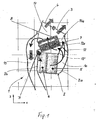
- Fig. 1 shows an air conditioner 1, shown as a section in the xz plane of a motor vehicle, not shown, wherein the x-direction corresponds to the direction of travel.
- the air conditioner 1 is installed from the front under the instrument panel of the vehicle, not shown, and has a housing 2 with a ventilation outlet 3 and a disc defroster outlet 4.
- an evaporator 5 is arranged in the lower region, which optionally a filter 6 can be connected upstream.
- a radiator 7 is arranged, which optionally an electric booster heater 8 may be connected downstream.
- the housing 2 has a housing wall 2a which is rear in the x-direction and a housing wall 2b which is located at the front in the direction of travel.
- a mixing flap 12 is pivotally mounted about an axis 12 a, which extends parallel (perpendicular to the plane of the drawing) to a longitudinal edge of the radiator 7.
- the mixing flap 12 is divided in three in the direction of the pivot axis 12a, ie it consists of three flaps arranged next to each other, which will be explained in connection with FIG.
- the mixing flap 12 is pivotable between the one extreme position 12 (cold air duct 10 closed) and the other extreme position 12 '(cold air duct 10 open).
- the cold air duct 10 continues behind the mixing flap 12 as cold air bypass 10 a, which leads into an air mixing chamber 11, which is arranged downstream of the radiator 7.
- From the air mixing chamber 11 branches off a central air outlet duct 13, which is directed at the front side 2b of the housing directed downwards and supplies the rear compartment of the motor vehicle, not shown here, with conditioned air.
- Two further, not visible here air outlet ducts are arranged laterally of the air outlet 13 - as seen from the next figure.
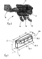
- Fig. 2 shows the air conditioner 1 of FIG. 1 is a perspective view from the front, ie seen against the direction of travel of the vehicle, not shown.
- the same reference numerals as in Fig. 1 are used.
- Laterally of the middle air duct 13, two further air outlet ducts 14, 15 are arranged, which likewise originate from the air mixing chamber 11 and are provided for the air conditioning of the right and left front areas of the vehicle interior, that is to say for the driver side and the passenger side.
- the side of the housing 2 a fan 16 is arranged, which promotes air to be conditioned in the housing (see, air inlet 9 in Fig. 1).
- Fig. 3 shows a section of the air conditioner 1 in the region of the mixing flaps 12, which consists of three mixing flaps 12.1, 12.2, 12.3.
- the detail also shows the evaporator 5 and above, slightly inclined, the radiator 7, ie in an arrangement as shown in Fig. 1.
- the axbox with the axes x, y, z is arranged next to it.
- the three mixing flaps are arranged, pivotable about a common axis 12a, namely two outer mixing flaps 12.1 and 12.2 and a middle mixing flap 12.3, which the central air outlet duct 13 (see.
- Fig. 1 and 2 is assigned.
- the two outer mixing flaps 12.1. and 12.2. are the two outer air outlet channels 15, 14 and the air outlet channels for disc defrost 4 and ventilation 3 assigned. Mixing flaps and air outlet channels are thus arranged in equal parallel planes, so that a two-dimensional air flow - apart from Verwirbelungs binen - results.
- the function of the mixing flaps 12.1, 12.2., 12.3 is an air-side temperature control, d. H.
- the cold air stream cooled by the evaporator 5 and flowing through the cold air duct 10 is either guided through the heating element 7 or passed by the heating element 7 through the bypass duct 10a (see FIG. 1) or through both the radiator 7 and the bypass duct 10a, where various intermediate positions are possible.
- the mixing flaps 12.1., 12.2., 12.3 can be pivoted independently of each other, as desired by the driver or front passenger or the rear passengers, d. H. according to the desired temperature for a zone 1, a zone 2 and a zone 3 in the vehicle interior.
- At different position of the mixing flaps 12.1., 12.2., 12.3 arise in the mixing chamber 11 different temperature air streams, d. H.
Landscapes
- Physics & Mathematics (AREA)
- Thermal Sciences (AREA)
- Engineering & Computer Science (AREA)
- Mechanical Engineering (AREA)
- Air-Conditioning For Vehicles (AREA)
Description
Die Erfindung betrifft eine Klimaanlage für ein Kraftfahrzeug nach dem Oberbegriff des Patentanspruches 1.The invention relates to an air conditioner for a motor vehicle according to the preamble of
Dies wird z.B. in der US 6019 163 gezeigtThis is e.g. in US 6019163
Klimaanlagen für Kraftfahrzeuge in ihrer einfachsten Ausführung - z. B. gemäß DE 100 42 683 - versorgen den gesamten Fahrzeuginnenraum mit klimatisierter Luft gleicher Temperatur. Für höhere Komfortansprüche sind so genannte Rechts/Links-Regelungen bekannt, bei welchen der Bereich um den Fahrer und der Bereich um den Beifahrer, also zwei Zonen, individuell klimatisierbar sind, d. h. mit Luftströmen unterschiedlicher Temperatur. Für größere Fahrzeuge, insbesondere Vans, wurden so genannte Vier-Zonen-Klimatisierungen bekannt, bei welchen der Fahrzeuginnenraum in vier Zonen aufgeteilt ist, welche mit Luft unterschiedlicher Temperatur versorgt werden können. Das Problem besteht meistens darin, einen hinreichenden Klimatisierungskomfort mit geringem Bau- und Kostenaufwand für die Klimaanlage zu erreichen.Air conditioning systems for motor vehicles in their simplest version - z. B. according to DE 100 42 683 - provide the entire vehicle interior with conditioned air at the same temperature. For higher comfort requirements so-called right / left controls are known in which the area around the driver and the area around the passenger, ie two zones, are individually air-conditioned, d. H. with air streams of different temperature. For larger vehicles, especially vans, so-called four-zone air conditioning systems were known in which the vehicle interior is divided into four zones, which can be supplied with air of different temperature. The problem is usually to achieve a sufficient climate comfort with low construction and cost of the air conditioning.
Durch die DE 197 31 908 A1 wurde eine Vier-Zonen-Klimatisierungsanlage bekannt, bei welcher der Luftaustrittsquerschnitt hinter dem Heizkörper durch zwei senkrecht zueinander verlaufende Trennwände in vier quadrantenähnliche Mischräume aufgeteilt ist, von welchen Luftauslasskanäle für unterschiedlich temperierte Luftströme ausgehen. Die Temperaturregelung erfolgt dabei durch Mischung von Kaltluft über Bypass-Kaltluftkanäle und Warmluft mittels Kaltluft- und Warmluftmischklappen. Eine solche Klimaanlage ist relativ aufwendig.DE 197 31 908 A1 has disclosed a four-zone air-conditioning system in which the air outlet cross-section behind the radiator is divided by two mutually perpendicular partitions into four quadrant-like mixing chambers, from which air outlet ducts for differently tempered air streams emerge. The temperature is controlled by mixing cold air through bypass cold air ducts and warm air by means of cold air and warm air mixing flaps. Such air conditioning is relatively expensive.
Durch die DE 197 39 578 A1 wurde eine weitere Vier-Zonen-Klimatisierungsanlage bekannt, bei welcher ein Kaltluftkanal in vier Teilkanäle unterteilt ist, welche durch vier separate Mischklappen kontrolliert werden. Die Mischklappen sind nebeneinander angeordnet und weisen eine gemeinsame Schwenkachse auf, die sich in Längsrichtung des Heizkörpers erstreckt. Durch diese Schwenkklappenanordnung werden in vier separaten Luftmischräumen unterschiedliche temperierte Luftströme erzeugt, die über Luftauslasskanäle den vier Zonen des Fahrzeuginnenraums zuleitbar sind. Auch diese Anlage, von der die Erfindung ausgeht, ist, u. a. wegen der zahlreichen Trennwände und Klappen, ebenfalls sehr aufwendig.From DE 197 39 578 A1, a further four-zone air conditioning system has been disclosed in which a cold air duct is subdivided into four subchannels, which are controlled by four separate mixing flaps. The mixing flaps are arranged side by side and have a common pivot axis which extends in the longitudinal direction of the radiator. By means of this pivoting flap arrangement, different tempered air flows are generated in four separate air mixing chambers, which can be supplied to the four zones of the vehicle interior via air outlet ducts. This system, from which the invention proceeds, u. a. because of the numerous partitions and flaps, also very expensive.
Es ist Aufgabe der vorliegenden Erfindung, eine Klimaanlage der eingangs genannten Art zu vereinfachen, insbesondere kompakt zu gestalten und dennoch einen hinreichenden Klimatisierungskomfort zu bieten.It is an object of the present invention to simplify an air conditioner of the type mentioned above, in particular to make it compact and yet to provide adequate air conditioning comfort.
Diese Aufgabe wird durch die Merkmale des Patentanspruches 1 gelöst. Durch die Anordnung des Heizkörpers oberhalb des Verdampfers wird eine kompakte Bauweise, insbesondere eine in Fahrtrichtung des Kraftfahrzeuges (x-Richtung) verkürzte Klimaanlage bereitgestellt. Dies bringt u. a. ein höheres Raumangebot im Frontbereich des Fahrzeuginnenraums. Darüber hinaus ist die Klimaanlage als Drei-Zonen-Anlage konzipiert und weist somit nur drei nebeneinander angeordnete Mischklappen auf, wodurch drei unterschiedlich temperierte Luftströme erzeugt werden können. Diese gelangen in mehrere, vorzugsweise drei Luftauslasskanäle, über welche sie drei Zonen des Fahrzeuginnenraumes, nämlich vorne links, vorne rechts und dem Fond zuführbar sind. Somit ergibt sich als Vorteil eine kompakte Klimaanlage mit überdurchschnittlichem Komfortangebot.This object is solved by the features of
Nach einer vorteilhaften Ausgestaltung der Erfindung sind die Luftauslasskanäle in Fahrtrichtung vorn liegend am Gehäuse angeordnet, d. h. auf der dem Kaltluftkanal gegenüber liegenden Seite. Dabei ist der mittlere Luftauslasskanal der mittleren Mischklappe zugeordnet und klimatisiert die dritte Zone, d. h. den Fond. Vorzugsweise führt der mittlere Luftauslasskanal von oben nach unten, während die Kaltluft von unten nach oben strömt. Es ergeben sich somit kurze Luftwege mit geringen Umlenkungen und damit geringe luftseitige Druckabfälle. Im Gegensatz zum Stand der Technik benötigt die erfindungsgemäße Klimaanlage keine Trennwände, weder im Kaltluftkanal noch im Luftmischraum. Vielmehr werden die unterschiedlich temperierten Teilluftströme durch Temperaturschichtung eines Hauptluftstromes erzeugt. Dafür ist allerdings eine hinreichende Höhe von Verdampfer und Heizkörper erforderlich, um die drei Mischklappen nebeneinander anzuordnen. Nach einer bevorzugten Ausführungsform ist daher das Verhältnis von Höhe zu Breite sowohl beim Verdampfer als auch beim Heizkörper größer als zwei, vorzugsweise größer als drei.According to an advantageous embodiment of the invention, the air outlet ducts are arranged in front lying on the housing in the direction of travel, ie on the side opposite the cold air duct. Here, the middle air outlet channel of the middle mixing flap is assigned and air conditioned the third Zone, ie the fund. Preferably, the middle Luftauslasskanal leads from top to bottom, while the cold air flows from the bottom upwards. This results in short airways with low deflections and thus low air pressure drops. In contrast to the prior art, the air conditioning system according to the invention requires no partitions, neither in the cold air duct nor in the air mixing chamber. Rather, the different tempered partial air flows are generated by temperature stratification of a main air stream. For this, however, a sufficient amount of evaporator and radiator is required to arrange the three mixing flaps side by side. According to a preferred embodiment, therefore, the ratio of height to width both in the evaporator and the radiator is greater than two, preferably greater than three.
Ein Ausführungsbeispiel der Erfindung ist in der Zeichnung dargestellt und wird im Folgenden näher beschrieben. Es zeigen
- Fig. 1
- einen Schnitt durch das Gehäuse einer Klimaanlage,
- Fig. 2
- eine perspektivische Darstellung der Klimaanlage und
- Fig. 3
- eine perspektivische Darstellung einer Anordnung von Verdampfer und Heizkörper mit Mischklappen.
- Fig. 1
- a section through the housing of an air conditioner,
- Fig. 2
- a perspective view of the air conditioning and
- Fig. 3
- a perspective view of an arrangement of evaporator and radiator with mixing flaps.
Fig. 1 zeigt eine Klimaanlage 1, dargestellt als Schnitt in der x-z-Ebene eines nicht dargestellten Kraftfahrzeuges, wobei die x-Richtung der Fahrtrichtung entspricht. Die Klimaanlage 1 wird von frontseitig unter der nicht dargestellten Instrumententafel des Fahrzeuges eingebaut und weist ein Gehäuse 2 mit einem Belüftungsauslass 3 und einem Scheibendefrosterauslass 4 auf. Innerhalb des Gehäuses 2 ist im unteren Bereich ein Verdampfer 5 angeordnet, dem optional ein Filter 6 vorgeschaltet sein kann. Oberhalb des Verdampfers 5 ist ein Heizkörper 7 angeordnet, dem optional eine elektrische Zusatzheizung 8 nachgeschaltet sein kann. Das Gehäuse 2 weist eine in x-Richtung hintere Gehäusewand 2a und eine in Fahrtrichtung vorne liegende Gehäusewand 2b auf. Innerhalb der Gehäusewand 2b strömt Luft in das Gehäuse 2, welche von einem hier nicht dargestellten Gebläse gefördert wird und durch einen Punkt mit Pfeil 9 dargestellt ist. Zwischen der hinteren Gehäusewand 2a und dem Verdampfer 5 sowie dem Heizkörper 7 sind ein Kaltluftkanal 10 und ein Kaltluftbypass 10a angeordnet. Im Kaltluftkanal 10 ist eine Mischklappe 12 schwenkbar um eine Achse 12a angeordnet, die sich parallel (senkrecht zur Zeichenebene) zu einer Längskante des Heizkörpers 7 erstreckt. Die Mischklappe 12 ist in Richtung der Schwenkachse 12a dreigeteilt, d. h. sie besteht aus drei nebeneinander angeordneten Klappen, was im Zusammenhang mit Fig. 3 erläutert wird. Die Mischklappe 12 ist zwischen der einen Extremstellung 12 (Kaltluftkanal 10 geschlossen) und der anderen Extremstellung 12' (Kaltluftkanal 10 offen) schwenkbar. Der Kaltluftkanal 10 setzt sich hinter der Mischklappe 12 als Kaltluftbypass 10a fort, der in einen Luftmischraum 11 führt, welcher stromabwärts des Heizkörpers 7 angeordnet ist. Vom Luftmischraum 11 zweigt ein mittlerer Luftauslasskanal 13 ab, der an der Vorderseite 2b des Gehäuses nach unten gerichtet verläuft und den hier nicht dargestellten Fondraum des Kraftfahrzeuges mit klimatisierter Luft versorgt. Zwei weitere, hier nicht sichtbare Luftauslasskanäle sind seitlich des Luftauslasskanales 13 angeordnet - wie aus der nächsten Figur erkennbar. Fig. 1 shows an
Fig. 2 zeigt die Klimaanlage 1 gemäß Fig. 1 einer perspektivischen Darstellung von vorn, d. h. entgegen der Fahrtrichtung des nicht dargestellten Fahrzeuges gesehen. Es werden gleiche Bezugszeichen wie in Fig. 1 verwendet. Seitlich des mittleren Luftkanals 13 sind zwei weitere Luftauslasskanäle 14, 15 angeordnet, die ebenfalls vom Luftmischraum 11 ausgehen und für die Klimatisierung des rechten und linken Frontbereiches des Fahrzeuginnenraumes, also für die Fahrer- und für die Beifahrerseite vorgesehen sind. Seitlich des Gehäuses 2 ist ein Gebläse 16 angeordnet, welches zu klimatisierende Luft in das Gehäuse fördert (vgl. Lufteintritt 9 in Fig. 1). Fig. 2 shows the
Fig. 3 zeigt einen Ausschnitt der Klimaanlage 1 im Bereich der Mischklappen 12, die aus drei Mischklappen 12.1, 12..2, 12.3 besteht. Der Ausschnitt zeigt ferner den Verdampfer 5 und darüber, leicht geneigt, den Heizkörper 7, d. h. in einer Anordnung, wie sie in Fig. 1 dargestellt ist. Zur Orientierung ist das Achsenkreuz mit den Achsen x, y, z daneben angeordnet. Am Heizkörper 7 sind, um eine gemeinsame Achse 12a schwenkbar, die drei Mischklappen angeordnet, nämlich zwei äußere Mischklappen 12.1 und 12.2 und eine mittlere Mischklappe 12.3, welche dem mittleren Luftauslasskanal 13 (vgl. Fig. 3 shows a section of the
Fig. 1 und 2) zugeordnet ist. Die beiden äußeren Mischklappen 12.1. und 12.2. sind den beiden äußeren Luftauslasskanälen 15, 14 bzw. den Luftauslasskanälen für Scheibendefrost 4 und Belüftung 3 zugeordnet. Mischklappen und Luftaustrittskanäle sind somit in gleichen parallelen Ebenen angeordnet, sodass sich eine zweidimensionale Luftströmung - abgesehen von Verwirbelungseffekten - ergibt.Fig. 1 and 2) is assigned. The two outer mixing flaps 12.1. and 12.2. are the two outer
Die Funktion der Mischklappen 12.1, 12.2., 12.3 ist eine luftseitige Temperaturregelung, d. h. der vom Verdampfer 5 abgekühlte, durch den Kaltluftkanal 10 strömende Kaltluftstrom wird entweder durch den Heizkörper 7 geführt oder an dem Heizkörper 7 durch den Bypasskanal 10a vorbeileitet (vgl. Fig. 1) oder sowohl durch den Heizkörper 7 als auch durch den Bypasskanal 10a geleitet, wobei diverse Zwischenstellungen möglich sind. Die Mischklappen 12.1., 12.2., 12.3 können unabhängig voneinander verschwenkt werden, je nach Wunsch des Fahrers oder Beifahrers oder der Fondpassagiere, d. h. entsprechend der gewünschten Temperatur für eine Zone 1, eine Zone 2 und eine Zone 3 im Fahrzeuginnenraum. Bei unterschiedlicher Stellung der Mischklappen 12.1., 12.2., 12.3 entstehen im Mischraum 11 unterschiedlich temperierte Luftteilströme, d. h. ein Luftstrom mit einer Temperaturschichtung in y-Richtung. Ist beispielsweise die Mischklappe 12.3 geschlossen (Stellung 12' in Fig. 1), während die äußeren Mischklappen 12.1., 12.2 offen sind (Stellung 12 in Fig. 1), dann wird die Zone 3, also der Fondraum mit Kaltluft versorgt, während in den Frontbereich rechts und links Warmluft einströmt. Damit keine Durchmischung der Teilluftströme in y-Richtung und damit eine Temperaturangleichung erfolgt, müssen Verdampfer 5 und Heizkörper 7 eine relativ große Höhe H aufweisen, d. h. eine Erstreckung in y-Richtung. Das Verhältnis von Höhe H zu Breite B soll dabei über dem Wert 2, vorzugsweise 3 liegen, sodass der Heizkörper 7 mindestens doppelt bzw. dreimal so hoch wie breit ist.The function of the mixing flaps 12.1, 12.2., 12.3 is an air-side temperature control, d. H. the cold air stream cooled by the
Die Luftströmung innerhalb der Klimaanlage (dargestellt durch Pfeile in Fig. 1) erfolgt ohne starke Umlenkungen und folgt etwa, ausgehend vom Lufteintritt 9 in Fig. 1, dem Verlauf einer Spirale: Vom Verdampfer 5 über den Kaltluftkanal 10 durch den Heizkörper 7 und/oder durch den Bypass 10a, durch den Mischraum 11 bis in die Luftauslasskanäle 13, 14, 15. Dies bedeutet neben einer kompakten Bauweise einen relativ geringen luftseitigen Druckverlust. The air flow within the air conditioning system (represented by arrows in Fig. 1) without strong deflections and follows approximately, starting from the
Claims (6)
- An air conditioning system for a motor vehicle having a housing (2) which has an evaporator (5), a heating element (7), a cold air duct (10) with bypass (10a), mixer flaps (12) and air outlet ducts, the mixer flaps (12) being positioned adjacent to one another in the cold air duct (10) such that they are able to pivot about an axis (12a) and generating air flows of different temperatures which can be supplied to different zones of the motor vehicle by the air outlet ducts, the heating element (7) being positioned above the evaporator (5) when the air conditioning system (1) is fitted in the motor vehicle,
characterised in that
three mixer flaps (12.1, 12.2, 12.3) which are assigned to various air outlet ducts (3, 4, 13, 14, 15) are provided. - An air conditioning system in accordance with claim 1,
characterised in that
the mixer flaps (12.1, 12.2, 12.3) can be pivoted about a common axis (12a) or about axes which are positioned parallel to one another. - An air conditioning system in accordance with claim 1 or 2,
characterised in that
the air outlet ducts (13, 14, 15) are positioned adjacent to one another and on the side of the housing (2) opposite the cold air duct (10) (at the front in the direction of movement), and the central air outlet duct (13) is assigned to the central mixer flap (12.3). - An air conditioning system in accordance with claim 3,
characterised in that
positioned downstream of and above the heating element (7) and the cold air duct (10a) is an air mixing chamber (11) from which lead the air outlet ducts (13, 14, 15). - An air conditioning system in accordance with claim 3 or 4,
characterised in that
the central air outlet duct (13) and is positioned running from top to bottom. - An air conditioning system in accordance with one of the claims 1 to 5,
characterised in that
the evaporator (5) and the heating element (7) are of height (H) running in the direction of the axis of pivoting (12a) of the mixer flaps (12.1, 12.2, 12.3) and of width (B), H > 2 B, preferably H > 3 B.
Priority Applications (3)
| Application Number | Priority Date | Filing Date | Title |
|---|---|---|---|
| EP20030292199 EP1512562B1 (en) | 2003-09-05 | 2003-09-05 | Vehicle air conditioning system |
| DE50305047T DE50305047D1 (en) | 2003-09-05 | 2003-09-05 | Air conditioning for a motor vehicle |
| ES03292199T ES2272923T3 (en) | 2003-09-05 | 2003-09-05 | AIR CONDITIONING INSTALLATION FOR MOTOR VEHICLE. |
Applications Claiming Priority (1)
| Application Number | Priority Date | Filing Date | Title |
|---|---|---|---|
| EP20030292199 EP1512562B1 (en) | 2003-09-05 | 2003-09-05 | Vehicle air conditioning system |
Publications (2)
| Publication Number | Publication Date |
|---|---|
| EP1512562A1 EP1512562A1 (en) | 2005-03-09 |
| EP1512562B1 true EP1512562B1 (en) | 2006-09-13 |
Family
ID=34130367
Family Applications (1)
| Application Number | Title | Priority Date | Filing Date |
|---|---|---|---|
| EP20030292199 Expired - Lifetime EP1512562B1 (en) | 2003-09-05 | 2003-09-05 | Vehicle air conditioning system |
Country Status (3)
| Country | Link |
|---|---|
| EP (1) | EP1512562B1 (en) |
| DE (1) | DE50305047D1 (en) |
| ES (1) | ES2272923T3 (en) |
Family Cites Families (6)
| Publication number | Priority date | Publication date | Assignee | Title |
|---|---|---|---|---|
| DE19731908B4 (en) | 1997-07-24 | 2006-06-08 | Behr Gmbh & Co. Kg | Heating and air conditioning for a motor vehicle |
| DE19739578C2 (en) | 1997-09-10 | 2000-03-02 | Behr Gmbh & Co | Heating or air conditioning for a motor vehicle |
| JP3858466B2 (en) * | 1997-09-25 | 2006-12-13 | 株式会社デンソー | Automotive air conditioner |
| US6453991B1 (en) * | 1999-03-29 | 2002-09-24 | Calsonickansei Corporation | Automotive air conditioner |
| DE10042683A1 (en) | 2000-08-31 | 2002-03-14 | Behr Gmbh & Co | Air conditioning unit for motor vehicles has two housing sections ate 90o to each other, and connected via flow channel connector |
| DE10158956B4 (en) * | 2001-12-03 | 2006-03-16 | Webasto Ag | System for heating and cooling a passenger compartment of a vehicle |
-
2003
- 2003-09-05 EP EP20030292199 patent/EP1512562B1/en not_active Expired - Lifetime
- 2003-09-05 DE DE50305047T patent/DE50305047D1/en not_active Expired - Lifetime
- 2003-09-05 ES ES03292199T patent/ES2272923T3/en not_active Expired - Lifetime
Also Published As
| Publication number | Publication date |
|---|---|
| EP1512562A1 (en) | 2005-03-09 |
| DE50305047D1 (en) | 2006-10-26 |
| ES2272923T3 (en) | 2007-05-01 |
Similar Documents
| Publication | Publication Date | Title |
|---|---|---|
| DE10037384B4 (en) | Heating and air conditioning for a motor vehicle | |
| DE3714820A1 (en) | AIR DISCHARGE DEVICE OF A HEATING AND / OR AIR CONDITIONING, IN PARTICULAR FOR THE REAR SPACE OF A PERSONAL VEHICLE | |
| DE102004033402B4 (en) | Modular system for the construction of a 1-zone to 4-zone air conditioning system for vehicles | |
| DE102004033856B4 (en) | Air conditioning for vehicles | |
| WO2005063517A1 (en) | Multi-zone air conditioning system for a motor vehicle | |
| DE3046336A1 (en) | VEHICLE AIR CONDITIONING | |
| DE102014002419A1 (en) | Vehicle air conditioning | |
| EP1228907B1 (en) | Air conditioning device for a motor vehicle | |
| DE102009044760B4 (en) | Air conditioning for a motor vehicle | |
| EP1641642B1 (en) | Air-conditioning system | |
| DE19747646B4 (en) | Air distribution device for a vehicle | |
| DE10147112A1 (en) | Regulator flap e.g. for air conditioning and ventilation appliance for motor vehicles has two wings each with flat sides and associated guide element to define flow gap | |
| DE102007013432B4 (en) | Warm air duct for an air conditioner of a motor vehicle | |
| DE19923189C1 (en) | Air-conditioning installation for automobile rear passenger space uses evaporator and heat exchanger behind each front seat and fan positioned between front passenger seats | |
| DE19639321C1 (en) | Air conditioning plant for vehicle interior | |
| DE10147113A1 (en) | Air conditioning and ventilation device for motor vehicles has channel element to feed part hot air flow from area with hot air concentration, to defroster outlet | |
| DE10112969B4 (en) | Air conditioning for a motor vehicle | |
| DE102014210264A1 (en) | Air conditioning and air temperature control | |
| EP1512562B1 (en) | Vehicle air conditioning system | |
| DE102007049340A1 (en) | Motor vehicle air conditioning arrangement | |
| EP1636056B1 (en) | Assembly arrangement for an air conditioning unit | |
| DE10045438A1 (en) | Air conditioning for a motor vehicle | |
| WO2005084973A1 (en) | Air-conditioning device, in particular for a motor vehicle | |
| EP1741581B1 (en) | Rear ventilating, heating or cooling system | |
| DE9214638U1 (en) | Ventilation system for vehicles |
Legal Events
| Date | Code | Title | Description |
|---|---|---|---|
| PUAI | Public reference made under article 153(3) epc to a published international application that has entered the european phase |
Free format text: ORIGINAL CODE: 0009012 |
|
| AK | Designated contracting states |
Kind code of ref document: A1 Designated state(s): AT BE BG CH CY CZ DE DK EE ES FI FR GB GR HU IE IT LI LU MC NL PT RO SE SI SK TR |
|
| AX | Request for extension of the european patent |
Extension state: AL LT LV MK |
|
| RAP1 | Party data changed (applicant data changed or rights of an application transferred) |
Owner name: BEHR FRANCE ROUFFACH SAS |
|
| 17P | Request for examination filed |
Effective date: 20050909 |
|
| AKX | Designation fees paid |
Designated state(s): CZ DE ES FR GB IT |
|
| GRAP | Despatch of communication of intention to grant a patent |
Free format text: ORIGINAL CODE: EPIDOSNIGR1 |
|
| GRAS | Grant fee paid |
Free format text: ORIGINAL CODE: EPIDOSNIGR3 |
|
| GRAA | (expected) grant |
Free format text: ORIGINAL CODE: 0009210 |
|
| AK | Designated contracting states |
Kind code of ref document: B1 Designated state(s): CZ DE ES FR GB IT |
|
| REG | Reference to a national code |
Ref country code: GB Ref legal event code: FG4D Free format text: NOT ENGLISH |
|
| REF | Corresponds to: |
Ref document number: 50305047 Country of ref document: DE Date of ref document: 20061026 Kind code of ref document: P |
|
| GBT | Gb: translation of ep patent filed (gb section 77(6)(a)/1977) |
Effective date: 20061101 |
|
| ET | Fr: translation filed | ||
| REG | Reference to a national code |
Ref country code: ES Ref legal event code: FG2A Ref document number: 2272923 Country of ref document: ES Kind code of ref document: T3 |
|
| PLBE | No opposition filed within time limit |
Free format text: ORIGINAL CODE: 0009261 |
|
| STAA | Information on the status of an ep patent application or granted ep patent |
Free format text: STATUS: NO OPPOSITION FILED WITHIN TIME LIMIT |
|
| 26N | No opposition filed |
Effective date: 20070614 |
|
| PGFP | Annual fee paid to national office [announced via postgrant information from national office to epo] |
Ref country code: ES Payment date: 20070926 Year of fee payment: 5 |
|
| PGFP | Annual fee paid to national office [announced via postgrant information from national office to epo] |
Ref country code: CZ Payment date: 20070905 Year of fee payment: 5 |
|
| PGFP | Annual fee paid to national office [announced via postgrant information from national office to epo] |
Ref country code: IT Payment date: 20070919 Year of fee payment: 5 |
|
| PG25 | Lapsed in a contracting state [announced via postgrant information from national office to epo] |
Ref country code: CZ Free format text: LAPSE BECAUSE OF NON-PAYMENT OF DUE FEES Effective date: 20080905 |
|
| PG25 | Lapsed in a contracting state [announced via postgrant information from national office to epo] |
Ref country code: IT Free format text: LAPSE BECAUSE OF NON-PAYMENT OF DUE FEES Effective date: 20080905 |
|
| REG | Reference to a national code |
Ref country code: ES Ref legal event code: FD2A Effective date: 20080906 |
|
| PG25 | Lapsed in a contracting state [announced via postgrant information from national office to epo] |
Ref country code: ES Free format text: LAPSE BECAUSE OF NON-PAYMENT OF DUE FEES Effective date: 20080906 |
|
| PGFP | Annual fee paid to national office [announced via postgrant information from national office to epo] |
Ref country code: FR Payment date: 20101005 Year of fee payment: 8 |
|
| PGFP | Annual fee paid to national office [announced via postgrant information from national office to epo] |
Ref country code: GB Payment date: 20100929 Year of fee payment: 8 |
|
| PGFP | Annual fee paid to national office [announced via postgrant information from national office to epo] |
Ref country code: DE Payment date: 20101025 Year of fee payment: 8 |
|
| GBPC | Gb: european patent ceased through non-payment of renewal fee |
Effective date: 20110905 |
|
| REG | Reference to a national code |
Ref country code: FR Ref legal event code: ST Effective date: 20120531 |
|
| REG | Reference to a national code |
Ref country code: DE Ref legal event code: R119 Ref document number: 50305047 Country of ref document: DE Effective date: 20120403 |
|
| PG25 | Lapsed in a contracting state [announced via postgrant information from national office to epo] |
Ref country code: DE Free format text: LAPSE BECAUSE OF NON-PAYMENT OF DUE FEES Effective date: 20120403 |
|
| PG25 | Lapsed in a contracting state [announced via postgrant information from national office to epo] |
Ref country code: FR Free format text: LAPSE BECAUSE OF NON-PAYMENT OF DUE FEES Effective date: 20110930 Ref country code: GB Free format text: LAPSE BECAUSE OF NON-PAYMENT OF DUE FEES Effective date: 20110905 |