EP1512339A1 - Zuglasche für Reissverschlussschieber - Google Patents
Zuglasche für Reissverschlussschieber Download PDFInfo
- Publication number
- EP1512339A1 EP1512339A1 EP04254957A EP04254957A EP1512339A1 EP 1512339 A1 EP1512339 A1 EP 1512339A1 EP 04254957 A EP04254957 A EP 04254957A EP 04254957 A EP04254957 A EP 04254957A EP 1512339 A1 EP1512339 A1 EP 1512339A1
- Authority
- EP
- European Patent Office
- Prior art keywords
- insert portion
- pull tab
- cover
- slide fastener
- surface features
- Prior art date
- Legal status (The legal status is an assumption and is not a legal conclusion. Google has not performed a legal analysis and makes no representation as to the accuracy of the status listed.)
- Granted
Links
Images






Classifications
-
- A—HUMAN NECESSITIES
- A44—HABERDASHERY; JEWELLERY
- A44B—BUTTONS, PINS, BUCKLES, SLIDE FASTENERS, OR THE LIKE
- A44B19/00—Slide fasteners
- A44B19/24—Details
- A44B19/26—Sliders
-
- A—HUMAN NECESSITIES
- A44—HABERDASHERY; JEWELLERY
- A44B—BUTTONS, PINS, BUCKLES, SLIDE FASTENERS, OR THE LIKE
- A44B19/00—Slide fasteners
- A44B19/24—Details
- A44B19/26—Sliders
- A44B19/262—Pull members; Ornamental attachments for sliders
-
- Y—GENERAL TAGGING OF NEW TECHNOLOGICAL DEVELOPMENTS; GENERAL TAGGING OF CROSS-SECTIONAL TECHNOLOGIES SPANNING OVER SEVERAL SECTIONS OF THE IPC; TECHNICAL SUBJECTS COVERED BY FORMER USPC CROSS-REFERENCE ART COLLECTIONS [XRACs] AND DIGESTS
- Y10—TECHNICAL SUBJECTS COVERED BY FORMER USPC
- Y10T—TECHNICAL SUBJECTS COVERED BY FORMER US CLASSIFICATION
- Y10T24/00—Buckles, buttons, clasps, etc.
- Y10T24/25—Zipper or required component thereof
- Y10T24/2561—Slider having specific configuration, construction, adaptation, or material
- Y10T24/2586—Slider having specific configuration, construction, adaptation, or material including pull tab attaching means
Definitions
- This invention relates to a pull tab of a slide fastener slider, and specifically to a pull tab which is comprised of a pull tab proper and a cover to cover the pull tab proper.
- the pull tab 100 of this U. S. patent comprises a pull tab proper 102 and an attachment 104 functioning as a cover.
- the pull tab proper 102 has a locking hole 106 formed at the distal end thereof and a locking projection 108 formed beside the locking hole 106.
- the attachment 104 is comprised of an attachment body 110 and a U-shaped clip 114.
- the attachment body 110 is molded from polyurethane, silicon rubber, thermoplastic elastomer, and has a channel 112 formed longitudinally thereof.
- the U-shaped clip 114 has its bottom end embedded in the channel 112 of the attachment body 110 and has a locking tongue 118 directed inwardly of the channel 112.
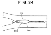
- the pull tab 200 of this Japanese publication is comprised of a pull tab proper 202 and a sheath 204 adapted to wrap around the pull tab proper 202.
- the pull tab proper 202 is of a cigar-like smooth rounded shape and has a thin front end, a thick middle part and a thin rear end, if named from left to right in Figure 34.
- the sheath 204 is molded from polyurethane, silicon rubber, or thermoplastic elastomer.
- the pull tab proper 202 is covered with the sheath 204 to provide a pleasing touch.
- the pull tab 100 shown in Figure 33 is comprised of the pull tab proper 102 and the attachment 104 which in turn is comprised of the attachment body 110 and the clip 114. This means that production of the attachment 104 requires an extra step of assembling the clip 114 with the attachment body 110. Thus, the production of the attachment 104 and hence the pull tab 100 as a whole takes more labor and more time.
- pull tab proper 202 of the pull tab 200 shown in Figure 34 has a cigar-like streamlined smooth rounded shape; during the manipulation of the pull tab 200, the flexible and resilient sheath 204 wrapped around the pull tab body 202 tends to slip off the pull tab body 202 at great ease.
- a pull tab of a slide fastener slider which is comprised of a pull tab proper and a cover, wherein the pull tab proper is adapted to be inserted into the cover which is flexible and agreeable to the touch and wherein, once the pull tab proper is inserted into the cover, the cover can be retained on the pull tab body stably and firmly for a prolonged period of term.
- a pull tab of a slide fastener slider comprises: a pull tab proper having a insert portion and a slider-attaching portion provided at a proximal end of the insert portion for attachment to the slider; and a cover made of flexible material and adapted to have the insert portion inserted thereinto.
- the insert portion includes a plurality of locking surface features.
- a pull tab for a slide fastener slider is comprised of a pull tab proper 1 and a cover 2.
- the pull tab proper 1 is diecasted from metals such as aluminum alloy, zink alloy and the like.
- the pull tab proper 1 comprises an insert portion 6 and a slider-attaching portion or attaching link 5 provided at a proximal end of the insert portion 6 for attachment to a slider body 30.
- the insert portion 6 is provided with various locking surface features 10 such as projections 11, serrates 13, ridges or ridges 17, a flared portion 18, through holes 14, recesses 15, notches or indentations 16, and any combination of these locking surface features 10.
- the cover 2 is injection-molded from polyurethane, silicon rubber, thermoplastic elastomer or the like.
- the cover 2 has a channel 22 formed longitudinally thereof to house the insert portion 6 therein, and locked surface features 21 formed in the inner surface of the channel 22 and adapted for locking engagement with the locking surface features 10 on the insert portion 6.
- some of the locking surface features 10 merely presses and bites into the inner surface of the channel 22, to thus firmly grasp the cover 2 and prevent the cover 2 from being pulled off or dislodged from the pull tab proper 1.
- Figures 1 through 10 shows a pull tab of a slide fastener slider according to the first embodiment of this invention.
- the pull tab proper 1 comprises the insert portion 6 and the slider-attaching portion 5 provided on the proximal end of the insert portion 6.
- the pull tab proper 1 is pivotally mounted on the slider body 30 by linking the slider-attaching portion 5 of the pull tab proper 1 to a pull-tab-attaching lug 31 mounted on the slider body 30.
- the insert portion 6 is an elongated flat piece and has a plurality of (two here) through holes 14 formed therethrough. The through holes 14 are aligned with and spaced from each other along the length of the insert portion 6.
- the two through holes 14 are different in their shapes, one which is close to the distal end of the insert portion 6 is oblong and the other which is remote therefrom is trapezoidal.
- Two elongate projections 11 are formed on each of the upper and lower side of the insert portion 6 and extend laterally of the length of the insert portion 6 along that edge of each through hole 14 which is closer to the distal end of the insert portion 6.
- the insert portion 6 is slightly spread or flared outwardly adjacent to its distal end and terminates in an arcuate end to thus provide an arcuate flared portion 18.
- the two through holes 14, the four projections 11 and the arcuate flared or bulged portion 18 constitute the locking surface features 10 to lock the insert portion 6 to the cover 2 against being pulled thereoff when the insert portion 6 is fully inserted into the cover 2.
- the cover 2 has the channel 22 formed longitudinally of the cover 2, in order to permit the insert portion 6 to be inserted thereinto.
- the channel 22 is substantially complementary in shape with the insert portion 6 of the pull tab proper 1.
- Reference numeral 20 denotes an orifice or entrance formed at an open end of the channel 22, through which orifice the insert portion 6 is inserted into the channel 22.
- the inner surface of either top or bottom wall of the channel 22 is flat; while that of the other wall is provided with protuberant engaging lugs 23, which are complementary in shape with the oblong and trapezoidal through holes 14 formed in the insert portion 6.
- the channel 22 and the engaging lugs 23 constitute locked surface features 21 to lock the insert portion 6 to the cover 2 against being pulled thereoff.
- the inner surfaces of both top and bottom walls of the channel 22 may be provided with engaging lugs 23.
- the arcuate flared portion 18 of the insert portion 6 and the projections 11 provided on the both sides of the insert portion 6 wedge through the orifice 20 into the channel 22 by gradually widening the orifice 20 through elastic deformation of the orifice 20.
- the insert portion 6 continues to advance into the channel 22 until the through holes 14 formed in the insert portion 6 reach the respective engaging lugs 23 of the channel 22,. whereupon the engaging lugs 23 comes into fitting engagement with the corresponding through holes 14, as shown in Figures 9 and 10.
- the locking surface features 10 comprised of the projections 11, the flared portion 18 and the through holes 14 and the locked surface features 21 comprised of the channel 22 and the engaging lugs 23 jointly function to entirely prevent the insert portion 6 of the pull tab proper 1 from being pulled off the cover 2.
- the through holes 14 may be circular, rectangular, triangular or of any other suitable shapes.
- the flared portion 18 may be rectangular, rather than being arcuate.
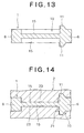
- Figures 11 through 14 shows a pull tab of a slide fastener slider according to the second embodiment of the present invention.
- the pull tab according to the second embodiment is substantially identical with that according to the first embodiment with the following exception.
- the insert portion 6 has the two through holes 14 formed therethrough, one oblong and the other trapezoidal.
- the through holes 14 are aligned with and spaced from each other along the length of the insert portion 6.
- the insert portion 6 instead of the two through holes 14, one oblong and the other trapezoidal formed through the insert portion 6, the insert portion 6 has two pairs in all of oblong and trapezoidal recesses 15 formed one pair on each side thereof, the oblong and trapezoidal recesses of both pairs formed on the upper and lower sides of the insert portion 6 being equal in their outlines and disposed in registry with each other perpendicularly of the insert portion 6.
- the projections 11, the flared portion 18 and the upper and lower recesses 15 of the insert potion 6 constitute the locking surface features 10.
- both inner surfaces of the top and bottom walls of the channel 22 is flat; while the inner surface of the other wall is provided with engaging lugs 23 which are substantially complementary in shape with the oblong and trapezoidal through holes 14.
- both inner surfaces of the top and bottom walls of the channel 22 are provided with engaging lugs 23 functioning as a locked surface features 21.
- the engaging lugs 23 formed in the inner surfaces of the top and bottom walls of the channel 22 are substantially complementary in shape with the oblong and trapezoidal recesses 15 formed in the upper and lower surfaces, respectively, of the insert portion 6.
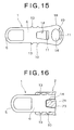
- Figures 15 and 16 show a pull tab of a slide fastener slider according to the third embodiment of the present invention.
- the pull tab according to the third embodiment is substantially identical with that according to the first embodiment, except that the insert portion 6 has a plurality of (two here) serrates or teeth 13, 13 formed on each side edge thereof so as to be separated from each other along the length of the insert portion 6.
- Each serrate 13 is substantially trapezoidal and has that side closer to the connecting link 5 formed perpendicular to the length of the pull tab proper 1 and that side closer to the flared portion 18 formed slant to the length of the pull tab proper 1.
- the through holes 14, the projections 11, the serrates 13 constitute the locking surface features 10.
- the oblong and trapezoidal through holes 14 of the insert portion 6 come into fitting engagement with the engaging lugs 23 of the top and bottom walls of the channel 22, the flared portion 18 is firmly enclosed by the innermost part 22' of the channel 22 and the projections 11 formed along the through openings 14 press against and bite into the inner surface of the top and bottom walls of the channel 22 of the cover 2. Furthermore, the serrates 13 press against and bite into the inside surface of the lateral walls of the channel 22 of the cover 2, so that the insert portion 6 of the pull tab proper 1 is entirely prevent, from being pulled off the cover 2.
- Figures 17 through 22 show a pull tab of a slide fastener slider according to the fourth embodiment of the present invention.
- the pull tab according to the fourth embodiment is substantially identical with that according to the first embodiment, except that the insert portion 6 slightly tapers off toward the distal end thereof and that the insert portion 6 has a plurality of serrate-like notches 16 formed along each side edge thereof and disposed in corresponding positions where those are formed along the other side edge, so that the insert portion 6 is narrowed locally or in the opposed notches 16, in other words, the insert portion 6 has alternate widened regions and narrowed regions along the length thereof.
- Each notch 16 is shaped like a serrate and has the side closer to the distal end of the insert portion 6 formed perpendicular to the length of the insert portion 6 and the side closer to the attaching link 5 formed slant to the length of the insert portion 6.
- An elongated projection 11 is formed on either upper or lower side on each widened regions of the insert portion 6, as shown in Figures 17 and 18.
- the elongated projection 11 is of trapezoidal cross-section and has that side closer to the attaching link 5 formed perpendicular to the general plane of the insert portion 6 and that side closer to the distal end of the insert portion 6 formed slant to the general plane of the insert portion 6.
- the elongated projections 11, notches 16 constitute the locking surface features 10.
- the cover 2 is rectangular in cross-section taken along the general plane of the cover 2, is of a cigar-like shape in cross-section taken perpendicular of the general plane of the cover 2 as shown in Figure 20.
- the cover 2 has formed longitudinally thereof a channel 22 which is complementary in shape with the insert portion 6 of the pull tab proper 1 shown in Figure 17.
- the cover 2 also has a plurality of engaging lugs 23 formed on each side wall of the channel 22 which are complementary in shape with and adapted for coming into fitting engagement with the notches 16 of the insert portion 6.
- the inner surfaces of the top and bottom walls of the channel 22 of the cover 2 are formed flat as shown in Figure 20.
- the insert portion 6 of the pull tab proper 1 For inserting the insert portion 6 of the pull tab proper 1 into the channel 22 of the cover 2, the insert portion 6 is forced through the orifice 20 through elastic deformation of the orifice 20 into the channel 22 of the cover 2 until the insert portion 6 is fully inserted into the channel 22 of the cover 2, whereupon the notches 16 of the insert portion 6 come into fitting engagement with the engaging lugs 23 as shown in Figure 21 and the elongated projections 11 on both upper and lower sides of the insert portion 6 press against and bite into the flat inner surface of the top and bottom walls of the channel 22 of the cover 2 as shown in Figure 22, so that the cover 2 is fully prevented from being pulled off the insert portion 6 of the pull tab proper 1.
- Figures 23 through 25 shows a pull tab of a slide fastener slider according to the fifth embodiment of the present invention.
- the pull tab according to the fifth embodiment is substantially identical with that according to the fourth embodiment shown in Figures 17 through 22 with the following exceptions.
- the pull tab proper 1 has an attaching portion or attaching link 5 which is ring-shaped or loop-shaped formed at its proximal end and the attaching portion 5 itself is directly connected to the pull-tab-attaching lug 31 provided on the upper surface of the slider body 30.
- the pull tab according to the fifth embodiment has a U-shaped clamper 5' formed at its proximal end and the U-shaped clamper 5' is adapted to clamp a connection ring (not shown) which is in turn attached to the pull-tab-attachment lug 31 on the slider body 30.
- the insert portion 6 of the pull tab proper 1 according to this embodiment has the shape of a flattened ellipsoid or flattened football, as shown in Figure 23 and has an oblong cross-section as shown in Figure 24.
- the streamlined insert portion 6 has a plurality of notches 16 formed on both upper and lower sides thereof. Each notch 16 has the side closer to the distal end of the insert portion 6 formed perpendicular to the general plane of the insert portion 6 and the side closer to the clamper 5' formed slant thereto.
- the cover 2 has the shape of a flattened ellipsoid as well and has a channel 22 formed longitudinally thereof which channel 22 is complementary in shape with the flattened ellipsoidal insert portion 6 of the pull tab proper 1.
- the cover 2 has a plurality of protuberant protuberant engaging lugs 23 formed on both top and bottom walls of the channel 22 thereof.
- Figure 26 shows a pull tab proper 1 according to the sixth embodiment of the present invention.
- the pull tab proper 1 according to the sixth embodiment is substantially identical with that according to the first embodiment.
- the pull tab proper 1 has only one through hole 14 formed through the flared end portion 18 and only one pair of projections 11 formed along the periphery of the through hole 10 one on each of the upper and lower surfaces of the insert portion 6.
- the cover 2 according to this embodiment is not shown, the cover 2 has only one protuberant engaging lug 23 formed on the inner surface of either top or bottom wall of the channel 22 thereof.
- the protuberant engaging lug 23 is substantially complementary in shape with the through hole 10 of the insert portion 6 of the pull tab proper 1.
- the projections 11, the through hole 14 and the flared end portion 18 of the insert portion 6 as locking surface features 10 and the channel 22 and the protuberant engaging lugs 23 of the cover 2 as locked surface features 21 coact together to prevent the cover 2 from being pulled off the insert portion 6 of the pull tab proper 1, once the former is fully inserted into the latter.
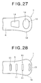
- Figure 27 shows a pull tab proper 1 according to the seventh embodiment of the present invention.
- the pull tab proper 1 according to the seventh embodiment is substantially identical with that according to the first embodiment except that the pull tab proper 1 has no projections in the insert portion 6.
- the through holes 14 and the flared end portion 18 as locking surface features 10 and the channel 22 and the protuberant engaging lugs 23 as locked surface features 21 coact together to prevent the cover 2 from being pulled off the insert portion 6 of the pull tab proper 1, when the former is fully inserted into the latter.
- Figure 28 shows a pull tab proper 1 according to the eighth embodiment of the present invention.
- the pull tab proper 1 has a plurality of elongated projections 11 (four projections shown in Figure 28) formed on each top and bottom side thereof, each extending laterally of the length thereof.
- the elongated projections 11 are disposed in spaced parallel relation to each other longitudinally of the pull tab proper 1.
- Each elongated projection 11 has that side closer to the attaching portion 5 formed perpendicular to the general plane of the pull tab proper 1 and that side closer to the distal end of the insert portion 6 formed slant to the general plane of pull tab proper 1.
- the elongated projections 11 constitute the locking surface features 10 to prevent the cover 2 from being pulled off the insert portion 6 of the pull tab proper 1.
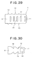
- FIG. 29 shows a pull tab proper 1 according to the ninth embodiment of the present invention.
- the pull tab proper 1 according to the ninth embodiment is substantially identical with that according to the eighth embodiment except that the insert portion 6 of the pull tab proper 1 has a substantially rectangular outline, that is, the insert portion 6 has no flared portion at its distal end and that, in addition to the elongated projections 11 formed on the upper and lower surfaces of the insert portion 6, the insert portion 6 has a plurality of serrates 13 formed along each side edge thereof.
- Each serrate 13 has that side closer to the attaching portion 5 formed perpendicularly to the length of the insert portion 6 and that side closer to the distal end of the insert portion 6 formed slant relative to the length of the insert portion 6.
- the elongated projections 11 and the serrates 13 constitute the locking surface features 10 to prevent the cover 2 from being pulled off the insert portion 6 of the pull tab proper 1.
- Figure 30 shows a pull tab proper 1 according to the tenth embodiment of the present invention.
- the pull tab proper 1 according to the tenth embodiment is substantially identical with that according to the fourth embodiment, except that the insert portion 6 has no elongated projections formed on either side thereof and instead the insert portion 6 has a trapezoidal through hole 14 formed in the distal end portion thereof.
- the cover 2 has at least one protuberant engaging lug formed in the inner surface of either top or bottom side of the channel 22 thereof, which protuberant engaging lug is substantially complementary in shape with the trapezoidal through hole 14 and adapted to fitting engagement with the through hole 14.
- the notches 16 and the through hole 14 constitute the locking surface features 10 to prevent the cover 2 from being pulled off the insert portion 6.
- Figure 31 shows a pull tab proper 1 according to the eleventh embodiment of the present invention.
- the pull tab proper 1 according to the eleventh embodiment is substantially identical with that according to the first embodiment shown in Figure 2, except that the insert portion 6 has two pairs of projecting ridges 17 extending longitudinally of the insert portion along either side edge thereof, one projecting ridge (17) of each pair formed on the upper side and the other ridge (17) on the lower side of the insert portion 6.
- the four projections 11 and the arcuate flared portion 18, the four projecting ridges 17 constitute the locking surface features 10 to lock the insert portion 6 to the cover 2 against being pulled off therefrom when the insert portion 6 is inserted into the cover 2.
- the cover 2 according to the eleventh embodiment may be substantially identical in shape with the cover 2 according to the first embodiment shown in Figures 5 and 6 and the cover 2 according to the second embodiment shown in Figure 14.
- the projections 11 press against and bite into the inner surfaces of the top and bottom walls of the channel 22, the through holes 14 come into fitting engagement with the protuberant engaging lugs 23 formed on the inner surfaces of the top and bottom walls of the channel 22 and the flared end portion 18 is snugly wrapped by the channel 22 of the cover 2, so that the cover 2 is well prevented from being displaced in the direction of being pulled off the insert portion 6 of the pull tab proper 1.
- the projecting ridges 17 formed on the side edges of the insert portion 6 press against the inner surfaces of both top and bottom walls of the channel 22 of the cover 2, so that the cover 2 is well prevented from being rotated relative to the pull tab proper 1 even if severe stresses are exerted tending to distort the pull tab proper 1.
- the locking surface features 10 of the pull tab proper 1 according to the eleventh embodiment advantageously functions not only to prevent the cover 2 from being pulled off the pull tab proper 1 but also to prevent the cover 2 from being rotated relative to the pull tab proper 1.
- Figure 32 shows a pull tab proper 1 according to the twelfth embodiment of the present invention.
- the pull tab proper 1 according to the twelfth embodiment is substantially identical with that according to the fourth embodiment shown in Figure 17, except that the insert portion 6 according to the twelfth embodiment further has a plurality of (three here) trapezoidal through holes 14 formed therethrough beside the respective elongated projections 11 except the one formed at the distal end of the insert portion 6 and the trapezoidal through holes 14 are disposed between the opposed notches 16 formed in the opposed side edges of the insert portion 6 and that a plurality of projecting ridges 17 are provided on both top and bottom side of the insert portion 6, along each side edge substantially except for the notches 16.
- the trapezoidal through holes 14, the elongated projections 11, the projecting ridges 17 and the side notches 16 constitute the locking surface features 10 to prevent the cover 2 from being pulled off from the insert portion 6 once the insert portion 6 is inserted into the cover 2.
- the cover according to the twelfth embodiment substantially identical with that according to the fourth embodiment shown in Figures 19 and 20, except that the cover 2 according to the twelfth embodiment has a plurality of protuberant engaging lugs 23 formed on the inner surface of either one of or both top and bottom walls of the channel 22 of the cover 2, which protuberant engaging lugs 23 are substantially complementary in shape with and adapted to come into fitting engagement with the trapezoidal through holes 14 of the insert portion 6 of the pull tab proper 1.
- the notches 16 of the insert portion 6 come into fitting engagement with the protuberant engaging lugs 23 formed on the side edges of the channel 22 and the elongated projections 11 on both upper and lower sides of the insert portion 6 press against and bite into the flat inner surfaces of both top and bottom walls of the channel 22 of the cover 2, and in addition, the trapezoidal through holes 14 of the insert portion 2 comes into fitting engagement with the protuberant engaging lugs 23 formed on the inner surface of either or both of the top and bottom walls of the channel 22 so that the cover 2 is well prevented from being pulled off the insert portion 6 of the pull tab proper 1.
- the locking surface features 10 of the pull tab proper 1 also advantageously functions not only to prevent the cover 2 from being pulled off the pull tab proper 1 but also to prevent the cover 2 from being rotated relative to the pull tab proper 1.
- the locking surfaces features may include any combination of two or more locking surface features that are different in forms from each other, such as the through holes, the projections, the projecting ridges and the side notches.
- the projections 11 and the projecting ridges 17 of the insert portion 6 press against and bite into the flat inner surface of the top and lower walls of the channel 22 of the cover 2, through elastic deformation of the cover 2.
- the inner surface of the top and bottom walls of the channel 22 of the cover 2 may be provided in its corresponding positions with relevant grooves to facilitating the biting into the cover 2 by the projections 11 and projecting ridges 17 of the insert portion 6.
- the locking surface features advantageously function to prevent the cover from being pulled off the pull tab proper.
- the pull tab according to the invention is comprised of only a pull tab proper and a cover, the pull tab proper having the locking surface features formed in itself. Therefore, this pull tab is simple in construction. No extra part is needed to produce this pull tab. No extra labor and time is thus needed.
- the pull tab of the slide fastener slider according to the present invention described hereinbefore finds a wide application to whole types of clothing, and particularly clothing for infants and aged people, and further to bugs, cases and shoes, or the like.
Landscapes
- Slide Fasteners (AREA)
- Closures For Containers (AREA)
- Knives (AREA)
- Purses, Travelling Bags, Baskets, Or Suitcases (AREA)
Applications Claiming Priority (2)
| Application Number | Priority Date | Filing Date | Title |
|---|---|---|---|
| JP2003313043 | 2003-09-04 | ||
| JP2003313043A JP4043424B2 (ja) | 2003-09-04 | 2003-09-04 | スライドファスナー用スライダーの引手 |
Publications (2)
| Publication Number | Publication Date |
|---|---|
| EP1512339A1 true EP1512339A1 (de) | 2005-03-09 |
| EP1512339B1 EP1512339B1 (de) | 2013-04-24 |
Family
ID=34131874
Family Applications (1)
| Application Number | Title | Priority Date | Filing Date |
|---|---|---|---|
| EP04254957.6A Expired - Lifetime EP1512339B1 (de) | 2003-09-04 | 2004-08-18 | Zuglasche für Reissverschlussschieber |
Country Status (7)
| Country | Link |
|---|---|
| US (1) | US7574783B2 (de) |
| EP (1) | EP1512339B1 (de) |
| JP (1) | JP4043424B2 (de) |
| KR (1) | KR100563580B1 (de) |
| CN (1) | CN1245908C (de) |
| ES (1) | ES2417060T3 (de) |
| TW (1) | TWI248797B (de) |
Cited By (1)
| Publication number | Priority date | Publication date | Assignee | Title |
|---|---|---|---|---|
| EP2705769A1 (de) * | 2012-09-07 | 2014-03-12 | Doreen Martens | Betätigungshilfsmittel für einen Reißverschlussschieber |
Families Citing this family (17)
| Publication number | Priority date | Publication date | Assignee | Title |
|---|---|---|---|---|
| US20070124901A1 (en) * | 2005-08-30 | 2007-06-07 | Cyr Terry J | Zipper Pull Latch for Hanging Object |
| US8132433B2 (en) * | 2006-08-21 | 2012-03-13 | Joan Andersen | Protective device for concealing a zipper pull |
| WO2011039870A1 (ja) * | 2009-09-30 | 2011-04-07 | Ykk株式会社 | スライドファスナー用スライダー |
| US8453301B1 (en) * | 2010-07-22 | 2013-06-04 | Patty McCoy | Zipper pull tab retention device |
| US8677574B1 (en) * | 2011-07-20 | 2014-03-25 | Ken Thiessen | Zipper pull extender |
| US9066616B2 (en) | 2010-12-21 | 2015-06-30 | Luxe Link, Llc | Connector assembly for portable hanger |
| US9743723B2 (en) * | 2011-02-11 | 2017-08-29 | Illinois Tool Works Inc. | One-piece zipper puller |
| KR101271268B1 (ko) * | 2012-04-27 | 2013-06-07 | 와이케이케이한국 (주) | 슬라이드 파스너용 슬라이더의 견인 탭 손잡이 |
| WO2014010090A1 (ja) * | 2012-07-13 | 2014-01-16 | Ykk株式会社 | クランパ、スライダー及びスライドファスナー |
| US20140082895A1 (en) * | 2012-09-27 | 2014-03-27 | Jennifer E. Gold | Zipper cover and method |
| KR101282018B1 (ko) * | 2012-10-17 | 2013-07-04 | 와이케이케이한국 (주) | 슬라이드 파스너용 슬라이더의 견인 탭 손잡이 |
| US8931145B1 (en) * | 2013-11-20 | 2015-01-13 | Mei-Lee Liao | Sliding zipper controller |
| WO2020026334A1 (ja) * | 2018-07-31 | 2020-02-06 | Ykk株式会社 | スライドファスナー用のスライダー |
| US11363858B2 (en) * | 2020-04-06 | 2022-06-21 | Airo Importation, Inc. | Waterproof zipper pull system |
| CN216683058U (zh) * | 2021-11-18 | 2022-06-07 | 立兆股份有限公司 | 织带上的塑料制品 |
| US12127637B1 (en) * | 2024-06-18 | 2024-10-29 | Peter L. Levy | Zipper shield |
| KR102845816B1 (ko) * | 2025-07-03 | 2025-08-13 | 주식회사 가스코 | 세탁물의 부자재 보호커버 |
Citations (5)
| Publication number | Priority date | Publication date | Assignee | Title |
|---|---|---|---|---|
| FR1404564A (fr) * | 1964-05-20 | 1965-07-02 | Raymond A | Perfectionnements apportés aux tirettes ou objets analogues |
| US4368562A (en) * | 1980-01-31 | 1983-01-18 | Yoshida Kogyo K. K. | Ornamental attachment for slide fastener sliders |
| US4389758A (en) * | 1980-06-24 | 1983-06-28 | Yoshida Kogyo K.K. | Ornamental attachment for slide fastener sliders |
| US4873750A (en) * | 1988-01-13 | 1989-10-17 | Tracy Richard J | Attachment for slide fastener slider pull tab |
| US20020069494A1 (en) * | 2000-12-12 | 2002-06-13 | Mccrum Russell C. | Zipper pull |
Family Cites Families (11)
| Publication number | Priority date | Publication date | Assignee | Title |
|---|---|---|---|---|
| AU516651B2 (en) * | 1977-05-12 | 1981-06-18 | Yoshida Kogyo K.K. | Ornamental attachment for slide fastener |
| DE7802440U1 (de) * | 1978-01-27 | 1978-07-06 | Jancik Geb. Peine, Rosemarie, 4714 Selm | Betätigungshilfsvorrichtung für einen Reißverschluß |
| FR2453614A1 (fr) * | 1979-04-11 | 1980-11-07 | Eclair Ind | Curseur pour fermeture a glissiere |
| FR2457083A1 (fr) * | 1979-05-23 | 1980-12-19 | Eclair Prestil Sa | Curseur pour fermeture a glissiere, dont la tirette comporte un organe rapporte |
| JPH0245006A (ja) * | 1988-08-02 | 1990-02-15 | Yoshida Kogyo Kk <Ykk> | スライドフアスナー用スライダー |
| JPH0385546U (de) | 1989-12-20 | 1991-08-29 | ||
| US5136758A (en) * | 1990-06-25 | 1992-08-11 | Wilcox James J | Zipper attachment device |
| US6026546A (en) * | 1997-03-28 | 2000-02-22 | Lund & Company | Figurines attached to a zipper |
| US6415482B1 (en) * | 2000-06-23 | 2002-07-09 | Illinois Tool Works Inc. | Attachment for zipper cord |
| JP3733311B2 (ja) * | 2001-10-25 | 2006-01-11 | Ykk株式会社 | スライドファスナー用スライダーの引手 |
| US7043802B2 (en) * | 2003-01-30 | 2006-05-16 | Illinois Tool Works Inc | Zipper pull with whistle |
-
2003
- 2003-09-04 JP JP2003313043A patent/JP4043424B2/ja not_active Expired - Lifetime
-
2004
- 2004-08-16 US US10/919,677 patent/US7574783B2/en not_active Expired - Lifetime
- 2004-08-18 ES ES04254957T patent/ES2417060T3/es not_active Expired - Lifetime
- 2004-08-18 EP EP04254957.6A patent/EP1512339B1/de not_active Expired - Lifetime
- 2004-08-20 TW TW093125244A patent/TWI248797B/zh not_active IP Right Cessation
- 2004-09-01 KR KR1020040069645A patent/KR100563580B1/ko not_active Expired - Lifetime
- 2004-09-02 CN CNB2004100771956A patent/CN1245908C/zh not_active Expired - Lifetime
Patent Citations (5)
| Publication number | Priority date | Publication date | Assignee | Title |
|---|---|---|---|---|
| FR1404564A (fr) * | 1964-05-20 | 1965-07-02 | Raymond A | Perfectionnements apportés aux tirettes ou objets analogues |
| US4368562A (en) * | 1980-01-31 | 1983-01-18 | Yoshida Kogyo K. K. | Ornamental attachment for slide fastener sliders |
| US4389758A (en) * | 1980-06-24 | 1983-06-28 | Yoshida Kogyo K.K. | Ornamental attachment for slide fastener sliders |
| US4873750A (en) * | 1988-01-13 | 1989-10-17 | Tracy Richard J | Attachment for slide fastener slider pull tab |
| US20020069494A1 (en) * | 2000-12-12 | 2002-06-13 | Mccrum Russell C. | Zipper pull |
Cited By (1)
| Publication number | Priority date | Publication date | Assignee | Title |
|---|---|---|---|---|
| EP2705769A1 (de) * | 2012-09-07 | 2014-03-12 | Doreen Martens | Betätigungshilfsmittel für einen Reißverschlussschieber |
Also Published As
| Publication number | Publication date |
|---|---|
| US7574783B2 (en) | 2009-08-18 |
| CN1245908C (zh) | 2006-03-22 |
| KR20050024236A (ko) | 2005-03-10 |
| CN1589694A (zh) | 2005-03-09 |
| EP1512339B1 (de) | 2013-04-24 |
| TWI248797B (en) | 2006-02-11 |
| JP2005080706A (ja) | 2005-03-31 |
| JP4043424B2 (ja) | 2008-02-06 |
| ES2417060T3 (es) | 2013-08-05 |
| KR100563580B1 (ko) | 2006-03-22 |
| TW200520706A (en) | 2005-07-01 |
| HK1069742A1 (en) | 2005-06-03 |
| US20050050698A1 (en) | 2005-03-10 |
Similar Documents
| Publication | Publication Date | Title |
|---|---|---|
| US7574783B2 (en) | Pull tab of slide fastener slider | |
| JPH0510654Y2 (de) | ||
| US7257865B2 (en) | Holder for cord fasteners | |
| JP3733311B2 (ja) | スライドファスナー用スライダーの引手 | |
| EP0204250A1 (de) | Schnalle | |
| JP3844960B2 (ja) | 紐止め具 | |
| JPS6279412U (de) | ||
| CA1079934A (en) | Slider for slide fasteners | |
| US20020062543A1 (en) | Aid for threading a seat belt through a child safety restraint | |
| US7204002B2 (en) | Buckle and baby carrier using the same | |
| EP1166674A1 (de) | Schnalle | |
| US6484728B1 (en) | Hair clip with improved clipping effect | |
| US7117567B1 (en) | Two-part connecting zipper pull | |
| US7293335B2 (en) | Slider for slide fastener | |
| EP1532886B1 (de) | Schieber für einen Reissverschluss | |
| US4704772A (en) | Snap-fit clasp fastener for bags | |
| JPH10234432A (ja) | 紐固定具 | |
| EP1040770B1 (de) | Schieber für Reissverschlüsse | |
| US6647599B2 (en) | Positioning mechanism of a zipper slide | |
| EP0577270A1 (de) | Verschluss | |
| JPH09164007A (ja) | 紐止め具 | |
| US5535492A (en) | Automatic lock sliders for slide fasteners | |
| JPH024090Y2 (de) | ||
| JPS6399861U (de) | ||
| JPS6347286Y2 (de) |
Legal Events
| Date | Code | Title | Description |
|---|---|---|---|
| PUAI | Public reference made under article 153(3) epc to a published international application that has entered the european phase |
Free format text: ORIGINAL CODE: 0009012 |
|
| 17P | Request for examination filed |
Effective date: 20040825 |
|
| AK | Designated contracting states |
Kind code of ref document: A1 Designated state(s): AT BE BG CH CY CZ DE DK EE ES FI FR GB GR HU IE IT LI LU MC NL PL PT RO SE SI SK TR |
|
| AX | Request for extension of the european patent |
Extension state: AL HR LT LV MK |
|
| AKX | Designation fees paid |
Designated state(s): DE ES FR GB IT TR |
|
| 17Q | First examination report despatched |
Effective date: 20070611 |
|
| GRAP | Despatch of communication of intention to grant a patent |
Free format text: ORIGINAL CODE: EPIDOSNIGR1 |
|
| GRAJ | Information related to disapproval of communication of intention to grant by the applicant or resumption of examination proceedings by the epo deleted |
Free format text: ORIGINAL CODE: EPIDOSDIGR1 |
|
| GRAP | Despatch of communication of intention to grant a patent |
Free format text: ORIGINAL CODE: EPIDOSNIGR1 |
|
| GRAS | Grant fee paid |
Free format text: ORIGINAL CODE: EPIDOSNIGR3 |
|
| GRAA | (expected) grant |
Free format text: ORIGINAL CODE: 0009210 |
|
| AK | Designated contracting states |
Kind code of ref document: B1 Designated state(s): DE ES FR GB IT TR |
|
| REG | Reference to a national code |
Ref country code: GB Ref legal event code: FG4D |
|
| REG | Reference to a national code |
Ref country code: DE Ref legal event code: R096 Ref document number: 602004041843 Country of ref document: DE Effective date: 20130613 |
|
| REG | Reference to a national code |
Ref country code: ES Ref legal event code: FG2A Ref document number: 2417060 Country of ref document: ES Kind code of ref document: T3 Effective date: 20130805 |
|
| PLBE | No opposition filed within time limit |
Free format text: ORIGINAL CODE: 0009261 |
|
| STAA | Information on the status of an ep patent application or granted ep patent |
Free format text: STATUS: NO OPPOSITION FILED WITHIN TIME LIMIT |
|
| 26N | No opposition filed |
Effective date: 20140127 |
|
| REG | Reference to a national code |
Ref country code: DE Ref legal event code: R097 Ref document number: 602004041843 Country of ref document: DE Effective date: 20140127 |
|
| REG | Reference to a national code |
Ref country code: FR Ref legal event code: PLFP Year of fee payment: 13 |
|
| REG | Reference to a national code |
Ref country code: FR Ref legal event code: PLFP Year of fee payment: 14 |
|
| REG | Reference to a national code |
Ref country code: FR Ref legal event code: PLFP Year of fee payment: 15 |
|
| P01 | Opt-out of the competence of the unified patent court (upc) registered |
Effective date: 20230510 |
|
| PGFP | Annual fee paid to national office [announced via postgrant information from national office to epo] |
Ref country code: TR Payment date: 20230814 Year of fee payment: 20 Ref country code: IT Payment date: 20230711 Year of fee payment: 20 Ref country code: GB Payment date: 20230629 Year of fee payment: 20 Ref country code: ES Payment date: 20230901 Year of fee payment: 20 |
|
| PGFP | Annual fee paid to national office [announced via postgrant information from national office to epo] |
Ref country code: FR Payment date: 20230703 Year of fee payment: 20 Ref country code: DE Payment date: 20230627 Year of fee payment: 20 |
|
| REG | Reference to a national code |
Ref country code: DE Ref legal event code: R071 Ref document number: 602004041843 Country of ref document: DE |
|
| REG | Reference to a national code |
Ref country code: ES Ref legal event code: FD2A Effective date: 20240826 |
|
| REG | Reference to a national code |
Ref country code: GB Ref legal event code: PE20 Expiry date: 20240817 |
|
| PG25 | Lapsed in a contracting state [announced via postgrant information from national office to epo] |
Ref country code: GB Free format text: LAPSE BECAUSE OF EXPIRATION OF PROTECTION Effective date: 20240817 |
|
| PG25 | Lapsed in a contracting state [announced via postgrant information from national office to epo] |
Ref country code: ES Free format text: LAPSE BECAUSE OF EXPIRATION OF PROTECTION Effective date: 20240819 |
|
| PG25 | Lapsed in a contracting state [announced via postgrant information from national office to epo] |
Ref country code: GB Free format text: LAPSE BECAUSE OF EXPIRATION OF PROTECTION Effective date: 20240817 Ref country code: ES Free format text: LAPSE BECAUSE OF EXPIRATION OF PROTECTION Effective date: 20240819 |