EP1511947B1 - Boite de vitesses pour automobile a embrayage a disques multiples a commande hydraulique - Google Patents
Boite de vitesses pour automobile a embrayage a disques multiples a commande hydraulique Download PDFInfo
- Publication number
- EP1511947B1 EP1511947B1 EP03755924A EP03755924A EP1511947B1 EP 1511947 B1 EP1511947 B1 EP 1511947B1 EP 03755924 A EP03755924 A EP 03755924A EP 03755924 A EP03755924 A EP 03755924A EP 1511947 B1 EP1511947 B1 EP 1511947B1
- Authority
- EP
- European Patent Office
- Prior art keywords
- clutch
- transmission
- bearing
- housing
- gearshift
- Prior art date
- Legal status (The legal status is an assumption and is not a legal conclusion. Google has not performed a legal analysis and makes no representation as to the accuracy of the status listed.)
- Expired - Lifetime
Links
Images
Classifications
-
- F—MECHANICAL ENGINEERING; LIGHTING; HEATING; WEAPONS; BLASTING
- F16—ENGINEERING ELEMENTS AND UNITS; GENERAL MEASURES FOR PRODUCING AND MAINTAINING EFFECTIVE FUNCTIONING OF MACHINES OR INSTALLATIONS; THERMAL INSULATION IN GENERAL
- F16D—COUPLINGS FOR TRANSMITTING ROTATION; CLUTCHES; BRAKES
- F16D25/00—Fluid-actuated clutches
- F16D25/10—Clutch systems with a plurality of fluid-actuated clutches
-
- F—MECHANICAL ENGINEERING; LIGHTING; HEATING; WEAPONS; BLASTING
- F16—ENGINEERING ELEMENTS AND UNITS; GENERAL MEASURES FOR PRODUCING AND MAINTAINING EFFECTIVE FUNCTIONING OF MACHINES OR INSTALLATIONS; THERMAL INSULATION IN GENERAL
- F16D—COUPLINGS FOR TRANSMITTING ROTATION; CLUTCHES; BRAKES
- F16D25/00—Fluid-actuated clutches
- F16D25/06—Fluid-actuated clutches in which the fluid actuates a piston incorporated in, i.e. rotating with the clutch
- F16D25/062—Fluid-actuated clutches in which the fluid actuates a piston incorporated in, i.e. rotating with the clutch the clutch having friction surfaces
- F16D25/063—Fluid-actuated clutches in which the fluid actuates a piston incorporated in, i.e. rotating with the clutch the clutch having friction surfaces with clutch members exclusively moving axially
- F16D25/0635—Fluid-actuated clutches in which the fluid actuates a piston incorporated in, i.e. rotating with the clutch the clutch having friction surfaces with clutch members exclusively moving axially with flat friction surfaces, e.g. discs
- F16D25/0638—Fluid-actuated clutches in which the fluid actuates a piston incorporated in, i.e. rotating with the clutch the clutch having friction surfaces with clutch members exclusively moving axially with flat friction surfaces, e.g. discs with more than two discs, e.g. multiple lamellae
-
- F—MECHANICAL ENGINEERING; LIGHTING; HEATING; WEAPONS; BLASTING
- F16—ENGINEERING ELEMENTS AND UNITS; GENERAL MEASURES FOR PRODUCING AND MAINTAINING EFFECTIVE FUNCTIONING OF MACHINES OR INSTALLATIONS; THERMAL INSULATION IN GENERAL
- F16D—COUPLINGS FOR TRANSMITTING ROTATION; CLUTCHES; BRAKES
- F16D21/00—Systems comprising a plurality of actuated clutches
- F16D21/02—Systems comprising a plurality of actuated clutches for interconnecting three or more shafts or other transmission members in different ways
- F16D21/06—Systems comprising a plurality of actuated clutches for interconnecting three or more shafts or other transmission members in different ways at least two driving shafts or two driven shafts being concentric
-
- F—MECHANICAL ENGINEERING; LIGHTING; HEATING; WEAPONS; BLASTING
- F16—ENGINEERING ELEMENTS AND UNITS; GENERAL MEASURES FOR PRODUCING AND MAINTAINING EFFECTIVE FUNCTIONING OF MACHINES OR INSTALLATIONS; THERMAL INSULATION IN GENERAL
- F16D—COUPLINGS FOR TRANSMITTING ROTATION; CLUTCHES; BRAKES
- F16D21/00—Systems comprising a plurality of actuated clutches
- F16D21/02—Systems comprising a plurality of actuated clutches for interconnecting three or more shafts or other transmission members in different ways
- F16D21/06—Systems comprising a plurality of actuated clutches for interconnecting three or more shafts or other transmission members in different ways at least two driving shafts or two driven shafts being concentric
- F16D2021/0661—Hydraulically actuated multiple lamellae clutches
-
- F—MECHANICAL ENGINEERING; LIGHTING; HEATING; WEAPONS; BLASTING
- F16—ENGINEERING ELEMENTS AND UNITS; GENERAL MEASURES FOR PRODUCING AND MAINTAINING EFFECTIVE FUNCTIONING OF MACHINES OR INSTALLATIONS; THERMAL INSULATION IN GENERAL
- F16H—GEARING
- F16H3/00—Toothed gearings for conveying rotary motion with variable gear ratio or for reversing rotary motion
- F16H3/006—Toothed gearings for conveying rotary motion with variable gear ratio or for reversing rotary motion power being selectively transmitted by parallel flow paths, e.g. dual clutch transmissions
-
- Y—GENERAL TAGGING OF NEW TECHNOLOGICAL DEVELOPMENTS; GENERAL TAGGING OF CROSS-SECTIONAL TECHNOLOGIES SPANNING OVER SEVERAL SECTIONS OF THE IPC; TECHNICAL SUBJECTS COVERED BY FORMER USPC CROSS-REFERENCE ART COLLECTIONS [XRACs] AND DIGESTS
- Y10—TECHNICAL SUBJECTS COVERED BY FORMER USPC
- Y10T—TECHNICAL SUBJECTS COVERED BY FORMER US CLASSIFICATION
- Y10T74/00—Machine element or mechanism
- Y10T74/19—Gearing
- Y10T74/19219—Interchangeably locked
-
- Y—GENERAL TAGGING OF NEW TECHNOLOGICAL DEVELOPMENTS; GENERAL TAGGING OF CROSS-SECTIONAL TECHNOLOGIES SPANNING OVER SEVERAL SECTIONS OF THE IPC; TECHNICAL SUBJECTS COVERED BY FORMER USPC CROSS-REFERENCE ART COLLECTIONS [XRACs] AND DIGESTS
- Y10—TECHNICAL SUBJECTS COVERED BY FORMER USPC
- Y10T—TECHNICAL SUBJECTS COVERED BY FORMER US CLASSIFICATION
- Y10T74/00—Machine element or mechanism
- Y10T74/19—Gearing
- Y10T74/19219—Interchangeably locked
- Y10T74/19228—Multiple concentric clutch shafts
Definitions
- the invention relates to a gearbox for a motor vehicle with multiple clutch according to the features of the preamble of claim 1.
- Task is therefore to improve the support or bearing of the coupling such that a Schwungradtapeleln prevented or mitigated or that a support effect for the crankshaft end is reached.
- the coupling unit enclosing the clutch basket is supported on a housing cover of the clutch receiving housing.
- the housing cover to a central opening through which a drive hub of the clutch basket is passed, a bearing flange on the outside of the clutch basket is supported or supported.
- the clutch basket has a drive hub receiving the clutch cover, on the one hand bolted to the clutch basket and on the other hand, in its hub region has a bearing collar which is supported via a radial bearing on the bearing flange of the housing cover.
- the clutch basket in its axial extension on a rotary member for the oil supply of the coupling units, which is arranged coaxially with the outer gear shaft and radially supported by a fixed bearing in the clutch bell or in the gear housing and axially fixed.
- three annular grooves are provided in an advantageous manner on the outer circumference of the rotary member, on the one hand, the oil supply of pressure chambers for the actuation of the two coupling units and on the other hand, a cooling oil supply for the clutch plates and an oil supply from the pressure chambers opposite pressure equalization chambers. Due to the fact that the oil supply via the rotary member takes place exclusively radially, oil seals adjacent to the rotary component are not or only slightly acted on by the oil pressure.
- the outer and designed as a hollow shaft gear shaft is supported via a radial bearing in the rotary member, while the designed as a solid shaft inner gear shaft also supported on the outer gear shaft via a radial bearing, which is housed in a formed in the solid shaft ring groove.
- the screwed to the clutch bell or on the gear housing cover forms a good bearing base for the multiple clutch by a simple centering of the bearing seats for the provided on the rotary member fixed bearing and provided on the bearing flange of the housing cover radial bearings to each other.
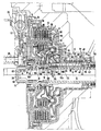
- a double clutch 6 consisting of two clutch units 2 and 4 is arranged in a housing, hereinafter referred to as bell housing 1, a double clutch 6 consisting of two clutch units 2 and 4 is arranged.
- the bell housing 1 can be arranged as a separate component in a drive train of an internal combustion engine between the engine and transmission or, alternatively, be integrally formed out of the gear housing.
- two transmission input shafts 8 and 10 are received, which cooperate in a known manner with the two coupling units 2 and 4 for the mutual switching of a first and second group of transmission gears.
- the double clutch 6 is sealed oil-tight by a separate housing cover 12 which is bolted to the bell housing 1 and sealed.
- the housing cover 12 at its radial outer end on a collar 16, in which a groove 14 is provided for receiving a sealing ring.
- a central opening 18 is provided, through which a drive hub 20 of a clutch basket 22 of the double clutch 6 is passed.
- the drive hub 20 has an external toothing 24, which engages in the internal toothing of a torsional vibration damper 26.
- the integrated in a dual mass flywheel torsional vibration damper is bolted to its primary side 27 on the crankshaft end 28 of the engine unit, not shown.
- the central opening 18 is bounded by an out of the housing cover 12 formed and inwardly directed bearing flange 30, on the outside of the clutch basket 22 is supported on the engine side via a radial bearing 32, the latter being formed in the present embodiment as a rolling bearing; Alternatively, a plain bearing design is possible.
- the clutch basket 22 is the transmission side extended by a rotary member 40 which surrounds the outer transmission input shaft coaxial and rotatable thereto.
- the rotary member 40 and the clutch basket 22 is supported at its gear-side end via a ball bearing 42 in the bell housing 1, wherein the ball bearing 42 is received in a cylindrically shaped neck portion 44 of the bell housing 1 and clamped in both axial directions.
- the ball bearing 42 is received on the gear side facing in a stepped bore of the neck portion 44 and is axially secured on the other side via a thrust washer 46.
- the thrust washer 46 is in turn secured by a snap ring 48 arranged in an internal groove of the cylindrical neck portion 44.
- a left-aligned and a right-aligned stop 48 and 50 are provided on the rotary member 40 to the left and right of the ball bearing 42.
- the flush-mounted stop 50 is in turn formed by a snap ring, which is inserted in a arranged on the outer circumference of the rotary member 40 circumferential groove.
- the bell housing 1 is closed at the end face of the cylindrical neck portion 44 by a second housing cover 52, which is screwed to the neck portion 44 and sealed by a 0 - ring 54 relative to the bell housing 1.
- the two through the housing cover 52 passed through gear shafts 8 and 10 are sealed by a shaft seal 56.
- the rotary member 40 has on its outer circumference three annular grooves 58, 60 and 62, over which, as explained in more detail later, the oil is supplied to the coupling units 2 and 4.
- the three annular grooves are sealed against each other by piston rings, which are inserted into correspondingly provided annular grooves 64, 66, 68 and 70.
- the oil supply is inserted between the rotary member 40 and the opening of the cylindrical neck portion 44, a bush 72 provided with oil supply openings 71.
- the outer transmission input shaft 10 is supported relative to the rotary member 40 of the clutch basket 22 by a trained as a needle bearing 74 radial bearing. Trained as a solid shaft inner transmission input shaft 8 is supported via a radial bearing 76 relative to the formed as a hollow shaft outer transmission input shaft 10.
- the radial bearing 76 is inserted in a formed in the solid shaft 8 annular groove;
- the shaft sealing ring 78 arranged at the front end of the hollow shaft 10 can be dimensioned smaller in its outer circumference.
- the shaft seal 78 serves to seal the guided between the hollow shaft 10 and the solid shaft 8 gear oil, the u. a. for lubrication of the radial bearing 76 is required.
- journal-shaped end 80 of the solid shaft 8 relative to the drive hub 20 may be supported by a trained as a needle bearing radial bearing 82.
- a shaft sealing ring 84 is provided between the inside of the bearing flange 30 and the outside of the drive hub 20.
- Both coupling units 2 and 4 have a plurality of disks designed as disks clutch disks, which are arranged one behind the other in alternation as driving externally toothed friction plates 86 and as driven internally toothed lamellae 88.
- the externally toothed friction plates, referred to below as outer plates 86, of the coupling unit 2 engage in grooves 90 of the coupling basket 22; Similarly, the externally toothed friction plates 86 engage the coupling unit 4 in grooves 92 of an integrally connected to the rotary member 40 of the clutch basket 22 outer disk carrier 94 a.
- the driven internal serrated lamellae, below referred to as inner plates 88, 96 and 98 are each assigned to an inner disc carrier.
- the inner disk carrier 96 of the coupling unit 2 is rotatably connected via a toothing 100 with the solid shaft 8, while the inner disk carrier 98 of the coupling unit 4 via a toothing 102 rotatably connected to the hollow shaft 10 is connected.
- actuating piston 104 and 106 are arranged, which press the outer plates 86 against the inner plates 88 via a corresponding Druckölbeetzschung.
- a pressure chamber 108 is formed, which is sealed by means of corresponding sealing elements 110 and 112.
- a pressure chamber 114 is provided for the actuating piston 106, which is also sealed by sealing elements 116 and 118.
- the pressure chamber 108 is supplied with oil via the annular groove 58 and an axial bore 124 provided in the rotary component 40, while the pressure chamber 114 is supplied with oil via the annular groove 62 and an axial bore 126.
- the two pressure chambers 108 and 114 are each a pressure compensation chamber 128 and 130 opposite, which are supplied via the annular groove 60 and via a third in the rotary member 40 arranged axial bore (not shown) with oil.
- centrifugal force due to the engagement movement of the two actuating pistons 104 and 106 are affected; by the pressure compensation chambers 128 and 130, a corresponding compensation of the force exerted on the piston centrifugal force forces is achieved.
- the pressure compensation chambers 128, 130 are in turn sealed by sealing elements 112 and 131, the sealing element 112 having two sealing lips 112a and 112b; Sealing lip 112a seals the pressure chamber 108, while sealing lip 112b seals the pressure compensation chamber 128.
- the pressure compensation chamber 130 is a through Wall portion 132 limited, in which an opening 134 is arranged. Via the opening 134, the oil in the pressure compensation chamber 130 for cooling the fins 86, 88 can pass into the coupling space.
- a sliding bearing 136 is provided between the clutch cover 36 and the inner disk carrier 96 for the axial support of both components; Similarly, between the inner disk carrier 96 of the coupling unit 2 and the inner disk carrier 98 of the coupling unit 4, a needle bearing 138 and between the inner disk carrier 98 and the wall portion 132, a sliding bearing 140 is provided.
Landscapes
- Engineering & Computer Science (AREA)
- General Engineering & Computer Science (AREA)
- Mechanical Engineering (AREA)
- Hydraulic Clutches, Magnetic Clutches, Fluid Clutches, And Fluid Joints (AREA)
- General Details Of Gearings (AREA)
- Mechanical Operated Clutches (AREA)
Abstract
Claims (10)
- Transmission à changement de vitesses pour un véhicule automobile comprenant un embrayage multiple à commande hydraulique, notamment un double embrayage, avec un premier arbre d'entrée de transmission (8) pour l'entraînement d'un premier groupe de rapports de transmission et un deuxième arbre d'entrée de transmission (10) pour l'entraînement d'un deuxième groupe de rapports de transmission, les deux arbres d'entrée de transmission (8, 10) étant associés à une unité d'embrayage respective (2, 4) et les deux arbres d'entrée de transmission (8, 10) et les deux unités d'embrayage (2, 4) étant disposés coaxialement les uns par rapport aux autres, et comprenant aussi un carter (1) stationnaire recevant les deux unités d'embrayage (2, 4), lequel peut être fermé du côté frontal par un couvercle de carter (12), et qui présente une ouverture centrale (18), à travers laquelle est guidé un moyeu d'entraînement d'une cloche d'embrayage (22), caractérisée en ce que le couvercle de carter (12) présente, autour de l'ouverture centrale (18), une bride de palier (30) sur le côté extérieur de laquelle est montée ou supportée la cloche d'embrayage (22).
- Transmission à changement de vitesses selon la revendication 1, caractérisée en ce que la cloche d'embrayage (22) est fermée par un couvercle d'embrayage (36) recevant le moyeu d'entraînement (20), qui est vissé sur la cloche d'embrayage (22).
- Transmission à changement de vitesses selon la revendication 2, caractérisée en ce que le couvercle d'embrayage (36) présente un rebord de palier (34) qui est supporté par le biais d'un premier palier radial (32) sur la bride de palier (30) du couvercle de carter (12).
- Transmission à changement de vitesses selon l'une quelconque des revendications précédentes, caractérisée en ce que la cloche d'embrayage (22) présente, dans son prolongement axial, un composant rotatif (40) pour l'alimentation en huile, qui est disposé coaxialement à l'arbre de transmission extérieur (10) et qui est supporté radialement et fixé axialement par le biais d'un palier fixe (42) dans le carter (1).
- Transmission à changement de vitesses selon la revendication 4, caractérisée en ce que le palier fixe présente un roulement à billes (42) qui est serré axialement dans le carter (1).
- Transmission à changement de vitesses selon la revendication 4 ou 5, caractérisée en ce que l'on prévoit sur la périphérie extérieure du composant rotatif (40) trois rainures annulaires périphériques (58, 60, 62) qui servent à l'alimentation en huile pour les actionnements des deux unités d'embrayage (2, 4) ainsi que pour l'alimentation en huile de refroidissement des unités d'embrayage (2, 4) pourvues de disques (86, 88).
- Transmission à changement de vitesses selon l'une quelconque des revendications précédentes, caractérisée en ce que l'arbre de transmission intérieur (8) présente une rainure annulaire dans laquelle est reçu un deuxième palier radial (76) pour assurer le support par rapport à l'arbre de transmission extérieur (10).
- Transmission à changement de vitesses selon l'une quelconque des revendications 4 à 7, caractérisée en ce que l'arbre de transmission extérieur (10) est supporté par le biais d'un troisième palier radial (74) dans le composant rotatif (40).
- Transmission à changement de vitesses selon la revendication 1, caractérisée en ce que l'on prévoit entre le côté intérieur de la bride de palier (30) et le côté extérieur du moyeu d'entraînement (20) de la cloche d'embrayage (22) une bague d'étanchéité d'arbre (84).
- Transmission à changement de vitesses selon la revendication 1, caractérisée en ce que le couvercle du carter (12) est vissé sur le carter (1) et est rendu étanche vis-à-vis de l'extérieur par le biais d'un joint torique (14).
Applications Claiming Priority (3)
| Application Number | Priority Date | Filing Date | Title |
|---|---|---|---|
| DE10223780 | 2002-05-29 | ||
| DE10223780A DE10223780C1 (de) | 2002-05-29 | 2002-05-29 | Gangschaltgetriebe für ein Kraftfahrzeug mit hydraulisch betätigbarer Mehrfachkupplung |
| PCT/EP2003/003108 WO2003102438A1 (fr) | 2002-05-29 | 2003-03-26 | Boite de vitesses pour automobile a embrayage a disques multiples a commande hydraulique |
Publications (3)
| Publication Number | Publication Date |
|---|---|
| EP1511947A1 EP1511947A1 (fr) | 2005-03-09 |
| EP1511947B1 true EP1511947B1 (fr) | 2010-03-03 |
| EP1511947B2 EP1511947B2 (fr) | 2017-03-15 |
Family
ID=28051329
Family Applications (1)
| Application Number | Title | Priority Date | Filing Date |
|---|---|---|---|
| EP03755924.2A Expired - Lifetime EP1511947B2 (fr) | 2002-05-29 | 2003-03-26 | Boite de vitesses pour automobile a embrayage a disques multiples a commande hydraulique |
Country Status (6)
| Country | Link |
|---|---|
| US (1) | US7147095B2 (fr) |
| EP (1) | EP1511947B2 (fr) |
| JP (1) | JP4473118B2 (fr) |
| KR (1) | KR100901608B1 (fr) |
| DE (2) | DE10223780C1 (fr) |
| WO (1) | WO2003102438A1 (fr) |
Families Citing this family (49)
| Publication number | Priority date | Publication date | Assignee | Title |
|---|---|---|---|---|
| DE10333431A1 (de) * | 2003-07-23 | 2005-02-10 | Zf Friedrichshafen Ag | Kupplungsanordnung in einem Automatgetriebe mit bauraumsparender Kühlmittelversorgung |
| EP1548313B2 (fr) * | 2003-12-23 | 2016-09-28 | Schaeffler Technologies AG & Co. KG | Dispositif de transmission de couple et train d'entraînement le comprenant |
| US20050189190A1 (en) * | 2004-02-27 | 2005-09-01 | Kowalsky Christopher J. | Electrohydraulic clutch assembly |
| DE102005063529B4 (de) * | 2004-06-21 | 2020-01-16 | Schaeffler Technologies AG & Co. KG | Nasslaufende Doppelkupplung in Lamellenbauweise |
| EP1609654B1 (fr) | 2004-06-21 | 2008-11-05 | LuK Lamellen und Kupplungsbau Beteiligungs KG | Dispositif de transfert de couple |
| DE102004043386B4 (de) * | 2004-09-08 | 2013-02-21 | Zf Friedrichshafen Ag | Getriebevorrichtung in Vorgelegebauweise |
| DE102004046297A1 (de) * | 2004-09-24 | 2006-03-30 | Zf Friedrichshafen Ag | Anordnung zur Abdichtung von koaxialen Antriebswellen |
| FR2875873B1 (fr) * | 2004-09-29 | 2006-12-15 | Renault Sas | Double embrayage humide pour moteur de vehicule automobile |
| EP1645765B1 (fr) * | 2004-10-06 | 2018-09-12 | BorgWarner, Inc. | Ensemble de transmission |
| DE102004055361B4 (de) * | 2004-11-05 | 2008-10-30 | Getrag Getriebe- Und Zahnradfabrik Hermann Hagenmeyer Gmbh & Cie Kg | Doppelkupplungsanordnung |
| DE102004058872B4 (de) * | 2004-12-06 | 2014-03-13 | Volkswagen Ag | Doppelkupplung |
| DE102004060595C5 (de) * | 2004-12-09 | 2013-12-19 | Getrag Getriebe- Und Zahnradfabrik Hermann Hagenmeyer Gmbh & Cie Kg | Doppelkupplungsanordnung |
| FR2879702A1 (fr) | 2004-12-17 | 2006-06-23 | Renault Sas | Systeme d'embrayage humide multiple a flasque d'entrainement integrant une cible emettrice de signaux representatifs de la vitesse de rotation dudit flasque |
| FR2880095B1 (fr) * | 2004-12-29 | 2008-07-04 | Renault Sas | Boite de vitesses dont l'huile de lubrification des pignons est isolee des embrayages |
| FR2880094B1 (fr) * | 2004-12-29 | 2008-07-04 | Renault Sas | Boite de vitesses a pignon d'attaque monte en porte a faux |
| FR2882121B1 (fr) | 2005-02-16 | 2007-06-15 | Renault Sas | Dispositif de gestion de fluide d'un reseau hydraulique d'une boite de vitesse automatique |
| JP4683956B2 (ja) * | 2005-02-24 | 2011-05-18 | 株式会社エクセディ | 複式クラッチ装置 |
| DE102005009187A1 (de) * | 2005-03-01 | 2006-09-14 | Zf Friedrichshafen Ag | Torsionsschwingungsdämpfer |
| DE102005025979A1 (de) † | 2005-06-03 | 2006-12-14 | Zf Friedrichshafen Ag | Doppelkupplungseinrichtung und Radiallagerungskonzept hierfür |
| WO2007051627A1 (fr) | 2005-11-04 | 2007-05-10 | Borgwarner Inc. | Amortisseur de vibrations de torsion avec un accouplement a un vilebrequin et combinaison d'un amortisseur de vibrations de torsion et d'un accouplement |
| DE102005059115A1 (de) * | 2005-12-10 | 2007-06-14 | Zf Friedrichshafen Ag | Ölschmiersystem für eine mit einem Gangschaltgetriebe wirkverbundene Mehrfachkupplung |
| FR2897409B1 (fr) | 2006-02-14 | 2009-02-06 | Renault Sas | Boite de vitesse compartimentee. |
| DE102006010113C5 (de) * | 2006-02-28 | 2010-05-20 | Getrag Getriebe- Und Zahnradfabrik Hermann Hagenmeyer Gmbh & Cie Kg | Doppelkupplungsanordnung für ein Doppelkupplungsgetriebe |
| DE102007009964A1 (de) * | 2006-03-22 | 2007-09-27 | Luk Lamellen Und Kupplungsbau Beteiligungs Kg | Hydraulische betätigte Doppelkupplung |
| DE102006014562A1 (de) * | 2006-03-29 | 2007-10-04 | Volkswagen Ag | Kupplungsvorrichtung mit einer Kupplung und einem damit verbundenen Drehschwingungsdämpfer sowie Getriebe mit einer solchen Kupplungsvorrichtung |
| DE102006027899B4 (de) * | 2006-06-17 | 2016-06-23 | Volkswagen Ag | Kupplungsanordnung in einem Getriebe eines Kraftfahrzeuges |
| KR20090055642A (ko) * | 2006-09-20 | 2009-06-02 | 지아이에프 게젤샤프트 퓌어 인더스트리포르슝 엠베하 | 주 구동축을 포함하는 구동트레인 및 특히 엔진 블록으로부터 형성되는 구동축을 포함하는 차량용 구동트레인 |
| DE102007013495A1 (de) | 2007-03-21 | 2008-09-25 | Zf Friedrichshafen Ag | Verfahren zur Steuerung einer automatisierten Reibungskupplung eines Doppelkupplungsgetriebes |
| DE102007019604A1 (de) * | 2007-04-24 | 2008-10-30 | Borgwarner Inc., Auburn Hills | Kupplungsanordnung |
| DE102008008062B4 (de) * | 2008-02-01 | 2014-05-22 | Getrag Getriebe- Und Zahnradfabrik Hermann Hagenmeyer Gmbh & Cie Kg | Doppelkupplungsanordnung |
| US9562572B2 (en) * | 2008-02-18 | 2017-02-07 | Borgwarner Inc. | Clutch device with a flex plate |
| DE102008060580B4 (de) * | 2008-06-03 | 2021-01-21 | Borgwarner Inc. | Mehrfach-Kupplungseinrichtung mit zwei Druckausgleichsräumen |
| DE102008055681B4 (de) | 2008-10-28 | 2020-10-15 | Magna Pt B.V. & Co. Kg | Doppelkupplungsanordnung für ein Doppelkupplungsgetriebe |
| DE102008055682C5 (de) | 2008-10-28 | 2017-11-02 | Getrag Getriebe- Und Zahnradfabrik Hermann Hagenmeyer Gmbh & Cie Kg | Doppelkupplung mit stehendem Kolben und verbesserten Einrücklagern |
| DE102010051447A1 (de) * | 2009-11-20 | 2011-05-26 | Schaeffler Technologies Gmbh & Co. Kg | Kupplungseinrichtung |
| DE102009056350A1 (de) | 2009-11-30 | 2011-06-01 | Schaeffler Technologies Gmbh & Co. Kg | Lageranordnung zur Abstützung einer Kupplungseinrichtung |
| DE102009055063B4 (de) | 2009-12-21 | 2023-03-23 | Zf Friedrichshafen Ag | Verfahren zum Betreiben einer Kupplung |
| DE102009055065A1 (de) | 2009-12-21 | 2011-06-22 | ZF Friedrichshafen AG, 88046 | Verfahren zur Adaption der Schnellbefüllzeit einer Kupplung |
| DE102014209618B4 (de) * | 2013-06-17 | 2022-12-22 | Schaeffler Technologies AG & Co. KG | Mehrfachkupplungseinrichtung |
| DE102014212805A1 (de) * | 2013-07-19 | 2015-01-22 | Schaeffler Technologies Gmbh & Co. Kg | Doppelkupplungseinrichtung |
| FR3024511B1 (fr) * | 2014-08-01 | 2018-01-12 | Valeo Embrayages | Dispositif d'embrayage pour un vehicule automobile |
| WO2016029912A1 (fr) | 2014-08-29 | 2016-03-03 | Schaeffler Technologies AG & Co. KG | Embrayage double |
| FR3026153B1 (fr) * | 2014-09-18 | 2018-02-23 | Valeo Embrayages | Module de transmission de couple destine a equiper une transmission d'un vehicule automobile |
| KR101786805B1 (ko) | 2016-04-18 | 2017-11-16 | 씨스톤 테크놀로지스(주) | 이중 클러치용 액츄에이터 |
| WO2017052024A1 (fr) | 2015-09-22 | 2017-03-30 | 씨스톤 테크놀로지스(주) | Embrayage double |
| DE102017206221B4 (de) | 2017-04-11 | 2022-12-22 | Zf Friedrichshafen Ag | Mehrfachkupplungsanordnung, Doppelkupplungsgetriebeanordnung sowie Kraftfahrzeug |
| DE102018203073A1 (de) * | 2018-03-01 | 2019-09-05 | Zf Friedrichshafen Ag | Antriebsanordnung für ein Schienenfahrzeug |
| FR3082253B1 (fr) * | 2018-06-07 | 2021-11-19 | Valeo Embrayages | Dispositif de transmission de couple |
| DE102021203150B3 (de) | 2021-03-29 | 2022-09-01 | Magna Pt B.V. & Co. Kg | Mehrfachkupplungsanordnung |
Family Cites Families (20)
| Publication number | Priority date | Publication date | Assignee | Title |
|---|---|---|---|---|
| DE37437C (de) | E. KNO-RECK, K. K. Postmeister in Stanislaus, Zablotowergasse 41, Galizien | Verfahren und Apparat zum Kopiren plastischer Gegenstände | ||
| US2375440A (en) * | 1940-12-30 | 1945-05-08 | Clifton R Roche | Automatic transmission |
| US3182775A (en) | 1962-08-30 | 1965-05-11 | Dana Corp | Hydrokinetic converter with multiple clutches and control means to simultaneously orselectively engage the same |
| US3747436A (en) * | 1971-06-28 | 1973-07-24 | Gen Electric | Power package |
| GB2108219B (en) * | 1981-10-28 | 1985-03-20 | Automotive Products Plc | Dual plate friction clutch |
| US4463621A (en) † | 1981-12-23 | 1984-08-07 | Ford Motor Company | Multiple countershaft automatic transmission |
| DE3446460A1 (de) † | 1984-12-20 | 1986-07-03 | Dr.Ing.H.C. F. Porsche Ag, 7000 Stuttgart | Doppelkupplung fuer ein kraftfahrzeuggetriebe |
| DE3615367A1 (de) † | 1986-05-06 | 1987-11-12 | Getrag Getriebe Zahnrad | Viergang-umlaufgetriebe |
| DE4302518B4 (de) * | 1992-01-30 | 2005-07-28 | Nissan Motor Co., Ltd., Yokohama | Kombination von mehreren Reibelementen für ein Automatikgetriebe |
| EP1111261B1 (fr) † | 1996-03-19 | 2002-11-13 | Exedy Corporation | Moyen limiteur de mouvement pour un embrayage à friction multidisques |
| US6021879A (en) † | 1999-04-05 | 2000-02-08 | General Motors Corporation | Rotating clutch balance apparatus |
| DE10004179C5 (de) * | 1999-09-30 | 2017-06-29 | Volkswagen Ag | Mehrfach-Kupplungseinrichtung |
| DE10004190B4 (de) * | 1999-09-30 | 2013-02-07 | Volkswagen Ag | Mehrfach-Kupplungseinrichtung |
| CN1401059A (zh) * | 2000-02-15 | 2003-03-05 | 卢克摩擦片和离合器两合公司 | 扭矩传递装置 |
| EP1174631B1 (fr) † | 2000-07-17 | 2007-01-24 | ZF Sachs AG | Dispositif d'accouplement multiple |
| DE10044493B4 (de) * | 2000-09-08 | 2012-05-03 | Zf Sachs Ag | Mehrfach-Kupplungseinrichtung, insbesondere Doppel-Kupplungseinrichtung, für lastschaltbare Getriebe |
| EP1226992B1 (fr) † | 2001-01-25 | 2004-07-21 | ZF Sachs AG | Dispositif d'accouplement multiple adapté à être monté comme unité de montage préassemblée |
| DE10114281B4 (de) † | 2001-03-23 | 2008-12-11 | Zf Sachs Ag | Mehrfach-Kupplungseinrichtung und Radiallagerungskonzept hierfür |
| EP1412650A1 (fr) † | 2001-07-31 | 2004-04-28 | ZF Sachs AG | Ensemble embrayage multiple |
| DE10203618A1 (de) * | 2001-07-31 | 2003-02-13 | Zf Sachs Ag | Mehrfach-Kupplungseinrichtung |
-
2002
- 2002-05-29 DE DE10223780A patent/DE10223780C1/de not_active Expired - Fee Related
-
2003
- 2003-03-26 DE DE50312478T patent/DE50312478D1/de not_active Expired - Lifetime
- 2003-03-26 KR KR1020047019122A patent/KR100901608B1/ko not_active Expired - Fee Related
- 2003-03-26 JP JP2004509291A patent/JP4473118B2/ja not_active Expired - Fee Related
- 2003-03-26 EP EP03755924.2A patent/EP1511947B2/fr not_active Expired - Lifetime
- 2003-03-26 US US10/507,632 patent/US7147095B2/en not_active Expired - Lifetime
- 2003-03-26 WO PCT/EP2003/003108 patent/WO2003102438A1/fr not_active Ceased
Also Published As
| Publication number | Publication date |
|---|---|
| JP4473118B2 (ja) | 2010-06-02 |
| EP1511947B2 (fr) | 2017-03-15 |
| US7147095B2 (en) | 2006-12-12 |
| US20050139023A1 (en) | 2005-06-30 |
| KR100901608B1 (ko) | 2009-06-08 |
| WO2003102438A1 (fr) | 2003-12-11 |
| KR20050005496A (ko) | 2005-01-13 |
| DE50312478D1 (de) | 2010-04-15 |
| JP2005527758A (ja) | 2005-09-15 |
| EP1511947A1 (fr) | 2005-03-09 |
| DE10223780C1 (de) | 2003-10-16 |
Similar Documents
| Publication | Publication Date | Title |
|---|---|---|
| EP1511947B1 (fr) | Boite de vitesses pour automobile a embrayage a disques multiples a commande hydraulique | |
| EP1813832B2 (fr) | Système d'embrayage comprenant un dispositif d'embrayage multiple à commande hydraulique | |
| DE112010004839B4 (de) | Drehmomentübertragungseinrichtung | |
| EP2504596B2 (fr) | Dispositif d'embrayage multiple, composant, ensembles et procédé de montage | |
| DE102007039856B4 (de) | Kraftübertragungseinrichtung | |
| EP1522753A1 (fr) | Embrayage double hydraulique | |
| DE10034677A1 (de) | Mehrfachkupplungsanordnung | |
| WO2010081451A1 (fr) | Ensemble embrayage | |
| DE102012201524A1 (de) | Drehmomentübertragungseinrichtung | |
| DE102009047953B4 (de) | Doppelkupplung für ein Doppelkupplungsgetriebe | |
| DE102013216333A1 (de) | Mehrfachkupplungsvorrichtung, insbesondere Doppelkupplungsvorrichtung | |
| EP1585907A2 (fr) | Systeme d'embrayage multiple a deux configurations d'embrayage accouplables pour entrer en rotation commune | |
| DE102005003508A1 (de) | Mehrfach-Kupplungseinrichtung | |
| DE10358902B4 (de) | Torsionsschwingungsdämpfer | |
| DE19820503B4 (de) | Torsionsschwingungsdämpfer mit zumindest einer Lagerung zwischen Dämpferelementen | |
| EP3759371A1 (fr) | Système d'embrayage et unité d'entraînement présentant ce système d'embrayage | |
| DE10004952C2 (de) | Überbrückungsvorrichtung für einen Drehmomentwandler | |
| EP1602846B1 (fr) | Dispositif d'embrayage | |
| DE102005044227A1 (de) | Lamellen-Kupplungseinrichtung | |
| EP3826873B1 (fr) | Module hybride doté d'un arbre d'entrée à passage tournant et dispositif d'actionnement pour un embrayage parmi plusieurs embrayages et chaîne cinématique | |
| DE19845695B4 (de) | Torsionsschwingungsdämpfer mit wenigstens einer Schutzeinrichtung gegen durch Mikrobewegungen bedingte Schäden | |
| EP2089636A1 (fr) | Embrayage à friction pour la chaîne cinématique d'un véhicule | |
| DE102009020950B4 (de) | Doppelkupplung mit einem Betätigungskolben und einer Verdrehsicherung für den Betätigungskolben | |
| DE102022113512B3 (de) | Hybridmodul | |
| EP3696436B1 (fr) | Dispositif d'embrayage pour une machine de travail agricole |
Legal Events
| Date | Code | Title | Description |
|---|---|---|---|
| PUAI | Public reference made under article 153(3) epc to a published international application that has entered the european phase |
Free format text: ORIGINAL CODE: 0009012 |
|
| 17P | Request for examination filed |
Effective date: 20041229 |
|
| AK | Designated contracting states |
Kind code of ref document: A1 Designated state(s): AT BE BG CH CY CZ DE DK EE ES FI FR GB GR HU IE IT LI LU MC NL PT RO SE SI SK TR |
|
| AX | Request for extension of the european patent |
Extension state: AL LT LV MK |
|
| DAX | Request for extension of the european patent (deleted) | ||
| RBV | Designated contracting states (corrected) |
Designated state(s): DE FR GB IT |
|
| RAP1 | Party data changed (applicant data changed or rights of an application transferred) |
Owner name: DR. ING. H.C. F. PORSCHE AKTIENGESELLSCHAFT Owner name: ZF SACHS AG |
|
| RAP1 | Party data changed (applicant data changed or rights of an application transferred) |
Owner name: DR. ING. H.C. F. PORSCHE AKTIENGESELLSCHAFT Owner name: ZF SACHS AG |
|
| GRAP | Despatch of communication of intention to grant a patent |
Free format text: ORIGINAL CODE: EPIDOSNIGR1 |
|
| GRAS | Grant fee paid |
Free format text: ORIGINAL CODE: EPIDOSNIGR3 |
|
| GRAA | (expected) grant |
Free format text: ORIGINAL CODE: 0009210 |
|
| AK | Designated contracting states |
Kind code of ref document: B1 Designated state(s): DE FR GB IT |
|
| REG | Reference to a national code |
Ref country code: GB Ref legal event code: FG4D Free format text: NOT ENGLISH |
|
| REF | Corresponds to: |
Ref document number: 50312478 Country of ref document: DE Date of ref document: 20100415 Kind code of ref document: P |
|
| PLBI | Opposition filed |
Free format text: ORIGINAL CODE: 0009260 |
|
| PLAX | Notice of opposition and request to file observation + time limit sent |
Free format text: ORIGINAL CODE: EPIDOSNOBS2 |
|
| 26 | Opposition filed |
Opponent name: SCHAEFFLER TECHNOLOGIES GMBH & CO. KG Effective date: 20101203 |
|
| REG | Reference to a national code |
Ref country code: GB Ref legal event code: 732E Free format text: REGISTERED BETWEEN 20110310 AND 20110316 |
|
| PLBB | Reply of patent proprietor to notice(s) of opposition received |
Free format text: ORIGINAL CODE: EPIDOSNOBS3 |
|
| REG | Reference to a national code |
Ref country code: GB Ref legal event code: 732E Free format text: REGISTERED BETWEEN 20110331 AND 20110406 |
|
| REG | Reference to a national code |
Ref country code: FR Ref legal event code: TQ |
|
| PLAB | Opposition data, opponent's data or that of the opponent's representative modified |
Free format text: ORIGINAL CODE: 0009299OPPO |
|
| R26 | Opposition filed (corrected) |
Opponent name: SCHAEFFLER TECHNOLOGIES AG & CO. KG Effective date: 20101203 |
|
| APBM | Appeal reference recorded |
Free format text: ORIGINAL CODE: EPIDOSNREFNO |
|
| APBP | Date of receipt of notice of appeal recorded |
Free format text: ORIGINAL CODE: EPIDOSNNOA2O |
|
| APAH | Appeal reference modified |
Free format text: ORIGINAL CODE: EPIDOSCREFNO |
|
| APBQ | Date of receipt of statement of grounds of appeal recorded |
Free format text: ORIGINAL CODE: EPIDOSNNOA3O |
|
| REG | Reference to a national code |
Ref country code: DE Ref legal event code: R081 Ref document number: 50312478 Country of ref document: DE Owner name: DR. ING. H.C. F. PORSCHE AKTIENGESELLSCHAFT, DE Free format text: FORMER OWNER: DR. ING. H.C. F. PORSCHE AKTIEN, ZF SACHS AG, , DE Effective date: 20130326 Ref country code: DE Ref legal event code: R081 Ref document number: 50312478 Country of ref document: DE Owner name: ZF FRIEDRICHSHAFEN AG, DE Free format text: FORMER OWNER: DR. ING. H.C. F. PORSCHE AKTIEN, ZF SACHS AG, , DE Effective date: 20130326 Ref country code: DE Ref legal event code: R081 Ref document number: 50312478 Country of ref document: DE Owner name: ZF FRIEDRICHSHAFEN AG, DE Free format text: FORMER OWNERS: DR. ING. H.C. F. PORSCHE AKTIENGESELLSCHAFT, 70435 STUTTGART, DE; ZF SACHS AG, 97424 SCHWEINFURT, DE Effective date: 20130326 Ref country code: DE Ref legal event code: R081 Ref document number: 50312478 Country of ref document: DE Owner name: DR. ING. H.C. F. PORSCHE AKTIENGESELLSCHAFT, DE Free format text: FORMER OWNERS: DR. ING. H.C. F. PORSCHE AKTIENGESELLSCHAFT, 70435 STUTTGART, DE; ZF SACHS AG, 97424 SCHWEINFURT, DE Effective date: 20130326 |
|
| PLAB | Opposition data, opponent's data or that of the opponent's representative modified |
Free format text: ORIGINAL CODE: 0009299OPPO |
|
| APBU | Appeal procedure closed |
Free format text: ORIGINAL CODE: EPIDOSNNOA9O |
|
| R26 | Opposition filed (corrected) |
Opponent name: SCHAEFFLER TECHNOLOGIES GMBH & CO. KG Effective date: 20101203 |
|
| REG | Reference to a national code |
Ref country code: FR Ref legal event code: TQ Owner name: ZF FRIEDRICHSHAFEN AG, DE Effective date: 20150210 Ref country code: FR Ref legal event code: TQ Owner name: DR.ING. H.C.F.PORCHE AG, DE Effective date: 20150210 |
|
| REG | Reference to a national code |
Ref country code: GB Ref legal event code: 732E Free format text: REGISTERED BETWEEN 20150319 AND 20150325 |
|
| REG | Reference to a national code |
Ref country code: FR Ref legal event code: PLFP Year of fee payment: 14 |
|
| REG | Reference to a national code |
Ref country code: DE Ref legal event code: R081 Ref document number: 50312478 Country of ref document: DE Owner name: DR. ING. H.C. F. PORSCHE AKTIENGESELLSCHAFT, DE Free format text: FORMER OWNERS: DR. ING. H.C. F. PORSCHE AKTIENGESELLSCHAFT, 70435 STUTTGART, DE; ZF FRIEDRICHSHAFEN AG, 88046 FRIEDRICHSHAFEN, DE |
|
| PGFP | Annual fee paid to national office [announced via postgrant information from national office to epo] |
Ref country code: GB Payment date: 20160321 Year of fee payment: 14 Ref country code: FR Payment date: 20160321 Year of fee payment: 14 |
|
| PGFP | Annual fee paid to national office [announced via postgrant information from national office to epo] |
Ref country code: IT Payment date: 20160324 Year of fee payment: 14 |
|
| PUAH | Patent maintained in amended form |
Free format text: ORIGINAL CODE: 0009272 |
|
| STAA | Information on the status of an ep patent application or granted ep patent |
Free format text: STATUS: PATENT MAINTAINED AS AMENDED |
|
| 27A | Patent maintained in amended form |
Effective date: 20170315 |
|
| AK | Designated contracting states |
Kind code of ref document: B2 Designated state(s): DE FR GB IT |
|
| REG | Reference to a national code |
Ref country code: DE Ref legal event code: R102 Ref document number: 50312478 Country of ref document: DE |
|
| GBPC | Gb: european patent ceased through non-payment of renewal fee |
Effective date: 20170326 |
|
| REG | Reference to a national code |
Ref country code: FR Ref legal event code: ST Effective date: 20171130 |
|
| PG25 | Lapsed in a contracting state [announced via postgrant information from national office to epo] |
Ref country code: FR Free format text: LAPSE BECAUSE OF NON-PAYMENT OF DUE FEES Effective date: 20170331 |
|
| PG25 | Lapsed in a contracting state [announced via postgrant information from national office to epo] |
Ref country code: GB Free format text: LAPSE BECAUSE OF NON-PAYMENT OF DUE FEES Effective date: 20170326 Ref country code: IT Free format text: LAPSE BECAUSE OF NON-PAYMENT OF DUE FEES Effective date: 20170326 |
|
| PGFP | Annual fee paid to national office [announced via postgrant information from national office to epo] |
Ref country code: DE Payment date: 20200227 Year of fee payment: 18 |
|
| REG | Reference to a national code |
Ref country code: DE Ref legal event code: R119 Ref document number: 50312478 Country of ref document: DE |
|
| PG25 | Lapsed in a contracting state [announced via postgrant information from national office to epo] |
Ref country code: DE Free format text: LAPSE BECAUSE OF NON-PAYMENT OF DUE FEES Effective date: 20211001 |