EP1511940B1 - Dispositif de commande - Google Patents
Dispositif de commande Download PDFInfo
- Publication number
- EP1511940B1 EP1511940B1 EP03810425A EP03810425A EP1511940B1 EP 1511940 B1 EP1511940 B1 EP 1511940B1 EP 03810425 A EP03810425 A EP 03810425A EP 03810425 A EP03810425 A EP 03810425A EP 1511940 B1 EP1511940 B1 EP 1511940B1
- Authority
- EP
- European Patent Office
- Prior art keywords
- face
- control device
- valve piston
- bore
- controlling
- Prior art date
- Legal status (The legal status is an assumption and is not a legal conclusion. Google has not performed a legal analysis and makes no representation as to the accuracy of the status listed.)
- Expired - Lifetime
Links
- 239000012530 fluid Substances 0.000 claims description 38
- 238000007789 sealing Methods 0.000 claims description 6
- 230000001276 controlling effect Effects 0.000 description 9
- 238000010276 construction Methods 0.000 description 6
- 238000007654 immersion Methods 0.000 description 3
- 230000000694 effects Effects 0.000 description 2
- 230000007935 neutral effect Effects 0.000 description 2
- 238000000926 separation method Methods 0.000 description 2
- 230000003750 conditioning effect Effects 0.000 description 1
- 230000000875 corresponding effect Effects 0.000 description 1
- 238000011161 development Methods 0.000 description 1
- 230000018109 developmental process Effects 0.000 description 1
- 238000009434 installation Methods 0.000 description 1
- 238000004519 manufacturing process Methods 0.000 description 1
Images


Classifications
-
- F—MECHANICAL ENGINEERING; LIGHTING; HEATING; WEAPONS; BLASTING
- F15—FLUID-PRESSURE ACTUATORS; HYDRAULICS OR PNEUMATICS IN GENERAL
- F15B—SYSTEMS ACTING BY MEANS OF FLUIDS IN GENERAL; FLUID-PRESSURE ACTUATORS, e.g. SERVOMOTORS; DETAILS OF FLUID-PRESSURE SYSTEMS, NOT OTHERWISE PROVIDED FOR
- F15B11/00—Servomotor systems without provision for follow-up action; Circuits therefor
- F15B11/006—Hydraulic "Wheatstone bridge" circuits, i.e. with four nodes, P-A-T-B, and on-off or proportional valves in each link
Definitions
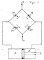
- a hydraulic control device for controlling two pressure chambers A and B of a hydraulic motor in the form of a working cylinder according to the principle of a hydraulic bridge circuit operates.
- a fluid pump P conveys fluid via throttle points D1, D2, D3 and D4 to a tank T.
- the throttle points form for the fluid passages whose Naturalströmqueritese are variable.
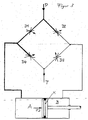
- the throttle points D1, D2, D3 and D4 work in pairs, namely D1 with D3 and D2 with D4. If, for example, the flow cross-section of D1 and D3 is reduced, the flow resistance of the fluid increases, which is manifested by an increased fluid pressure with a constant fluid flow conveyed by the fluid pump P. This situation is shown in FIG. 2. There, the increased fluid pressure is represented by the increased line thickness of the lines. Via a connecting line 1, the increased fluid pressure is communicated to the pressure chamber B of the working cylinder. On a piston K of a working cylinder creates a pressure force F1, which moves the piston K to the left.
- slider-sleeve system called a slider part with a circular cross-section in a designated sleeve part with a circular, inner tube cross-section axially or tangentially back and forth from a defined neutral position.
- throttling points D1, D2, D3 and D4 of a hydraulic bridge circuit arise.
- Such a control device can be composed of four modules M1, M2, M3 and M4, each of which assumes the function of the throttle points D1, D2, D3 and D4 of a hydraulic bridge circuit.
- the four modules can be designed identical.
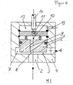
- One of these modules is shown in principle in FIG. It has a housing bore in a housing 4, in which a valve piston 5 is arranged axially displaceable
- a piston seal S divides the housing bore into subspaces in which different pressures can prevail.
- a small fluid stream flows through a bore 9 in a space 10 and through a bore 11 in one. Room 12 and from there via an opening 13 in the tank T ( Figure 1) back.
- the prior art correspond to control devices in which each of the throttle points D1, D2, D3 and D4 of a hydraulic bridge circuit is replaced by one of the identical modules M1, M2, M3 and M4.
- a controller of modular construction is e.g. from DE 100 06 141 A1 Industrial.DDort to controlled throttling of the flow rate of the hydraulic pressure medium, a two-sided, symmetrical structure is proposed, in each of which an actively controlled valve (see “48” in the figure there) in operative connection with a passive valve ("49") stands.
- the construction is very compact and has u.a. the advantage that the manufacturing and assembly costs are significantly reduced.
- the structure is not completely symmetrical because the active valves are more complex than the passive valves. This is necessary because each active valve must simultaneously control its associated passive valve.
- a control device known as a servo valve which has two identical modules. These are referred to there as “part valves” or “cartridges 4 and 5" (see description there column 1, lines 50 ff. And Figure 3).
- Each of the Cartridges comprise two throttles 1 and 2a or 1a and 2, which are part of a hydraulic bridge circuit ( Figures 1 and 2).
- the design has, among other things: the advantage that both cartridges with an open center and cartridges with a closed center can be used (see column 2, lines 65 ff.).
- the throttling points controlled in the same direction in each case, such as the throttles 1 and 1a (see FIGS. 1 and 2), are spatially separated from one another in each case in one of the part valves (cartridge 4 or 5 in FIG. 3).
- the design requires a precise symmetrical valve control on both sides, so that the bridge circuit can work optimally.
- the invention simplifies the construction of a control device which has at least two throttle points controllable in the same direction by combining the functionally interacting throttle points, ie D1 with D3 and / or D2 with D4, to form a spatial and functional unit.
- a control device which has at least two throttle points controllable in the same direction by combining the functionally interacting throttle points, ie D1 with D3 and / or D2 with D4, to form a spatial and functional unit.
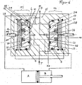
- FIG. 6 shows a control device of the construction according to the invention.
- the modules M1 and M3 of the preceding figures are to the module M5 and the modules M2 and M4 are combined to form the module M6.
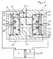
- the throttle points D1, D2, D3 and D4 of a hydraulic bridge circuit shown in FIG. 6 result as circular disc ring gaps of small and variable height between a housing 15 and controlling end faces S1 and S2 of plunger 16 and 17.
- the continuous hydraulic separation between the throttle points D1 and D3 or D4 and D2 is effected in each case by an elastic sealing element 18 or 19, which is embedded concentrically between the respective two disc-ring gaps of a controlling end face.
- lines shown as dashes eg: L
- FIG. 7 shows another switching situation of the control device according to FIG. 6.
- Increased line weights indicate areas of the lines with increased fluid pressure.
- a throttle needle 24 is moved by a force in the mouth of a throttle bore 25.
- the low fluid flow flowing through a bore 26 to the throttle bore 25 is brought to a higher fluid pressure by the reduced flow cross-section between throttle needle 24 and mouth of the throttle bore 25.
- a left throttling needle 24a is pushed into the mouth of a throttle bore 25a in FIG. 6, the small fluid flow flowing through a bore 28 to the throttle bore 25a is brought to a higher fluid pressure by reducing the flow cross-section between throttling needle 24a and mouth of the throttle bore 25a.
- the system pressure With increasing immersion depth of the Drosea needle 24a in the mouth of the throttle bore 25a, the system pressure, so the fluid pressure in an annular space 40 and in the space 30 increases. This pressure is transmitted via the throttle point D2 and the annular groove 22 to the pressure chamber B.
- the bores 26, 28 serve the so-called pilot control, which is known per se.
- the two valve pistons 16 and 17 with their controlling end faces S1, S2 pressed without the effect of the valve pilot control described above against the facing end surfaces of the housing bores become.
- the actuating force required for this purpose can then be applied mechanically, electrically or pneumatically.
- the non-activated, thus not controlled, valve piston 16 with its left, rear end face opposes one Contact surface 27 pressed.
- the mouth of the bore 28 is closed here.
- valve piston 16 is activated in the other actuation case, then the corresponding action takes place with the then non-activated valve piston 17, which is pressed by the system pressure to the right against its front-side abutment surface 39, that the mouth of the bore 26 is closed here with the effect described above.
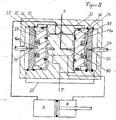
- valve pistons 16a and 17a are each provided with an annular collar (annular rib) 35 and 34, which in the exemplary case of the installation of the valve piston 16a on the contact surface 27 results in a clear hydraulic separation between the chambers 36 and 37 and thus in the in Figure 8 illustrated switching situation the fluid inlet from the space 36 via the space 37 to the throttle bore 31 closes.
- annular collar annular rib
- Control device which can be used in a hydraulic bridge circuit, wherein the four throttle points are designed as four seat valve modules and the two cooperating in the bridge circuit and diagonally opposite modules are spatially combined.
- a controlling end face S1, S2 of two drum-shaped and axially movable in two housing bores Valve piston 16, 17 two concentric annular grooves 20, 21 and 22, 23 with a concentrically arranged therebetween sealing element 18, 19 is inserted, whereby in each case between this valve piston side end face S1 and S2 and facing her housing bore side face two annular throttle gaps low and variable height which act as the said spatially combined modules.
- valve piston The movement of the valve piston can take place via a so-called valve precontrol principle or by applying forces from the outside.
- the two concentric annular grooves can also be embedded in each case in the housing bore-side end face.
- the pilot control fluid is supplied through a bore 28 or 26 in the valve piston 16 or 17 or via a separate line 32 and 33, the mouths on the rear end face of the valve piston so are arranged so that they are closed by conditioning the valve piston to a respective movement limiting contact surface 27 to avoid unnecessary leakage fluid flows when the currently not activated valve piston is pressed by increased fluid pressure against this contact surface.
Landscapes
- Engineering & Computer Science (AREA)
- Physics & Mathematics (AREA)
- Fluid Mechanics (AREA)
- Mechanical Engineering (AREA)
- General Engineering & Computer Science (AREA)
- Fluid-Pressure Circuits (AREA)
Claims (10)
- Dispositif de commande comprenant à chaque fois deux points d'étranglement hydrauliques (D1, D3) et (D2, D4) commandables dans le même sens et simultanément, et deux pistons de soupape (16, 17) dans un alésage de carter respectif, ayant les caractéristiques suivantes :- les pistons de soupape (16, 17) sont disposés de manière à pouvoir coulisser dans la direction axiale de l'alésage de carter et séparent à chaque fois un premier espace d'un deuxième espace,- la première des deux surfaces frontales de chaque piston de soupape (16, 17) est réalisée sous la forme d'une surface frontale de commande (S1, S2),- la première surface frontale (S1, S2) ou la surface frontale de l'alésage de carter (B1, B2) tournée vers elle présente un élément d'étanchéité de forme annulaire (18, 19) qui sépare une surface partielle interne de la première surface frontale (S1, S2) d'une surface partielle externe,- la surface partielle externe comprend le premier des points d'étranglement (D1, D4), qui est connecté au premier espace,- la surface partielle interne comprend le deuxième point d'étranglement (D2, D3) et- le dispositif de commande est un montage en pont hydrauliquecaractérisé par les caractéristiques suivantes :- dans le piston de soupape (16, 17) est pratiqué un alésage (26, 28), l'alésage relie l'espace pour le fluide affluant prévu entre la surface frontale de commande (S1, S2) du piston de soupape (16, 17) et le carter (15) à la surface frontale arrière du piston de soupape (16, 17) sans effet de commande,- l'embouchure de cette alésage (26, 28) prévue ici est alors fermée lorsque le piston de soupape (16, 17) est pressé avec sa surface frontale sans effet de commande contre une surface d'appui (27, 39) prévue à cet endroit.
- Dispositif de commande selon la revendication 1, caractérisé en ce que dans la surface frontale de commande (S1, S2) du piston de soupape (16, 17) ou dans la surface frontale (B1, B2) tournée vers elle de l'alésage de carter, sont pratiqués deux évidements (20, 21 et 22, 23) pour la sollicitation en pression par un fluide, entre lesquels se trouve l'élément d'étanchéité (18, 19) et en ce qu'entre la surface frontale de commande (S1, S2) et la surface d'appui du côté du carter (B1, B2), se trouvent des fentes en forme annulaire circulaire de faible hauteur variable, qui servent de points d'étranglement hydrauliques (D1, D3, D2, D4).
- Dispositif de commande selon la revendication 1 ou 2, caractérisé en ce que les évidements (20, 21 et 22, 23) sont des rainures concentriques de forme annulaire.
- Dispositif de commande selon l'une quelconque des revendications précédentes, caractérisé en ce que les deux points d'étranglement (D1 et D3, ou D2 et D4) coopérant dans le même sens et diagonalement opposés l'un à l'autre dans le montage en pont hydraulique se trouvent à chaque fois entre un piston de soupape commun (16, 17) et la surface frontale (B1, B2) tournée vers lui de l'alésage de carter.
- Dispositif de commande selon l'une quelconque des revendications précédentes, caractérisé en ce que le piston de soupape (16, 17) peut être sollicité sur sa surface frontale opposée à la surface frontale de commande (S1, S2) à la manière d'une commande dite préalable avec une partie de la pression de fluide d'une pompe à fluide (P), en ce que le piston de soupape (16, 17) est pressé avec sa surface frontale de commande (S1, S2) contre la surface frontale (B1, B2) de l'alésage de carter tournée vers elle.
- Dispositif de commande selon l'une quelconque des revendications 1 à 4, caractérisé en ce que le piston de soupape (16, 17) est pressé par une force mécanique, électrique, hydraulique ou pneumatique pouvant être appliquée de l'extérieur avec sa surface frontale de commande (S1, S2) contre la surface frontale (B1, B2) tournée vers elle de l'alésage de carter.
- Dispositif de commande selon l'une quelconque des revendications 1 à 5, caractérisé en ce que l'espace (36, 38) entre une partie de la surface frontale sans effet de commande du piston de soupape (16, 17) et une surface d'appui (27, 39) tournée vers elle est connecté à la pompe à fluide (P) et ladite partie s'applique de manière hermétique par un épaulement rehaussé (34, 35) sur la surface frontale sans effet de commande ou sur la surface d'appui (27, 39) et sépare deux espaces dont celui qui n'est pas connecté directement à la pompe est connecté à la commande préalable hydraulique.
- Dispositif de commande selon la revendication 7, caractérisé en ce que l'épaulement (34, 35) est disposé de manière essentiellement concentrique à l'axe longitudinal du piston de soupape (16, 17).
- Dispositif de commande selon l'une quelconque des revendications 1 à 8, caractérisé en ce que lesdits deux pistons de soupape (16, 17) sont réunis dans un carter commun (15).
- Dispositif de commande selon l'une quelconque des revendications 1 à 8, caractérisé en ce que lesdits deux pistons de soupape (16, 17) sont à chaque fois montés séparément dans un carter respectif.
Applications Claiming Priority (3)
| Application Number | Priority Date | Filing Date | Title |
|---|---|---|---|
| DE10251127 | 2002-11-02 | ||
| DE2002151127 DE10251127B4 (de) | 2002-11-02 | 2002-11-02 | Steuereinrichtung |
| PCT/EP2003/012144 WO2004042234A1 (fr) | 2002-11-02 | 2003-10-31 | Dispositif de commande |
Publications (2)
| Publication Number | Publication Date |
|---|---|
| EP1511940A1 EP1511940A1 (fr) | 2005-03-09 |
| EP1511940B1 true EP1511940B1 (fr) | 2006-05-24 |
Family
ID=32115150
Family Applications (1)
| Application Number | Title | Priority Date | Filing Date |
|---|---|---|---|
| EP03810425A Expired - Lifetime EP1511940B1 (fr) | 2002-11-02 | 2003-10-31 | Dispositif de commande |
Country Status (3)
| Country | Link |
|---|---|
| EP (1) | EP1511940B1 (fr) |
| DE (1) | DE10251127B4 (fr) |
| WO (1) | WO2004042234A1 (fr) |
Families Citing this family (1)
| Publication number | Priority date | Publication date | Assignee | Title |
|---|---|---|---|---|
| US9328747B2 (en) * | 2013-03-15 | 2016-05-03 | Mts Systems Corporation | Servo actuator load vector generating system |
Family Cites Families (4)
| Publication number | Priority date | Publication date | Assignee | Title |
|---|---|---|---|---|
| DE4224606A1 (de) * | 1992-07-25 | 1994-01-27 | Joerg J Prof Dipl Ing Linser | Servoventil |
| DE4238331A1 (de) * | 1992-11-13 | 1994-05-19 | Linser Joerg Prof Dipl Ing Fh | Servoventil |
| DE19601662A1 (de) * | 1996-01-18 | 1997-07-24 | Joerg J Prof Dipl Ing Linser | Servoventil in Kartuschenausführung, vorzugsweise für Hilfskraftlenkungen |
| DE10006141A1 (de) * | 2000-02-11 | 2001-09-06 | Zf Lenksysteme Gmbh | Elektrohydraulische Steuervorrichtung |
-
2002
- 2002-11-02 DE DE2002151127 patent/DE10251127B4/de not_active Expired - Fee Related
-
2003
- 2003-10-31 WO PCT/EP2003/012144 patent/WO2004042234A1/fr not_active Ceased
- 2003-10-31 EP EP03810425A patent/EP1511940B1/fr not_active Expired - Lifetime
Also Published As
| Publication number | Publication date |
|---|---|
| DE10251127B4 (de) | 2008-11-06 |
| DE10251127A1 (de) | 2004-05-19 |
| EP1511940A1 (fr) | 2005-03-09 |
| WO2004042234A1 (fr) | 2004-05-21 |
Similar Documents
| Publication | Publication Date | Title |
|---|---|---|
| DE2543466C3 (de) | Fluidgesteuertes Ventil | |
| US3294120A (en) | Multiway control valves | |
| DE3114437C2 (de) | Druckregelventil | |
| DE112007001455T5 (de) | Strömungsmittelgesteuertes Ventil | |
| DE3835705A1 (de) | Stossdaempfer zur daempfung von bewegungsablaeufen | |
| DD152170A5 (de) | Sicherheitsventil | |
| DE3817120A1 (de) | Sicherheitsventil | |
| EP0921322B1 (fr) | Soupape de réglage pneumatique | |
| EP3230618B1 (fr) | Dispositif formant vanne d'amortissement réglable | |
| WO2023166073A1 (fr) | Vanne | |
| DE102021213469B3 (de) | Sicherheitsventileinrichtung | |
| EP3087279A1 (fr) | Ensemble de soupapes | |
| EP1511940B1 (fr) | Dispositif de commande | |
| WO2009010077A1 (fr) | Distributeur pour applications redondantes | |
| WO2011000515A1 (fr) | Ensemble à soupape | |
| EP1254316B1 (fr) | Dispositif de commande pour servomoteur hydraulique | |
| DE102005021850B3 (de) | Fluidsteuerventil | |
| EP1042615B1 (fr) | Dispositif de travail actionne par un fluide | |
| EP1415095B1 (fr) | Dispositif de commande destinee au mouvement continu d'un moteur d'un servomoteur hydraulique | |
| DE3817122A1 (de) | Sicherheitsventil | |
| DE4129755A1 (de) | Doppelsitz-ventilanordnung | |
| DE112022002024T5 (de) | Druckausgleichsventil | |
| DE112016004713T5 (de) | Ventilvorrichtung | |
| EP0376023B1 (fr) | Soupape électrohydraulique proportionnelle | |
| DE102005014866A1 (de) | Anordnung zur feinfühligen Steuerung von hydraulischen Verbrauchern |
Legal Events
| Date | Code | Title | Description |
|---|---|---|---|
| PUAI | Public reference made under article 153(3) epc to a published international application that has entered the european phase |
Free format text: ORIGINAL CODE: 0009012 |
|
| 17P | Request for examination filed |
Effective date: 20040820 |
|
| AK | Designated contracting states |
Kind code of ref document: A1 Designated state(s): AT BE BG CH CY CZ DE DK EE ES FI FR GB GR HU IE IT LI LU MC NL PT RO SE SI SK TR |
|
| GRAP | Despatch of communication of intention to grant a patent |
Free format text: ORIGINAL CODE: EPIDOSNIGR1 |
|
| RBV | Designated contracting states (corrected) |
Designated state(s): BE FR IT NL SE |
|
| GRAS | Grant fee paid |
Free format text: ORIGINAL CODE: EPIDOSNIGR3 |
|
| GRAA | (expected) grant |
Free format text: ORIGINAL CODE: 0009210 |
|
| REG | Reference to a national code |
Ref country code: DE Ref legal event code: 8566 |
|
| AK | Designated contracting states |
Kind code of ref document: B1 Designated state(s): BE FR IT NL SE |
|
| PG25 | Lapsed in a contracting state [announced via postgrant information from national office to epo] |
Ref country code: IT Free format text: LAPSE BECAUSE OF FAILURE TO SUBMIT A TRANSLATION OF THE DESCRIPTION OR TO PAY THE FEE WITHIN THE PRESCRIBED TIME-LIMIT;WARNING: LAPSES OF ITALIAN PATENTS WITH EFFECTIVE DATE BEFORE 2007 MAY HAVE OCCURRED AT ANY TIME BEFORE 2007. THE CORRECT EFFECTIVE DATE MAY BE DIFFERENT FROM THE ONE RECORDED. Effective date: 20060524 |
|
| REG | Reference to a national code |
Ref country code: SE Ref legal event code: TRGR |
|
| ET | Fr: translation filed | ||
| PLBE | No opposition filed within time limit |
Free format text: ORIGINAL CODE: 0009261 |
|
| STAA | Information on the status of an ep patent application or granted ep patent |
Free format text: STATUS: NO OPPOSITION FILED WITHIN TIME LIMIT |
|
| 26N | No opposition filed |
Effective date: 20070227 |
|
| PGFP | Annual fee paid to national office [announced via postgrant information from national office to epo] |
Ref country code: BE Payment date: 20131014 Year of fee payment: 11 Ref country code: SE Payment date: 20131011 Year of fee payment: 11 Ref country code: FR Payment date: 20131009 Year of fee payment: 11 |
|
| PGFP | Annual fee paid to national office [announced via postgrant information from national office to epo] |
Ref country code: IT Payment date: 20131023 Year of fee payment: 11 Ref country code: NL Payment date: 20131010 Year of fee payment: 11 |
|
| REG | Reference to a national code |
Ref country code: NL Ref legal event code: V1 Effective date: 20150501 |
|
| PG25 | Lapsed in a contracting state [announced via postgrant information from national office to epo] |
Ref country code: BE Free format text: LAPSE BECAUSE OF NON-PAYMENT OF DUE FEES Effective date: 20141031 |
|
| REG | Reference to a national code |
Ref country code: SE Ref legal event code: EUG |
|
| PG25 | Lapsed in a contracting state [announced via postgrant information from national office to epo] |
Ref country code: SE Free format text: LAPSE BECAUSE OF NON-PAYMENT OF DUE FEES Effective date: 20141101 |
|
| REG | Reference to a national code |
Ref country code: FR Ref legal event code: ST Effective date: 20150630 |
|
| PG25 | Lapsed in a contracting state [announced via postgrant information from national office to epo] |
Ref country code: IT Free format text: LAPSE BECAUSE OF NON-PAYMENT OF DUE FEES Effective date: 20141031 Ref country code: NL Free format text: LAPSE BECAUSE OF NON-PAYMENT OF DUE FEES Effective date: 20150501 Ref country code: FR Free format text: LAPSE BECAUSE OF NON-PAYMENT OF DUE FEES Effective date: 20141031 |