EP1511668B1 - Dreidimensionale knotenstruktur - Google Patents
Dreidimensionale knotenstruktur Download PDFInfo
- Publication number
- EP1511668B1 EP1511668B1 EP03720421A EP03720421A EP1511668B1 EP 1511668 B1 EP1511668 B1 EP 1511668B1 EP 03720421 A EP03720421 A EP 03720421A EP 03720421 A EP03720421 A EP 03720421A EP 1511668 B1 EP1511668 B1 EP 1511668B1
- Authority
- EP
- European Patent Office
- Prior art keywords
- hollow profile
- hollow
- node structure
- separation
- cut
- Prior art date
- Legal status (The legal status is an assumption and is not a legal conclusion. Google has not performed a legal analysis and makes no representation as to the accuracy of the status listed.)
- Expired - Lifetime
Links
Images


Classifications
-
- B—PERFORMING OPERATIONS; TRANSPORTING
- B62—LAND VEHICLES FOR TRAVELLING OTHERWISE THAN ON RAILS
- B62D—MOTOR VEHICLES; TRAILERS
- B62D23/00—Combined superstructure and frame, i.e. monocoque constructions
- B62D23/005—Combined superstructure and frame, i.e. monocoque constructions with integrated chassis in the whole shell, e.g. meshwork, tubes, or the like
-
- B—PERFORMING OPERATIONS; TRANSPORTING
- B62—LAND VEHICLES FOR TRAVELLING OTHERWISE THAN ON RAILS
- B62D—MOTOR VEHICLES; TRAILERS
- B62D25/00—Superstructure or monocoque structure sub-units; Parts or details thereof not otherwise provided for
-
- B—PERFORMING OPERATIONS; TRANSPORTING
- B62—LAND VEHICLES FOR TRAVELLING OTHERWISE THAN ON RAILS
- B62D—MOTOR VEHICLES; TRAILERS
- B62D27/00—Connections between superstructure or understructure sub-units
- B62D27/02—Connections between superstructure or understructure sub-units rigid
- B62D27/023—Assembly of structural joints
-
- F—MECHANICAL ENGINEERING; LIGHTING; HEATING; WEAPONS; BLASTING
- F16—ENGINEERING ELEMENTS AND UNITS; GENERAL MEASURES FOR PRODUCING AND MAINTAINING EFFECTIVE FUNCTIONING OF MACHINES OR INSTALLATIONS; THERMAL INSULATION IN GENERAL
- F16B—DEVICES FOR FASTENING OR SECURING CONSTRUCTIONAL ELEMENTS OR MACHINE PARTS TOGETHER, e.g. NAILS, BOLTS, CIRCLIPS, CLAMPS, CLIPS OR WEDGES; JOINTS OR JOINTING
- F16B2200/00—Constructional details of connections not covered for in other groups of this subclass
- F16B2200/67—Rigid angle couplings
-
- Y—GENERAL TAGGING OF NEW TECHNOLOGICAL DEVELOPMENTS; GENERAL TAGGING OF CROSS-SECTIONAL TECHNOLOGIES SPANNING OVER SEVERAL SECTIONS OF THE IPC; TECHNICAL SUBJECTS COVERED BY FORMER USPC CROSS-REFERENCE ART COLLECTIONS [XRACs] AND DIGESTS
- Y10—TECHNICAL SUBJECTS COVERED BY FORMER USPC
- Y10T—TECHNICAL SUBJECTS COVERED BY FORMER US CLASSIFICATION
- Y10T403/00—Joints and connections
- Y10T403/34—Branched
- Y10T403/341—Three or more radiating members
- Y10T403/342—Polyhedral
-
- Y—GENERAL TAGGING OF NEW TECHNOLOGICAL DEVELOPMENTS; GENERAL TAGGING OF CROSS-SECTIONAL TECHNOLOGIES SPANNING OVER SEVERAL SECTIONS OF THE IPC; TECHNICAL SUBJECTS COVERED BY FORMER USPC CROSS-REFERENCE ART COLLECTIONS [XRACs] AND DIGESTS
- Y10—TECHNICAL SUBJECTS COVERED BY FORMER USPC
- Y10T—TECHNICAL SUBJECTS COVERED BY FORMER US CLASSIFICATION
- Y10T403/00—Joints and connections
- Y10T403/34—Branched
- Y10T403/347—Polyhedral
Definitions
- the invention relates to a formed from two hollow profiles three-dimensional node structure of a support frame for vehicles and a method for their preparation.
- Node structures for vehicle support frames are known in various designs.
- a three-dimensional node structure with a connection piece for connecting elements of a vehicle support frame is described.
- the connecting piece consists of a preferably extruded U-profile with two leg plates and a web plate connecting the leg plates, in which a support element is inserted and connected thereto by gluing.
- On the outer sides of a leg plate and the web plate are mounted substantially cuboid Ansetz foundede, attached to the front side further support elements and can be glued to the connector, so that can be connect as a result, the support elements to a stable node structure in a compact design.
- a disadvantage of this construction is that it requires a further component in the form of the connecting piece for the connection of the support elements, which leads to an undesirable increase in the total weight of the support frame.
- a support frame for vehicles which consists of several assemblies based on hollow sections.
- the hollow sections are over Node structures of various types in an extended or angled position, preferably rectangular position, connected together.
- the connection of profiles arranged at right angles to one another, for example the connection between the B pillar and the side skirts, is realized via a T-shaped node structure.
- a first hollow profile with a rectangular cross section has at its one end two sections of C-shaped cross-section which are bent over by 90 ° and are aligned with one another, to which a second hollow profile can be applied and welded thereto.
- the three-dimensional frame structure is realized by means of two-dimensionally formed node structures.
- a three-dimensional node structure, ie the mutual connection of hollow profiles extending in three spatial directions at one point, is not provided here.
- T-node-like node structure is known from DE 37 26 079 A1.
- a central component of this design is a T-node structure for connecting two perpendicular to each other standing hollow profiles as components of the door frame.
- one of the hollow profiles at its end facing the other profile in opposite side surfaces is longitudinally cut so that two U-shaped fittings are formed, which are deformable to a desired transition contour and can be applied to the profile to be connected. Since it is at the door frame to a purely two-dimensional As a result of this construction, no three-dimensional node structures are realized.
- curved hollow sections are used to produce a three-dimensional nodal structure in a practice known from the application of the low-weight hydroforming technology (IHU) due to the lack of welding flanges.
- IHU low-weight hydroforming technology
- US Pat. No. 1,972,309 describes a three-dimensional nodal structure consisting of two hollow profiles, in particular with a square cross-section.
- the first hollow profile is cut over a certain length to a remaining side and bent with this side around one of the longitudinal edges of a perpendicular to the first hollow profile second hollow profile identical cross-section.
- the length of the cut corresponds to the respective double edge distance of the hollow profiles, so that the bent side and the cutout bounding ends of the first hollow profile completely cover the four sides of the second hollow profile and thereby rest form-fitting manner.
- the first hollow profile along its four edges over the said length is cut and separated in relation to this L jossberough centered along its circumference on three sides.
- the resulting three-sided cut areas on these sides become rectangular bent outwardly and then bent the first hollow section with the non-severed side in the manner described above about a longitudinal edge of the second hollow profile, wherein the outwardly bent portions abut as flanges on two of the four sides of the second hollow profile.
- Such a structured node structure provides a high degree of rigidity, but is not variable with respect to the usable profile cross-sections.
- the length of the cutout or the cut of the longitudinal edges must be adapted exactly to the cross-sectional dimensions of the second hollow profile in order to fulfill the necessary condition for a sufficient stability of the positive connection.
- the invention is therefore an object of the invention to provide a node structure of the type mentioned, which is characterized by high rigidity by a compact design and low weight.
- This object is achieved with a three-dimensional node structure formed from two hollow profiles, in which the first hollow profile has at least one flat side and is cut along its circumference in a single plane up to a lying in the flat side web and bent around this web, and the second hollow profile at least two immediately adjacent planar sides, which abut the resulting by the separation and bending, facing each other ends of the first hollow profile, wherein the two hollow profiles are integrally connected to one another at the edge regions of the first hollow profile.
- a particular advantage of the invention is that by separating the first hollow profile with subsequent bending operation, an extremely small bending radius can be achieved compared to conventionally produced by means of hydroforming node structures, which allows a very compact and thus weight-optimized design of the node structure. At the same time a very high rigidity is achieved because the voltage applied to the ends of the first hollow profile side walls of the second hollow profile reinforce the node structure as bulkhead plates of the first hollow profile. The use of additional reinforcing components in the form of support plates o.ä. is therefore no longer necessary, which contributes to a weight-saving construction.
- the contours of the two hollow profiles lie against each other without gaps. This results in an improved distribution of forces acting in the event of a crash on the entire support frame, whereby the risk of collapse of individual elements of the support frame is reduced. In particular, the occurrence of point load peaks is avoided, since the hollow sections are positively against each other. Since such three-dimensional node structures are used especially in the area of the passenger compartment, this results in increased protection for the vehicle occupants in the event of a crash.
- the mutually facing ends of the first hollow profile on projecting edge regions which bear against the second hollow profile are mutually facing ends of the first hollow profile on projecting edge regions which bear against the second hollow profile.
- the node structure is used in particularly loaded areas of the vehicle support frame, it is expedient that in the region of the edges of the first hollow profile along the parting cut, quadrangular cutouts extending over the entire edge radius and corresponding to the edge radius are cut out symmetrically to the separating cut. Thus, a stress-related notch effect in the corners of the mutually facing ends of the first hollow profile is largely avoided. In this context, it proves to be particularly advantageous if the cut-outs have rounded corners. When using the node structure in less loaded areas of the vehicle support frame can be dispensed with these refinements in terms of cost-effective production.
- the geometry of the three-dimensional node structure can be adapted to the spatial specifications of the user without excessive production engineering effort.
- the angle between the two flat sides of the second hollow profile must match the bending angle in order to allow as gapless as possible juxtaposition of the two hollow sections.
- the first hollow profile is formed along its circumference except for a web located in the flat side and that the separating cut is placed centrally through the molding.
- the separation of the first hollow profile is carried out by laser beam cutting. This allows for precise cut edges, which also the integral connection of the hollow profiles is facilitated.
- the hollow profiles can be connected by welding or soldering, wherein the use of laser radiation for welding or soldering in turn proves to be particularly advantageous.
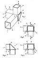
- the illustrated in Fig. 1 three-dimensional node structure consists of two hollow sections 1, 2, which together form the shape of a tripod and cohesively with each other are connected.
- the first hollow profile 1, which has a substantially square cross-section, is separated along its circumference to a web 1c and bent around the web 1c, so that two mutually facing ends 1a, 1b of the hollow profile 1 arise.
- the second hollow profile 2 has a cross section in the shape of an isosceles triangle and rests with its leg sides 2 a, 2 b at the ends 1 a, 1 b of the first hollow profile 1.
- the angle between the leg sides 2 a, 2 b corresponds to the bending angle, so that the leg sides 2 a, 2 b rest on the end faces of the ends 1 a, 1 b of the hollow profile 1 as gap-free as possible.
- the two ends 1a, 1b of the hollow profile 1 have, along their separating section, bent-over edge regions 1d, 1e, 1f which rest against the leg sides 2a, 2b of the hollow profile 2. With its front end, the hollow profile 2 closes approximately flush with the bent edge regions 1d of the ends 1a, 1b, resulting in the mentioned form of a tripod.
- the two ends 1a, 1b of the hollow profile 1 are connected at their bent edge portions 1d, 1e, 1f with the leg sides of the second hollow profile via welds 3a, 3b, 3c.
- the common edge 2c of the leg sides 2a, 2b of the hollow section 2 is connected to the web 1c of the hollow profile 1 via a weld 3d.
- Figures 2 and 3 show the node structure in a plan view, being omitted in Fig. 2 for reasons of clarity on the representation of the welds.
- Fig. 5 a-e the individual process steps for the preparation of the node structure are shown.
- Fig. 5a first by means of hydroforming a molding 1x is introduced into three sides of the hollow profile 1 along its circumference.
- the hollow profile 1 along the center of the formation 1x preferably by laser beam cutting except for a web 1c in the non-formed fourth side separated (Fig. 5b).
- the cutting tool is guided such that in the region of the edges of the hollow profile (1) over the entire edge radius extending, the edge radius correspondingly curved quadrangular cutouts (1g) are cut symmetrically to the separating cut.
- projecting edge regions 1d, 1e, 1f are produced along the separating section.
- the hollow profile 1 is bent around the web 1c by the bending angle ⁇ (FIG. 5c).
- the hollow profile 2 with its leg sides 2a, 2b, whose included angle corresponds to the bending angle ⁇ , attached to the ends 1a, 1b of the hollow section 1 ( Figure 5d), so that the projecting edge portions 1d, 1e, 1f all together abut on the leg sides 2a, 2b.
- the ends 1a, 1b of the hollow profile 1 are welded to the leg sides 2a, 2b of the hollow profile 2 at the protruding edge regions 1d, 1e, 1f.
- the web 1c is welded to the common edge 2c of the leg sides 2a, 2b.
Landscapes
- Engineering & Computer Science (AREA)
- Chemical & Material Sciences (AREA)
- Combustion & Propulsion (AREA)
- Transportation (AREA)
- Mechanical Engineering (AREA)
- Body Structure For Vehicles (AREA)
Applications Claiming Priority (3)
| Application Number | Priority Date | Filing Date | Title |
|---|---|---|---|
| DE10215442 | 2002-04-09 | ||
| DE10215442A DE10215442B4 (de) | 2002-04-09 | 2002-04-09 | Dreidimensionale Knotenstruktur |
| PCT/EP2003/003512 WO2003084800A1 (de) | 2002-04-09 | 2003-04-04 | Dreidimensionale knotenstruktur |
Publications (2)
| Publication Number | Publication Date |
|---|---|
| EP1511668A1 EP1511668A1 (de) | 2005-03-09 |
| EP1511668B1 true EP1511668B1 (de) | 2007-03-28 |
Family
ID=28684829
Family Applications (1)
| Application Number | Title | Priority Date | Filing Date |
|---|---|---|---|
| EP03720421A Expired - Lifetime EP1511668B1 (de) | 2002-04-09 | 2003-04-04 | Dreidimensionale knotenstruktur |
Country Status (9)
| Country | Link |
|---|---|
| US (1) | US7500802B2 (enExample) |
| EP (1) | EP1511668B1 (enExample) |
| JP (1) | JP4615224B2 (enExample) |
| CN (1) | CN100379632C (enExample) |
| AU (1) | AU2003224037A1 (enExample) |
| BR (1) | BR0309132B1 (enExample) |
| DE (2) | DE10215442B4 (enExample) |
| ES (1) | ES2285115T3 (enExample) |
| WO (1) | WO2003084800A1 (enExample) |
Cited By (1)
| Publication number | Priority date | Publication date | Assignee | Title |
|---|---|---|---|---|
| DE102019103182A1 (de) * | 2019-02-08 | 2020-08-13 | Man Truck & Bus Se | Gerippe-Struktur mit einer Vielzahl an Profilelementen |
Families Citing this family (43)
| Publication number | Priority date | Publication date | Assignee | Title |
|---|---|---|---|---|
| DE10215441B4 (de) | 2002-04-09 | 2004-02-19 | Thyssenkrupp Stahl Ag | Y-Knotenstruktur |
| US7353978B2 (en) * | 2005-10-13 | 2008-04-08 | The Boeing Company | Method of making tailored blanks using linear friction welding |
| ITBO20060229A1 (it) * | 2006-03-31 | 2007-10-01 | Ferrari Spa | Telaio metallico di una automobile composto da elementi estrusi. |
| DE102006036988B4 (de) * | 2006-08-08 | 2015-10-01 | Universität Kassel | Stabtragwerk zur Bildung eines Rahmens, umfassend mehrere Knoten und die Knoten verbindende Stäbe |
| US20090014993A1 (en) * | 2007-06-25 | 2009-01-15 | Mark Tope | Weight distributed low impact vehicle system capable of remote area access |
| GB2458956A (en) | 2008-04-04 | 2009-10-07 | Gordon Murray Design Ltd | Vehicle chassis |
| JP5013133B2 (ja) * | 2009-03-31 | 2012-08-29 | マツダ株式会社 | 自動車車体におけるチューブ状フレームの連結構造の組立方法 |
| US8262155B2 (en) * | 2009-12-06 | 2012-09-11 | Honda Motor Co., Ltd. | Overmolded joint for beam assembly |
| US8899868B2 (en) * | 2010-06-07 | 2014-12-02 | Roger Blaine Trivette | Miter coupling and method |
| US8533912B2 (en) * | 2011-11-29 | 2013-09-17 | Paccar Inc | Grab handle mounting assembly |
| CN104295572A (zh) * | 2013-11-09 | 2015-01-21 | 郑州宇通客车股份有限公司 | 方形型材对接方法及连接结构 |
| WO2015175892A1 (en) * | 2014-05-16 | 2015-11-19 | Divergent Microfactories, Inc. | Modular formed nodes for vehicle chassis and their methods of use |
| JP6049146B2 (ja) * | 2014-09-24 | 2016-12-21 | 富士重工業株式会社 | 車体骨格構造 |
| JP6023156B2 (ja) * | 2014-11-27 | 2016-11-09 | 日新製鋼株式会社 | Zn系めっき鋼板のアーク溶接方法 |
| USD783390S1 (en) * | 2015-02-24 | 2017-04-11 | Board By Design | Bracket |
| EP3061673B1 (de) * | 2015-02-27 | 2019-06-19 | MAGNA STEYR Fahrzeugtechnik AG & Co KG | Fahrzeugkarosserie |
| CN105857412A (zh) * | 2016-06-23 | 2016-08-17 | 北京新能源汽车股份有限公司 | 车身连接结构和具有其的车辆 |
| CN106275083B (zh) * | 2016-10-11 | 2018-10-23 | 北京长城华冠汽车科技股份有限公司 | 一种连接梁及具有该连接梁的前部框架、汽车 |
| USD823669S1 (en) * | 2017-01-31 | 2018-07-24 | Exterior Wall Systems Limited | Five-way cube connector for wall panel system |
| USD827416S1 (en) * | 2017-01-31 | 2018-09-04 | Exterior Wall Systems Limited | Three-legged cube connector for wall panel system |
| USD839075S1 (en) * | 2017-01-31 | 2019-01-29 | Exterior Wall Systems Limited | Tee cube connector for wall panel system |
| USD823668S1 (en) * | 2017-01-31 | 2018-07-24 | Exterior Wall Systems Limited (Ontario Panelization) | Pyramid cap connector for wall panel system |
| USD823666S1 (en) * | 2017-01-31 | 2018-07-24 | Exterior Wall Systems Limited | Two-legged cube connector for wall panel system |
| USD823670S1 (en) * | 2017-01-31 | 2018-07-24 | Exterior Wall Systems Limited | Two-legged cube connector for wall panel system |
| USD826692S1 (en) * | 2017-01-31 | 2018-08-28 | Exterior Wall Systems Limited | Four-way cube connector for wall panel system |
| USD823667S1 (en) * | 2017-01-31 | 2018-07-24 | Exterior Wall Systems Limited | Three-legged cube connector for wall panel system |
| US20180238041A1 (en) | 2017-02-21 | 2018-08-23 | Styrc Jacek | Modular furniture system |
| USD887025S1 (en) | 2017-11-17 | 2020-06-09 | 2724889 Ontario Inc. | Connector for a modular structure |
| US10612577B2 (en) | 2018-03-28 | 2020-04-07 | Board By Design | Table bracket |
| USD938771S1 (en) | 2020-02-04 | 2021-12-21 | 2724889 Ontario Inc. | Connector |
| USD938772S1 (en) | 2020-02-04 | 2021-12-21 | 2724889 Ontario Inc. | Connector |
| USD936859S1 (en) | 2020-02-04 | 2021-11-23 | 2724889 Ontario Inc. | Connector |
| USD952382S1 (en) | 2020-02-04 | 2022-05-24 | 2724889 Ontario Inc. | Table |
| USD938770S1 (en) | 2020-02-04 | 2021-12-21 | 2724889 Ontario Inc. | Connector |
| USD952384S1 (en) | 2020-02-04 | 2022-05-24 | 2724889 Ontario Inc. | Leg |
| USD936861S1 (en) | 2020-08-12 | 2021-11-23 | 2724889 Ontario Inc. | Connector for a modular structure |
| USD936246S1 (en) | 2020-08-12 | 2021-11-16 | 2724889 Ontario Inc. | Connector for a modular structure |
| USD939106S1 (en) | 2020-08-12 | 2021-12-21 | 2724889 Ontario Inc. | Connector for a modular structure |
| USD936247S1 (en) | 2020-08-12 | 2021-11-16 | 2724889 Ontario Inc. | Connector for a modular structure |
| USD938068S1 (en) | 2020-08-12 | 2021-12-07 | 2724889 Ontario Inc. | Connector for a modular structure |
| USD938619S1 (en) | 2020-08-12 | 2021-12-14 | 2724889 Ontario Inc. | Connector for a modular structure |
| USD939731S1 (en) | 2020-08-12 | 2021-12-28 | 2724889 Ontario Inc. | Connector for a modular structure |
| DE102021133018B3 (de) | 2021-12-14 | 2022-07-14 | Strothmann Machines & Handling GmbH | Fertigungsverfahren einer Linearachse, Strukturelement und Strukturteil |
Family Cites Families (23)
| Publication number | Priority date | Publication date | Assignee | Title |
|---|---|---|---|---|
| US809061A (en) * | 1905-02-04 | 1906-01-02 | Henry Howe Hoover | Chair. |
| US1601140A (en) * | 1924-01-29 | 1926-09-28 | Jr Thomas E Murray | Automobile frame |
| US1972309A (en) * | 1932-08-17 | 1934-09-04 | Standard Gas Equipment Corp | Metal tubular frame structure and method of fabricating the same |
| US2193298A (en) * | 1938-10-11 | 1940-03-12 | Truscon Steel Co | Method of producing muntin bar structures |
| US2387134A (en) * | 1941-01-16 | 1945-10-16 | Fox John Jay | Method of forming t-head columns |
| DE894508C (de) | 1942-04-01 | 1953-10-26 | Daimler Benz Ag | Aus geschlossenen, kastenfoermigen Hohltraegern bestehendes Wagenkastengerippe, insbesondere fuer Grossraumfahrzeuge |
| CH293838A (de) | 1942-04-01 | 1953-10-15 | Daimler Benz Ag | Verdrehungssteifer Wagenkasten, insbesondere für Grossraumfahrzeuge. |
| GB1559178A (en) | 1975-12-04 | 1980-01-16 | Massey Ferguson Services Nv | Structural joints |
| US4694547A (en) * | 1984-02-27 | 1987-09-22 | Broussard Edison L | One-piece metal covering for insulated pipe bends |
| DE3726079A1 (de) * | 1987-08-06 | 1989-02-16 | Man Nutzfahrzeuge Gmbh | Tuerrahmen an nutzfahrzeugen, insbesondere omnibussen, mit einem aus vertikal- und horizontaltraegern bestehenden gerippe aus hohlprofilen |
| KR100199537B1 (ko) | 1989-03-07 | 1999-06-15 | 데이비드 더블유. 브라운리 | 압출된 접속구 |
| DE3918283C1 (enExample) | 1989-06-05 | 1990-05-31 | Audi Ag, 8070 Ingolstadt, De | |
| US5226698A (en) * | 1991-11-05 | 1993-07-13 | Harrison Betty L | Harness for securing an object to a support and method of use thereof |
| US5228259A (en) * | 1992-04-29 | 1993-07-20 | Ford Motor Company | Space frame connector |
| US5332281A (en) * | 1992-04-30 | 1994-07-26 | Ford Motor Company | Space frame construction |
| US5190207A (en) * | 1992-06-02 | 1993-03-02 | Deere & Company | Method for welding rectangular tubes |
| DE4337517A1 (de) * | 1993-11-03 | 1995-05-04 | Klaas Friedrich | Verfahren zum Innenhochdruck-Umformen von hohlen abgesetzten Wellen aus kaltumformbarem Metall |
| JPH0861329A (ja) | 1994-08-22 | 1996-03-08 | Showa Alum Corp | アルミニウム製押出材同士の継手構造 |
| DE19724037C2 (de) | 1997-06-06 | 2000-08-31 | Audi Ag | Verfahren zum Schneiden eines Hohlkörpers |
| JPH11254178A (ja) * | 1998-03-09 | 1999-09-21 | Yutani Heavy Ind Ltd | 溶接強度構造物 |
| US6361244B1 (en) * | 2000-02-24 | 2002-03-26 | General Motors Corporation | Hydroformed tubular structures and methods of making |
| US6241310B1 (en) * | 2000-05-17 | 2001-06-05 | Asc Incorporated | Vehicle structure with integral node |
| DE10215441B4 (de) * | 2002-04-09 | 2004-02-19 | Thyssenkrupp Stahl Ag | Y-Knotenstruktur |
-
2002
- 2002-04-09 DE DE10215442A patent/DE10215442B4/de not_active Expired - Fee Related
-
2003
- 2003-04-04 JP JP2003582016A patent/JP4615224B2/ja not_active Expired - Fee Related
- 2003-04-04 BR BRPI0309132-5A patent/BR0309132B1/pt not_active IP Right Cessation
- 2003-04-04 AU AU2003224037A patent/AU2003224037A1/en not_active Abandoned
- 2003-04-04 ES ES03720421T patent/ES2285115T3/es not_active Expired - Lifetime
- 2003-04-04 EP EP03720421A patent/EP1511668B1/de not_active Expired - Lifetime
- 2003-04-04 WO PCT/EP2003/003512 patent/WO2003084800A1/de not_active Ceased
- 2003-04-04 CN CNB038125250A patent/CN100379632C/zh not_active Expired - Fee Related
- 2003-04-04 US US10/509,587 patent/US7500802B2/en not_active Expired - Lifetime
- 2003-04-04 DE DE50306910T patent/DE50306910D1/de not_active Expired - Lifetime
Cited By (1)
| Publication number | Priority date | Publication date | Assignee | Title |
|---|---|---|---|---|
| DE102019103182A1 (de) * | 2019-02-08 | 2020-08-13 | Man Truck & Bus Se | Gerippe-Struktur mit einer Vielzahl an Profilelementen |
Also Published As
| Publication number | Publication date |
|---|---|
| AU2003224037A1 (en) | 2003-10-20 |
| DE10215442A1 (de) | 2003-11-06 |
| EP1511668A1 (de) | 2005-03-09 |
| ES2285115T3 (es) | 2007-11-16 |
| WO2003084800A1 (de) | 2003-10-16 |
| JP4615224B2 (ja) | 2011-01-19 |
| DE50306910D1 (de) | 2007-05-10 |
| US20060029462A1 (en) | 2006-02-09 |
| US7500802B2 (en) | 2009-03-10 |
| DE10215442B4 (de) | 2004-02-19 |
| JP2005527421A (ja) | 2005-09-15 |
| BR0309132A (pt) | 2005-02-01 |
| BR0309132B1 (pt) | 2012-11-27 |
| CN1655978A (zh) | 2005-08-17 |
| CN100379632C (zh) | 2008-04-09 |
Similar Documents
| Publication | Publication Date | Title |
|---|---|---|
| EP1511668B1 (de) | Dreidimensionale knotenstruktur | |
| EP1654150B1 (de) | Knotenstruktur zur verbindung von zwei profilen in einem fahrzeugtragrahmen | |
| DE102018119735B4 (de) | Stoßfängerquerträger für ein Kraftfahrzeug | |
| DE69032545T2 (de) | Extrudierter knotenpunkt | |
| DE19733470C1 (de) | Vorzugsweise U-förmiger Profilträger, insbesondere Rahmenlängsträger, für einen Tragrahmen eines Nutzfahrzeuges und Verfahren zu seiner Herstellung | |
| DE102004019089B4 (de) | Fahrzeugkarosserieaufbau | |
| EP1492694B1 (de) | Y-knotenstruktur eines tragrahmens für fahrzeuge | |
| DE19622661A1 (de) | Verfahren zur Herstellung eines Fahrzeugrahmens | |
| EP1448430A1 (de) | Aus stahlblech bestehender verbindungsknoten von aus stahlblech bestehenden profilen | |
| DE69800803T2 (de) | Verfahren zum aneinander verbinden zwei rohrformige werkstücken sowie mechanischer bauteil aus zwei verbundenen rohrformigen werkstücken | |
| DE19609722B4 (de) | Verfahren zum Verbinden zweier metallischer Profile, insbesondere zweier stranggepreßter Aluminiumprofilteile | |
| EP1583684B1 (de) | Längsträger für ein fahrzeug | |
| EP0780286B1 (de) | Trägeranordnung | |
| DE10225577C1 (de) | Verzweigte Knotenstruktur | |
| DE102007041221B3 (de) | Verfahren zum Herstellen einer Klemmleiste | |
| DE102004011252B3 (de) | Fahrzeugrahmen | |
| EP3281836B1 (de) | Hohlkammerprofil für eine wagenkastenstruktur eines schienenfahrzeugs sowie schienenfahrzeug | |
| EP4606681B1 (de) | Verbindung eines achshilfsrahmens mit einem längsprofil | |
| DE102020132481B4 (de) | Energieabsorptionsvorrichtung für eine Stoßfängeranordnung eines Kraftfahrzeuges sowie Stoßfängeranordnung eines Kraftfahrzeuges | |
| WO2005030562A1 (de) | Rahmenstruktur und verfahren zu deren herstellung | |
| DE102015100997B4 (de) | Verbindungsanordnung eines ersten Karosseriebauteils an einem zweiten Karosseriebauteil für ein Kraftfahrzeug, insbesondere Personenkraftfahrzeug | |
| EP0827873B1 (de) | Verfahren zur Herstellung eines Trägers | |
| EP1758707B1 (de) | Verfahren zum herstellen einer rahmenstruktur mit mindestens zwei hohlprofilelementen | |
| WO2024179626A1 (de) | STOßFÄNGERVERSTÄRKUNG | |
| DE19641665A1 (de) | Klemmleiste für die Innendachbespannung zur Verwendung bei Fahrzeugen mit Schiebedach sowie Verfahren zu deren Herstellung |
Legal Events
| Date | Code | Title | Description |
|---|---|---|---|
| PUAI | Public reference made under article 153(3) epc to a published international application that has entered the european phase |
Free format text: ORIGINAL CODE: 0009012 |
|
| 17P | Request for examination filed |
Effective date: 20041005 |
|
| AK | Designated contracting states |
Kind code of ref document: A1 Designated state(s): AT BE BG CH CY CZ DE DK EE ES FI FR GB GR HU IE IT LI LU MC NL PT RO SE SI SK TR |
|
| AX | Request for extension of the european patent |
Extension state: AL LT LV MK |
|
| RAP1 | Party data changed (applicant data changed or rights of an application transferred) |
Owner name: THYSSENKRUPP STEEL AG |
|
| GRAP | Despatch of communication of intention to grant a patent |
Free format text: ORIGINAL CODE: EPIDOSNIGR1 |
|
| GRAS | Grant fee paid |
Free format text: ORIGINAL CODE: EPIDOSNIGR3 |
|
| GRAA | (expected) grant |
Free format text: ORIGINAL CODE: 0009210 |
|
| AK | Designated contracting states |
Kind code of ref document: B1 Designated state(s): CZ DE ES FR GB IT |
|
| REG | Reference to a national code |
Ref country code: GB Ref legal event code: FG4D Free format text: NOT ENGLISH |
|
| REF | Corresponds to: |
Ref document number: 50306910 Country of ref document: DE Date of ref document: 20070510 Kind code of ref document: P |
|
| GBT | Gb: translation of ep patent filed (gb section 77(6)(a)/1977) |
Effective date: 20070622 |
|
| ET | Fr: translation filed | ||
| REG | Reference to a national code |
Ref country code: ES Ref legal event code: FG2A Ref document number: 2285115 Country of ref document: ES Kind code of ref document: T3 |
|
| PLBE | No opposition filed within time limit |
Free format text: ORIGINAL CODE: 0009261 |
|
| STAA | Information on the status of an ep patent application or granted ep patent |
Free format text: STATUS: NO OPPOSITION FILED WITHIN TIME LIMIT |
|
| 26N | No opposition filed |
Effective date: 20080102 |
|
| PGFP | Annual fee paid to national office [announced via postgrant information from national office to epo] |
Ref country code: CZ Payment date: 20090306 Year of fee payment: 7 |
|
| PGFP | Annual fee paid to national office [announced via postgrant information from national office to epo] |
Ref country code: ES Payment date: 20090424 Year of fee payment: 7 |
|
| PGFP | Annual fee paid to national office [announced via postgrant information from national office to epo] |
Ref country code: FR Payment date: 20090422 Year of fee payment: 7 Ref country code: IT Payment date: 20090428 Year of fee payment: 7 |
|
| PGFP | Annual fee paid to national office [announced via postgrant information from national office to epo] |
Ref country code: GB Payment date: 20090422 Year of fee payment: 7 |
|
| GBPC | Gb: european patent ceased through non-payment of renewal fee |
Effective date: 20100404 |
|
| REG | Reference to a national code |
Ref country code: FR Ref legal event code: ST Effective date: 20101230 |
|
| PG25 | Lapsed in a contracting state [announced via postgrant information from national office to epo] |
Ref country code: CZ Free format text: LAPSE BECAUSE OF NON-PAYMENT OF DUE FEES Effective date: 20100404 |
|
| PG25 | Lapsed in a contracting state [announced via postgrant information from national office to epo] |
Ref country code: GB Free format text: LAPSE BECAUSE OF NON-PAYMENT OF DUE FEES Effective date: 20100404 Ref country code: IT Free format text: LAPSE BECAUSE OF NON-PAYMENT OF DUE FEES Effective date: 20100404 |
|
| REG | Reference to a national code |
Ref country code: ES Ref legal event code: FD2A Effective date: 20110712 |
|
| PG25 | Lapsed in a contracting state [announced via postgrant information from national office to epo] |
Ref country code: ES Free format text: LAPSE BECAUSE OF NON-PAYMENT OF DUE FEES Effective date: 20110630 |
|
| PG25 | Lapsed in a contracting state [announced via postgrant information from national office to epo] |
Ref country code: ES Free format text: LAPSE BECAUSE OF NON-PAYMENT OF DUE FEES Effective date: 20100405 |
|
| PG25 | Lapsed in a contracting state [announced via postgrant information from national office to epo] |
Ref country code: FR Free format text: LAPSE BECAUSE OF NON-PAYMENT OF DUE FEES Effective date: 20100430 |
|
| PGFP | Annual fee paid to national office [announced via postgrant information from national office to epo] |
Ref country code: DE Payment date: 20200420 Year of fee payment: 18 |
|
| REG | Reference to a national code |
Ref country code: DE Ref legal event code: R119 Ref document number: 50306910 Country of ref document: DE |
|
| PG25 | Lapsed in a contracting state [announced via postgrant information from national office to epo] |
Ref country code: DE Free format text: LAPSE BECAUSE OF NON-PAYMENT OF DUE FEES Effective date: 20211103 |