EP1511196A2 - Un schéma pour réduire les composantes basse-fréquence dans un réseau de transmission optique - Google Patents
Un schéma pour réduire les composantes basse-fréquence dans un réseau de transmission optique Download PDFInfo
- Publication number
- EP1511196A2 EP1511196A2 EP04019898A EP04019898A EP1511196A2 EP 1511196 A2 EP1511196 A2 EP 1511196A2 EP 04019898 A EP04019898 A EP 04019898A EP 04019898 A EP04019898 A EP 04019898A EP 1511196 A2 EP1511196 A2 EP 1511196A2
- Authority
- EP
- European Patent Office
- Prior art keywords
- optical
- transmission network
- optical transmission
- low frequency
- operable
- Prior art date
- Legal status (The legal status is an assumption and is not a legal conclusion. Google has not performed a legal analysis and makes no representation as to the accuracy of the status listed.)
- Withdrawn
Links
Images


Classifications
-
- H—ELECTRICITY
- H04—ELECTRIC COMMUNICATION TECHNIQUE
- H04B—TRANSMISSION
- H04B10/00—Transmission systems employing electromagnetic waves other than radio-waves, e.g. infrared, visible or ultraviolet light, or employing corpuscular radiation, e.g. quantum communication
- H04B10/50—Transmitters
- H04B10/501—Structural aspects
- H04B10/503—Laser transmitters
- H04B10/505—Laser transmitters using external modulation
- H04B10/5055—Laser transmitters using external modulation using a pre-coder
-
- H—ELECTRICITY
- H04—ELECTRIC COMMUNICATION TECHNIQUE
- H04B—TRANSMISSION
- H04B10/00—Transmission systems employing electromagnetic waves other than radio-waves, e.g. infrared, visible or ultraviolet light, or employing corpuscular radiation, e.g. quantum communication
- H04B10/25—Arrangements specific to fibre transmission
- H04B10/2507—Arrangements specific to fibre transmission for the reduction or elimination of distortion or dispersion
- H04B10/2513—Arrangements specific to fibre transmission for the reduction or elimination of distortion or dispersion due to chromatic dispersion
- H04B10/25137—Arrangements specific to fibre transmission for the reduction or elimination of distortion or dispersion due to chromatic dispersion using pulse shaping at the transmitter, e.g. pre-chirping or dispersion supported transmission [DST]
-
- H—ELECTRICITY
- H04—ELECTRIC COMMUNICATION TECHNIQUE
- H04B—TRANSMISSION
- H04B10/00—Transmission systems employing electromagnetic waves other than radio-waves, e.g. infrared, visible or ultraviolet light, or employing corpuscular radiation, e.g. quantum communication
- H04B10/50—Transmitters
- H04B10/516—Details of coding or modulation
Definitions
- the present invention generally relates to optical transmission networks. More particularly, and not by way of any limitation, the present invention is directed to a scheme for reducing low frequency components in an optical transmission network.
- Modulating a digital lightwave output generates the digital "1"'s and digital "0'" s that are transmitted, and hence determines the content and integrity of the digital signal. From an economic viewpoint, the distance that can be spanned between a transmitter and a receiver, while maintaining data integrity, determines the expenditures that must be made to physically lay fiber in the ground or to install repeaters and other supporting equipment.
- One way to control the output of a transmitter disposed in a digital lightwave communications system is to directly modulate the light source, e.g., a laser source.
- the laser could be turned on and off at intervals, thus generating digital 1's (when the light source is on) and digital 0's (when the light source is off). This can be accomplished by turning the current to the laser on and off. While this method may work in lower speed applications, in high-speed digital lightwave communications it is not practical to directly modulate the output of the laser because, as the current to the laser is changed, the wavelengths of the laser outputs are also slightly changed.
- Direct laser modulation could thus cause significant dispersion in each of the different wavelengths-traveling along a fiber optic cable, resulting in noise and data corruption at the far end (i.e., receiver end) of a high-speed digital lightwave system.
- WDM Wavelength Division Multiplexing
- a significant amount of noise also results from carrying multiple wavelengths on a single fiber. This can result in loss of receiver sensitivity, because it is more difficult for the receiver to distinguish between the digital 1's and 0's, and hence to interpret the data carried by the signal.
- Modulators do not affect the wavelengths carrying the data signal as much as direct modulation.
- these modulators require a data amplitude input (which data is typically in the range of one or more Gigabits per second (Gbps), i.e., in the radio frequency or RF range) and bias point that must be set and maintained at or near an optimum value for each modulator. Otherwise, the resulting wavelength shift in the transmitted data, along with the inherent noise and dispersion prevalent in lightwave transmission systems, can result in the signals received at the receiver being noisy and difficult to differentiate.
- Gbps Gigabits per second
- the aforementioned shortcomings are further exacerbated by the use of non-optimized optical filter components in a fiber transmission path.
- specific components of an optical signal are required to be transmitted, only perfectly centered and matched filters need to be used so that there is no signal dispersion in the unwanted regions of the power spectrum.
- the requirement of such centered optics optimized for a particular transmission application not only imposes stringent economic constraints, but is impractical in the long run as well, since the optical characteristics of the components may vary over time.
- the present invention advantageously provides a scheme for reducing undesirable components in optical signals in an optical transmission network.
- a block coding scheme is implemented that is matched to the spectral characteristics of one or more optical components of a transmission path, e.g., filters, optical media, et cetera, whereby the source data is encoded for shifting the power density spectra of the optical signals into a more desirable band.
- the present invention is directed to an optical transmission network wherein low frequency components associated with the optical signals are suppressed.
- a data source is provided as part of a transmitter system for generating data operable to be transmitted via an optical transmission medium.
- a block encoder associated with the data source is operable to encode the data signals generated by the data source.
- the transmitter system also includes a modulator for modulating an optical source based on the encoded data.
- An optical filter component is provided for filtering a portion of a power spectral density function associated with the modulator's output.
- a receiver system coupled to the optical transmission medium includes a demodulator and a block decoder that correspond, respectively, to the transmitter system's modulator and block encoder, wherein the block encoder is operable to encode the data signals such that low frequency components are suppressed in the optical filter's output.
- the present invention is directed to an integrated modulator system for an optical signal based on a digital data signal.
- the modulator system comprises a filter with a passband for filtering the optical signal and a block encoder operating on the digital data signal for suppressing spectral density of at least a portion of the optical signal based on the filter's passband.
- the present invention is directed to a method for reducing low frequency components in an optical transmission network.
- the method includes the operation of determining optical characteristics of a filter component disposed in the optical transmission network. A determination is made with respect to a cut-off region of a power spectral density function associated with the filter component's output.
- a matching block encoder is implemented wherein the block encoder is operable to encode digital data generated by a data source such that low frequency power spectra are suppressed in the cut-off region of the power spectral density function associated with the filter component.
- the various operations of the claimed method may be implemented in suitable structural components comprising hardware, firmware, or software, or any combination thereof.
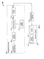
- a transmitter system 102 comprises an electrical data source 106 operable to generate digital pulse train data which can be in any known format such as, e.g., the Non-Return-to-Zero (NRZ) or Return-to-Zero (RZ) format.
- NRZ Non-Return-to-Zero
- RZ Return-to-Zero
- An optical modulator 108 is operable to modulate a laser source 110 based on the digital electrical data so as to generate modulated data suitable for transmission via an optical medium 114.
- An optical filter block 112 is disposed thereafter to shape the power spectral density (PSD) of the modulator output (S MOD ) such that only a portion of the PSD function, preferably having only the desired components representing the full bandwidth of the data signal, is transmitted via the optical medium 114.
- a receiver system 104 disposed at the receiving end of the transmission network 100 is provided with appropriate optical components, opto-electrical components, and electrical components to effectuate signal reception, demodulation/conversion and the like.
- components such as optical filters do not typically exhibit optimal (or, ideal) performance characteristics, especially over a long period of time.
- their transfer functions operate on input PSD functions in a fashion that gives rise to output signals having components that are not optimized for transmission, thereby resulting in overall system inefficiency.
- Such concerns are particularly exacerbated where specific portions of a PSD function associated with the output of a modulator are required to be shaped in a predetermined fashion.
- FIG. 2A depicts an exemplary PSD function associated with the output of a modulator conventionally disposed in an optical transmission network, e.g., modulator 108 of the network 100 described hereinabove.
- a modulator conventionally disposed in an optical transmission network
- modulator 108 of the network 100 described hereinabove.
- conventional intensity modulation creates an optical spectrum that is mirror-imaged around a carrier wave.
- Reference numeral 202 refers to the PSD function, S MOD , associated with the modulator 108 that is centered around the carrier frequency (f c ) within a bandwidth defined by lower and higher frequency limits (f MIN and f MAX ).
- the spectrum on either side of the carrier frequency is mutually redundant, since only one side (i.e., sideband) is actually needed to represent all the data generated by a data source disposed in the optical transmission network.
- sideband only one side (i.e., sideband) is actually needed to represent all the data generated by a data source disposed in the optical transmission network.
- reference numerals 204A and 204B refer to the two sidebands, Sideband-A and Sideband-B, of the S MOD spectrum 202. Because of the spectral redundancy, known techniques such as Vestigial Sideband (VSB) transmission attempt to provide only one half of the bandwidth, namely, the higher frequency Sideband-B 204B, for downstream transmission by filtering out the other half, i.e., the lower frequency Sideband-A 204A. Since the filtering process is less than ideal (due to the non-optimal characteristics of a filter component typically deployed), the resulting PSD function associated with the optical filter output (S OF ), usually contains a lower frequency component.
- FIG. 2B depicts an exemplary PSD function 206 associated with the output of a non-optimized filter disposed in an optical transmission network, e.g., filter 112 of the network 100 set forth above.
- the PSD function 206 includes a low frequency component 208 that is also transmitted via the optical medium, thereby negatively impacting the overall efficiency of the optical transmission network. Additional details regarding the VSB transmission technique may be found in the following commonly owned co-pending patent application: "Optical Vestigial Sideband Transmitter/Receiver," Application No. 10/173,378, filed June 17, 2002 (Alcatel Docket Number 139016), cross-referenced hereinabove.
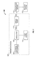
- a transmitter system 302 includes an electrical data source 306 operable to generate digital pulse train data (e.g., digital data having the Non-Return-to-Zero (NRZ) or Return-to-Zero (RZ) format).
- digital pulse train data e.g., digital data having the Non-Return-to-Zero (NRZ) or Return-to-Zero (RZ) format.
- a block encoder 308 is provided for encoding the digital data generated by the data source 306 in a manner such that the cumulative transfer function characteristics of a non-optimized optical filtering process of the transmission network are taken into account for generating a power spectrum that is devoid of low frequency components.
- Any known or heretofore unknown optical modulator 308 e.g., a Mach-Zehnder modulator
- the optical source 312 may comprise a Continuous-Wave (CW) laser source. Additionally, depending on implementation requirements, the optical source 312 may comprise a.low chirp or high chirp laser system.
- An optical filter component 314 is provided to shape the power spectral density (PSD) of the modulated output (S * MOD ) such that only the desired region thereof is filtered for transmission.
- a receiver system 304 disposed at the receiving end of the transmission network 300 is provided with appropriate components such as demodulator 316 and block decoder 318, in addition to other related optoelectronics, for processing the received data.
- the optical filter 314 is shown to be associated with the transmitter system 302 of the optical transmission network 300, it should be apparent that in a different embodiment the filtering functionality may be co-located at the receiving system 304, in which case both sidebands of the S * MOD power density function are transmitted through the optical medium 316.
- the block encoder 308 is preferably designed to compensate for the non-optimized characteristics of one or more optical components of a transmission path, which can include filter components, physical media components, and the like.
- a transmission path which can include filter components, physical media components, and the like.
- Any known or heretofore unknown block coding scheme may be used in accordance with the teachings of the present invention, which coding scheme can be implemented in a suitable hardware/firmware realization (e.g., a gate array chip set or an application-specific integrated circuit), for shaping the digital data signals to counteract the effect of a non-optimized optical component.
- block code generators may be provided in a functional block that can be programmed, on an as-needed basis, to select a particular coding scheme that is appropriate for a given filter/media component combination.
- the block encoder may be operable to be programmed into an OFF condition, based on the spectral characteristics of the filter used.
- block coding is an mb/nb binary coding method that maps m binary bits of data to blocks having n bits each for transmission, where m ⁇ n.
- binary coding schemes such as 3b4b or 7b8b schemes may be implemented that are tuned to the spectral characteristics of the optical components of a particular transmission network.
- FIG. 4 depicts exemplary PSD functions associated with the optical transmission network 300 of FIG. 3 upon employing a suitable block coding scheme.
- Reference numeral 402 refers to the PSD function (S * MOD ) associated with the modulated encoded data output.
- Reference numeral 404 refers to the PSD function (S * OF ) associated with the output of the non-optimized optical filter disposed in the transmission network.
- FIG. 5 is a flow chart of an embodiment of a method of the present invention for implementing a scheme capable of suppressing low frequency components in an optical transmission network.
- transfer function characteristics of the various constituent optical components are determined and parameterized (block 502).
- filter passband functionality et cetera
- a requisite cut-off region e.g., a low frequency region
- a matching block encoder/decoder is implemented in the transmission path (encoding at the source and decoding at the destination) that is designed to suppress the spectral components in the requisite cut-off region of the PSD function of the transmission system (block 506).
- appropriate hardware/software structures . may be implemented in an optical node having advanced capabilities for automatically executing the aforesaid procedures as and when needed (for instance, where the optical characteristics of a filter vary over time, when a new filter is installed, and the like).
- Reference numeral 602 refers to the input to the block encoder which comprises eight 3-bit chunks of the digital data provided by a data source.
- the encoder's output 604, which transitions between two states, STATE-1 606 and STATE-2 608, comprises 4-bit nibbles, each encoding a particular 3-bit input chunk. As long as balanced 4-bit output nibbles are transmitted, the encoder does not change its state, as exemplified by the state transition diagram of FIG. 6B.
- the described and claimed integrated modulator system for an optical signal based on a digital data signal may have one or more of the following advantageous features:
- the present invention advantageously provides a scheme for reducing the effect of non-optimized optical components disposed in a transmission network by matching their performance characteristics with a suitable block coding technique. It is believed that the operation and construction of the present invention will be apparent from the foregoing Detailed Description. While one or more of the exemplary embodiments of the invention shown and described have been characterized as being preferred, it should be readily understood that various changes and modifications could be made therein without departing from the scope of the present invention as set forth in the following claims. For instance, it should be appreciated that the optical transmission network of the present invention may be implemented as part of a long-haul network or a short-haul network, using such techniques as Wavelength Division Multiplexing.
- circuitry for source sampling, other channel and/or line coding, sample quantization, etc. may also be included as part of an exemplary optical transmission network.
- teachings of the present invention may be practiced in conjunction with a variety of laser sources, modulators, optical filters and transmission media, with any level of component and system integration.
- the block encoding functionality may be built into an integrated modulator unit at the source. A further level of integration may result in a modulator system having the optical filter functionality incorporated therein.
- an integrated modulator/laser may be used as an optical source. Accordingly, all these and other related additions, variations, substitutions, modifications, and embodiments are deemed to be in the ambit of the present invention defined solely by the claims appended immediately below.
Landscapes
- Physics & Mathematics (AREA)
- Electromagnetism (AREA)
- Engineering & Computer Science (AREA)
- Computer Networks & Wireless Communication (AREA)
- Signal Processing (AREA)
- Optics & Photonics (AREA)
- Optical Communication System (AREA)
Applications Claiming Priority (2)
| Application Number | Priority Date | Filing Date | Title |
|---|---|---|---|
| US651158 | 2000-08-30 | ||
| US10/651,158 US20050047793A1 (en) | 2003-08-28 | 2003-08-28 | Scheme for reducing low frequency components in an optical transmission network |
Publications (2)
| Publication Number | Publication Date |
|---|---|
| EP1511196A2 true EP1511196A2 (fr) | 2005-03-02 |
| EP1511196A3 EP1511196A3 (fr) | 2008-02-13 |
Family
ID=34104727
Family Applications (1)
| Application Number | Title | Priority Date | Filing Date |
|---|---|---|---|
| EP04019898A Withdrawn EP1511196A3 (fr) | 2003-08-28 | 2004-08-23 | Un schéma pour réduire les composantes basse-fréquence dans un réseau de transmission optique |
Country Status (2)
| Country | Link |
|---|---|
| US (1) | US20050047793A1 (fr) |
| EP (1) | EP1511196A3 (fr) |
Cited By (1)
| Publication number | Priority date | Publication date | Assignee | Title |
|---|---|---|---|---|
| CN110868220A (zh) * | 2018-08-28 | 2020-03-06 | 株洲中车时代电气股份有限公司 | 车辆设备的身份标识的配置及异常检测方法 |
Families Citing this family (6)
| Publication number | Priority date | Publication date | Assignee | Title |
|---|---|---|---|---|
| US7689132B2 (en) * | 2005-06-07 | 2010-03-30 | Industrial Technology Research Institute | Interference-rejection coding method for an optical wireless communication system and the optical wireless communication system thereof |
| US9203522B2 (en) * | 2008-08-19 | 2015-12-01 | Finisar Corporation | Phase lock loop control for digital communication systems |
| US9905236B2 (en) * | 2012-03-23 | 2018-02-27 | Dolby Laboratories Licensing Corporation | Enabling sampling rate diversity in a voice communication system |
| EP2701324A1 (fr) * | 2012-08-22 | 2014-02-26 | Xieon Networks S.à.r.l. | Procédé et dispositif pour le transport de données optiques |
| EP3107096A1 (fr) | 2015-06-16 | 2016-12-21 | Fraunhofer-Gesellschaft zur Förderung der angewandten Forschung e.V. | Décodage à échelle réduite |
| DE102015221283B4 (de) * | 2015-10-30 | 2017-09-14 | Deutsches Zentrum für Luft- und Raumfahrt e.V. | Sender für ein optisches Freistrahl-Kommunikations-System und zugehöriges Empfängerterminal |
Citations (3)
| Publication number | Priority date | Publication date | Assignee | Title |
|---|---|---|---|---|
| EP1202476A1 (fr) * | 2000-10-27 | 2002-05-02 | Alcatel | Système et émetteur pour la transmission de données optiques |
| WO2002061978A1 (fr) * | 2001-01-29 | 2002-08-08 | Stratalight Communications, Inc. | Transmission et reception de signaux optiques duobinaires multiniveaux a modulation d'impulsions en amplitude au moyen d'un codeur soustractif |
| US6542276B1 (en) * | 1998-08-28 | 2003-04-01 | Lucent Technologies Inc. | Method and apparatus for increasing the spectral efficiency of dense wavelength division multiplexed systems |
Family Cites Families (5)
| Publication number | Priority date | Publication date | Assignee | Title |
|---|---|---|---|---|
| US6029058A (en) * | 1996-07-19 | 2000-02-22 | The Board Of Trustee Of The Leland Stanford Junior University | Spectrum control for direct conversion radio frequency reception |
| US6973140B2 (en) * | 1999-03-05 | 2005-12-06 | Ipr Licensing, Inc. | Maximizing data rate by adjusting codes and code rates in CDMA system |
| US6473214B1 (en) * | 1999-04-01 | 2002-10-29 | Nortel Networks Limited | Methods of and apparatus for optical signal transmission |
| US6661976B1 (en) * | 2000-01-05 | 2003-12-09 | At&T Corp. | Method and system for single-sideband optical signal generation and transmission |
| US20030058509A1 (en) * | 2001-09-24 | 2003-03-27 | Ditech Communications Corporation | Optical vestigial sideband (VSB) transmission |
-
2003
- 2003-08-28 US US10/651,158 patent/US20050047793A1/en not_active Abandoned
-
2004
- 2004-08-23 EP EP04019898A patent/EP1511196A3/fr not_active Withdrawn
Patent Citations (3)
| Publication number | Priority date | Publication date | Assignee | Title |
|---|---|---|---|---|
| US6542276B1 (en) * | 1998-08-28 | 2003-04-01 | Lucent Technologies Inc. | Method and apparatus for increasing the spectral efficiency of dense wavelength division multiplexed systems |
| EP1202476A1 (fr) * | 2000-10-27 | 2002-05-02 | Alcatel | Système et émetteur pour la transmission de données optiques |
| WO2002061978A1 (fr) * | 2001-01-29 | 2002-08-08 | Stratalight Communications, Inc. | Transmission et reception de signaux optiques duobinaires multiniveaux a modulation d'impulsions en amplitude au moyen d'un codeur soustractif |
Non-Patent Citations (1)
| Title |
|---|
| FARAJ P ET AL: "Coding gain of basic fec block-codes in the presence of ase noise" TRANSPARENT OPTICAL NETWORKS, 2003. PROCEEDINGS OF 2003 5TH INTERNATIONAL CONFERENCE ON WARSAW, POLAND 29 JUNE-3 JULY 2003, PISCATAWAY, NJ, USA,IEEE, US, vol. 2, 29 June 2003 (2003-06-29), pages 80-83, XP010680698 ISBN: 0-7803-7816-4 * |
Cited By (2)
| Publication number | Priority date | Publication date | Assignee | Title |
|---|---|---|---|---|
| CN110868220A (zh) * | 2018-08-28 | 2020-03-06 | 株洲中车时代电气股份有限公司 | 车辆设备的身份标识的配置及异常检测方法 |
| CN110868220B (zh) * | 2018-08-28 | 2021-09-07 | 株洲中车时代电气股份有限公司 | 车辆设备的身份标识的配置及异常检测方法 |
Also Published As
| Publication number | Publication date |
|---|---|
| EP1511196A3 (fr) | 2008-02-13 |
| US20050047793A1 (en) | 2005-03-03 |
Similar Documents
| Publication | Publication Date | Title |
|---|---|---|
| CA2295390C (fr) | Methodes et dispositif de transmission de signal optique | |
| US7983570B2 (en) | Direct detection differential polarization-phase-shift keying for high spectral efficiency optical communication | |
| US5867534A (en) | Optical transmission method with reduced sensitivity to dispersion, transmission device and system for implementing this method | |
| US7991297B2 (en) | Chirped laser with passive filter element for differential phase shift keying generation | |
| US8989599B2 (en) | Optical communication system with monitor functions and monitoring method therefor | |
| WO2001008336A1 (fr) | Modulation a plusieurs niveaux dans un systeme de multiplexage par repartition en longueur d'onde (mrl) | |
| US20080232815A1 (en) | Dpsk Modulation-Demodulation Method, and Optical Communication Device and Optical Communication System Using the Same | |
| EP3466005B1 (fr) | Codage de ligne pour transmission optique | |
| US20060029398A1 (en) | Transmission of optical signals of different modulation formats in discrete bands | |
| US8577224B2 (en) | Optical shaping for amplification in a semiconductor optical amplifier | |
| JPH08139681A (ja) | 光送信装置および光伝送システム | |
| US6304353B1 (en) | System and method for improved signal to noise ratio in optical communications networks | |
| US6496297B1 (en) | Device and method for modulating an optical signal | |
| EP1404036B1 (fr) | Dispositif de transmission optique duobinaire | |
| EP1511196A2 (fr) | Un schéma pour réduire les composantes basse-fréquence dans un réseau de transmission optique | |
| EP1416654B1 (fr) | Transmission duobinaire optique | |
| EP1633061B1 (fr) | Système et procédé pour augmenter l'efficacité spectrale d'un signal digital en code binaire | |
| EP1424795B1 (fr) | Système de transmission optique utilisant un modulateur de phase optique | |
| US20050105916A1 (en) | Optical transmitter for generating duobinary CSRZ and CSRZ-DPSK optical signals for use in optical communication system | |
| EP1744476A1 (fr) | Méthode de transmission et unité de traitement pour un signal optique modulé | |
| KR100469726B1 (ko) | 이중 바이너리 방식의 광송신 장치 | |
| US20130188967A1 (en) | Method and Device for Transmitting a Low-Frequency Signal Over a Data Transmission Link Using a Digital High Bit-Rate Signal | |
| EP1564916A1 (fr) | Procédé de transmission d'un signal dans un système de transmission à WDM-AMRC | |
| CN102318240A (zh) | 一种高速光传输系统、设备及数据处理方法 | |
| CN101159496B (zh) | 一种产生归零光双二进制调制信号的装置 |
Legal Events
| Date | Code | Title | Description |
|---|---|---|---|
| PUAI | Public reference made under article 153(3) epc to a published international application that has entered the european phase |
Free format text: ORIGINAL CODE: 0009012 |
|
| AK | Designated contracting states |
Kind code of ref document: A2 Designated state(s): AT BE BG CH CY CZ DE DK EE ES FI FR GB GR HU IE IT LI LU MC NL PL PT RO SE SI SK TR |
|
| AX | Request for extension of the european patent |
Extension state: AL HR LT LV MK |
|
| RAP1 | Party data changed (applicant data changed or rights of an application transferred) |
Owner name: ALCATEL LUCENT |
|
| PUAL | Search report despatched |
Free format text: ORIGINAL CODE: 0009013 |
|
| AK | Designated contracting states |
Kind code of ref document: A3 Designated state(s): AT BE BG CH CY CZ DE DK EE ES FI FR GB GR HU IE IT LI LU MC NL PL PT RO SE SI SK TR |
|
| AX | Request for extension of the european patent |
Extension state: AL HR LT LV MK |
|
| AKX | Designation fees paid | ||
| STAA | Information on the status of an ep patent application or granted ep patent |
Free format text: STATUS: THE APPLICATION IS DEEMED TO BE WITHDRAWN |
|
| 18D | Application deemed to be withdrawn |
Effective date: 20080814 |
|
| REG | Reference to a national code |
Ref country code: DE Ref legal event code: 8566 |