BACKGROUND OF THE INVENTION
The present invention relates to a method for recording data in an
optical recording medium, an apparatus for recording data in an optical
recording medium and an optical recording medium, and particularly, to a
method for recording data in an optical recording medium and an
apparatus for recording data in an optical recording medium which can
record data in a write-once type optical recording medium using a laser
beam having a low recording power at a high linear recording velocity and
a write-once type optical recording medium in which data can be recorded
using a laser beam having a low recording power at a high linear recording
velocity.
DESCRIPTION OF THE PRIOR ART
Optical recording media such as the CD, DVD and the like have
been widely used as recording media for recording digital data. These
optical recording media can be roughly classified into optical recording
media such as the CD-ROM and the DVD-ROM that do not enable writing
and rewriting of data (ROM type optical recording media), optical
recording media such as the CD-R and DVD-R that enable writing but not
rewriting of data (write-once type optical recording media), and optical
recording media such as the CD-RW and DVD-RW that enable rewriting of
data (data rewritable type optical recording media).
As well known in the art, data are generally recorded in a ROM
type optical recording medium using pre-pits formed in a substrate in the
manufacturing process thereof, while in a data rewritable type optical
recording medium a phase change material is generally used as the
material of the recording layer and data are recorded utilizing changes in
an optical characteristic caused by phase change of the phase change
material.
On the other hand, in a write-once type optical recording medium,
an organic dye such as a cyanine dye, phthalocyanine dye or azo dye is
generally used as the material of the recording layer and data are recorded
utilizing changes in an optical characteristic caused by chemical change of
the organic dye, or chemical change and physical change of the organic
dye.
Further, there is known a write-once type recording medium formed
by laminating two recording layers (See Japanese Patent Application Laid
Open No. 62-204442, for example) and in this optical recording medium,
data are recorded therein by projecting a laser beam thereon and mixing
elements contained in the two recording layers to form a region whose
optical characteristic differs from those of regions therearound.
In this specification, in the case where an optical recording medium
includes a recording layer containing an organic dye, a region in which an
organic dye chemically changes or chemically and physically changes upon
being irradiated with a laser beam is referred to as "a recording mark" and
in the case where an optical recording medium includes two recording
layers each containing an inorganic element as a primary component, a
region in which the inorganic elements contained in the two recording
layers as a primary component are mixed upon being irradiated with a
laser beam is referred to as "a recording mark".
An optimum method for modulating the power of a laser beam
projected onto an optical recording medium for recording data therein is
generally called "a pulse train pattern" or "recording strategy".
Figure 8 is a diagram showing a typical pulse train pattern used for
recording data in a CD-R including a recording layer containing an organic
dye and shows a pulse train pattern for recording 3T to 11T signals in the
EFM Modulation Code.
As shown in Figure 8, in the case where data are to be recorded in a
CD-R, a recording pulse having a width corresponding to the length of a
recording mark M to be formed is generally employed (See Japanese
Patent Application Laid Open No. 2000-187842, for example).
More specifically, the power of a laser beam is fixed to a bottom
power Pb when the laser beam is projected onto a blank region in which no
recording mark M is formed and fixed to a recording power Pw when the
laser beam is projected onto a region in which a recording mark M is to be
formed. As a result, an organic dye contained in a recording layer is
decomposed or degraded at a region in which a recording mark M is to be
formed and the region is physically deformed, thereby forming a recording
mark M therein. In this specification, such a pulse train pattern is called a
single pulse pattern.
Figure 9 is a diagram showing a typical pulse train pattern used for
recording data in a DVD-R including a recording layer containing an
organic dye and shows a pulse train pattern for recording a 7T signal in
the 8/16 Modulation Code.
Since data are recorded in a DVD-R at a higher linear recording
velocity than when recording data in a CD-R, unlike the case of recording
data in a CD-R, it is difficult to form a recording mark having a good shape
using a recording pulse having a width corresponding to the length of the
recording mark M to be formed.
Therefore, data are recorded in a DVD-R using a pulse train in
which, as shown in Figure 9, the recording pulse is divided into a number
of divided pulses corresponding to the length of the recording mark M to be
formed.
More specifically, in the case of recording an nT signal where n is an
integer equal to or larger than 3 and equal to or smaller than 11 or 14 in
the 8/16 Modulation Code, (n -2) divided pulses are employed and the
power of the laser beam is set to a recording power Pw at the peak of each
of the divided pulses and set to a bottom power Pb at the other portions of
the pulse. In this specification, the thus constituted pulse train pattern is
referred to as "a basic pulse train pattern".
As shown in Figure 9, in the basic pulse train pattern, the level of a
bottom power Pb is set to be equal to a reproducing power Pr used for
reproducing data or close thereto.
On the other hand, a next-generation type optical recording
medium that offers improved recording density and has an extremely high
data transfer rate has been recently proposed.
In such a next-generation type optical recording medium, in order
to achieve an extremely high data transfer rate, it is required to record
data at a higher linear recording velocity than that in a conventional
optical recording medium, and since the recording power Pw necessary for
forming a recording mark is generally substantially proportional to the
square root of the linear recording velocity in a write-once optical recording
medium, it is necessary to employ a semiconductor laser having a high
output for recording data in a next-generation optical recording medium.
Further, in the next-generation type optical recording medium, the
achievement of increased recording capacity and extremely high data
transfer rate inevitably requires the diameter of the laser beam spot used
to record and reproduce data to be reduced to a very small size.
In order to reduce the laser beam spot diameter, the numerical
aperture of the objective lens for condensing the laser beam needs to be
increased to 0.7 or more, for example, to about 0.85, and the wavelength of
the laser beam needs to be shortened to 450 nm or less, for example, to
about 400 nm.
However, the output of a semiconductor laser emitting a laser beam
having a wavelength equal to or shorter than 450 nm is smaller than that
of a semiconductor laser emitting a laser beam having a wavelength of 780
nm for a CD and that of a semiconductor laser emitting a laser beam
having a wavelength of 650 nm for a DVD, and a semiconductor laser that
emits a laser beam having a wavelength equal to or shorter than 450 nm
and has a high output is expensive.
These problems are particularly serious in a write-once type optical
recording medium so constituted that elements contained in a plurality of
recording layers mix with each other by heat generated by a laser beam
projected thereonto, thereby forming a recording mark.
SUMMARY OF THE INVENTION
It is therefore an object of the present invention to provide a method
for recording data in an optical recording medium which can record data in
a write-once type optical recording medium at a high linear recording
velocity using a laser beam having a low recording power.
It is another object of the present invention to provide a method for
recording data in an optical recording medium which can record data in a
write-once type optical recording medium at a high linear recording
velocity using an inexpensive semiconductor laser having a low output.
It is a further object of the present invention to provide a method
for recording data in an optical recording medium which can record data in
a write-once type optical recording medium including two or more
recording layers at a high linear recording velocity using a laser beam
having a low recording power.
It is a further object of the present invention to provide an
apparatus for recording data in an optical recording medium which can
record data in a write-once type optical recording medium at a high linear
recording velocity using a laser beam having a low recording power.
It is a further object of the present invention to provide an
apparatus for recording data in an optical recording medium which can
record data in a write-once type optical recording medium at a high linear
recording velocity using an inexpensive semiconductor laser having a low
output.
It is a further object of the present invention to provide an
apparatus for recording data in an optical recording medium which can
record data in a write-once type optical recording medium including two or
more recording layers at a high linear recording velocity using a laser
beam having a low recording power.
It is a further object of the present invention to provide an optical
recording medium in which data can be recorded at a high linear recording
velocity using a laser beam having a low recording power.
It is a further object of the present invention to provide an optical
recording medium in which data can be recorded at a high linear recording
velocity using an inexpensive semiconductor laser having a low output.
It is a further object of the present invention to provide an optical
recording medium including two or more recording layers in which data
can be recorded at a high linear recording velocity using a laser beam
having a low recording power.
The inventors of the present invention vigorously pursued a study
for accomplishing the above objects and, as a result, made the discovery
that in order to record data in an optical recording medium at a high linear
recording velocity using a laser beam having a low recording power it was
effective to increase a total amount of heat supplied for forming a
recording mark by modulating the power of the laser beam using the single
pulse pattern, but that in the case where the linear recording velocity of
data was low, if the total amount of heat supplied for forming a recording
mark was increased by modulating the power of the laser beam using the
single pulse pattern, the recording mark became wider and cross-talk of
data increased and that in the case of employing a pulse train pattern
having a smaller number of pulses whose level was set to a level
corresponding to a recording power as the linear recording velocity became
higher and modulating the power of a laser beam thereby to record data in
a write-once type optical recording medium, it was possible to record data
in the write-once type optical recording medium at a high linear recording
velocity using a laser beam having a low recording power and it was
possible to prevent cross-talk of data from increasing even when a linear
recording velocity was low.
Therefore, the above objects of the present invention can be
accomplished by a method for recording data in an optical recording
medium wherein data are recorded in a write-once type optical recording
medium including at least one recording layer disposed on a substrate by
projecting a laser beam whose power is modulated in accordance with a
pulse train pattern including at least pulses whose levels are set to levels
corresponding to a recording power and a bottom power onto the at least
one recording layer and forming a recording mark in a predetermined
region of the at least one recording layer, the method for recording data in
an optical recording medium comprising a step of employing a pulse train
pattern having the smaller number of pulses whose level is set to a level
corresponding to a recording power as a linear recording velocity becomes
higher and modulating the power of a laser beam thereby to form a
recording mark in the predetermined region of the at least one recording
layer.
In this specification, in the case where an optical recording medium
includes a recording layer containing an organic dye, a region in which the
organic dye chemically changes or chemically and physically changes upon
being irradiated with a laser beam is referred to as a "recording mark" and
in the case where an optical recording medium includes two recording
layers each containing an inorganic element as a primary component, a
region in which the inorganic elements contained in the two recording
layers as a primary component are mixed upon being irradiated with a
laser beam is referred to as a "recording mark".
According to the present invention, since data are recorded in a
predetermined region of the at least one recording layer by employing a
pulse train pattern having the smaller number of pulses whose level is set
to a level corresponding to a recording power as the linear recording
velocity becomes higher and modulating the power of a laser beam thereby
to form a recording mark in the predetermined region of the at least one
recording layer, it is possible to record data in an optical recording medium
using a laser beam having a low recording power even when the linear
recording velocity is high and it is possible to prevent cross-talk of data
from increasing even when the linear recording velocity is low. Therefore,
it is possible to employ a semiconductor laser having a relatively low
output even when data are recorded at a high linear recording velocity.
Further, according to the present invention, data can be recorded
using a laser beam having substantially the same recording power even at
different linear recording velocities.
In a preferred aspect of the present invention, the number of pulses
is set to 1 in the case where data are to be recorded at a linear recording
velocity equal to or higher than a first linear recording velocity VH.
In a preferred aspect of the present invention, in the case where
data are to be recorded at a linear recording velocity VM lower than the
first linear recording velocity VH and higher than a second linear
recording velocity VL, the number of pulses is set to 1 at least when the
shortest recording mark is to be formed and the number of pulses is set
larger as a length of the recording mark to be formed becomes longer.
In a preferred aspect of the present invention, in the case where
data are to be recorded at a linear recording velocity lower than the first
linear recording velocity VH and higher than a second linear recording
velocity VL, the number of pulses is set to 1 at least when the shortest
recording mark is to be formed and the number of pulses is set larger as
the linear recording velocity VM becomes lower.
In a preferred aspect of the present invention, in the case where
data are to be recorded by forming recording marks having respective
lengths at a linear recording velocity, the number of pulses is set so that a
difference between itself and the number representing a length of a
recording mark is constant.
In a further preferred aspect of the present invention, the first
linear recording velocity is determined to be equal to or higher than 10
m/sec.
In a further preferred aspect of the present invention, the bottom
power is set to a higher level as the linear recording velocity becomes
higher.
In a further preferred aspect of the present invention, a ratio of the
bottom power to the recording power is set higher as the linear recording
velocity becomes higher.
In a further preferred aspect of the present invention, data are
recorded in the optical recording medium by projecting a laser beam
having a wavelength equal to or shorter than 450 nm thereonto.
In a further preferred aspect of the present invention, data are
recorded in the optical recording medium by employing an objective lens
and a laser beam whose numerical aperture NA and wavelength λ satisfy
λ/NA ≤ 640 nm, and projecting the laser beam onto the optical recording
medium via the objective lens.
In a preferred aspect of the present invention, the optical recording
medium further comprises a light transmission layer, and a first recording
layer and a second recording layer formed between the substrate and the
light transmission layer, and is constituted so that the at least two
recording marks are formed by projecting the laser beam thereonto,
thereby mixing an element contained in the first recording layer as a
primary component and an element contained in the second recording
layer as a primary component.
In a further preferred aspect of the present invention, the second
recording layer is formed so as to be in contact with the first recording
layer.
The above objects of the present invention can be also accomplished
by a method for recording data in an optical recording medium wherein
data are recorded in a write-once type optical recording medium including
at least one recording layer disposed on a substrate by projecting a laser
beam whose power is modulated in accordance with a pulse train pattern
including at least pulses whose levels are set to levels corresponding to a
recording power and a bottom power onto the at least one recording layer
and forming a recording mark in a predetermined region of the at least one
recording layer, the method for recording data in an optical recording
medium comprising a step of employing a pulse train pattern having a
smaller number of pulses whose level is set to a level corresponding to a
recording power as a ratio of a track pitch TP of the optical recording
medium to a diameter of a spot of the laser beam becomes smaller and
modulating the power of a laser beam thereby to form a recording mark in
the predetermined region of the at least one recording layer.
The above objects of the present invention can be also accomplished
by an apparatus for recording data in an optical recording medium
wherein data are recorded in a write-once type optical recording medium
including at least one recording layer disposed on a substrate by projecting
a laser beam whose power is modulated in accordance with a pulse train
pattern including at least pulses whose levels are set to levels
corresponding to a recording power and a bottom power onto the at least
one recording layer and forming a recording mark in a predetermined
region of the at least one recording layer, the apparatus for recording data
in an optical recording medium being constituted so as to employ a pulse
train pattern having a smaller number of pulses whose level is set to a
level corresponding to a recording power as a linear recording velocity
becomes higher and modulate the power of a laser beam thereby to form a
recording mark in the predetermined region of the at least one recording
layer.
According to the present invention, the apparatus for recording
data in an optical recording medium is constituted so as to employ a pulse
train pattern having a smaller number of pulses whose level is set to a
level corresponding to a recording power as the linear recording velocity
becomes higher and modulate the power of a laser beam thereby to form a
recording mark in the predetermined region of the at least one recording
layer, so that it is possible to record data in an optical recording medium
using a laser beam having a low recording power even when the linear
recording velocity is high and it is possible to prevent cross-talk of data
from increasing even when the linear recording velocity is low. Therefore,
it is possible to employ a semiconductor laser having a relatively low
output even when data are recorded at a high linear recording velocity.
In a preferred aspect of the present invention, the number of pulses
is set to 1 in the case where data are to be recorded at a linear recording
velocity equal to or higher than a first linear recording velocity VH.
In a preferred aspect of the present invention, in the case where
data are to be recorded at a linear recording velocity VM lower than the
first linear recording velocity VH and higher than a second linear
recording velocity VL, the number of pulses is set to 1 at least when the
shortest recording mark is to be formed and the number of pulses is set
larger as the length of a recording mark to be formed becomes longer.
In a preferred aspect of the present invention, in the case where
data are to be recorded at a linear recording velocity lower than the first
linear recording velocity VH and higher than a second linear recording
velocity VL, the number of pulses is set to 1 at least when the shortest
recording mark is to be formed and the number of pulses is set larger as
the linear recording velocity VM becomes lower.
In a preferred aspect of the present invention, in the case where
data are to be recorded by forming recording marks having respective
lengths at a linear recording velocity, the number of pulses is set so that a
difference between itself and the number representing a length of a
recording mark is constant.
In a further preferred aspect of the present invention, the first
linear recording velocity is determined to be equal to or higher than 10
m/sec.
The above and other objects of the present invention can be also
accomplished by a write-once type optical recording medium comprising a
substrate and at least one recording layer disposed on the substrate and
being constituted so that data are recorded by projecting a laser beam
whose power is modulated in accordance with a pulse train pattern
including at least pulses whose levels are set to levels corresponding to a
recording power and a bottom power onto the at least one recording layer
and forming a recording mark in the at least one recording layer, the
optical recording medium being recorded with data for setting recording
conditions necessary for employing a pulse train pattern having a smaller
number of pulses whose level is set to a level corresponding to a recording
power as a linear recording velocity becomes higher and modulating the
power of a laser beam thereby.
According to the present invention, since it is possible to record
data in an optical recording medium by reading data for setting recording
conditions recorded in the optical recording medium when data are to be
recorded in the optical recording medium, employing a pulse train pattern
having a smaller number of pulses whose level is set to a level
corresponding to a recording power as the linear recording velocity
becomes higher and modulating the power of a laser beam thereby to form,
it is possible to record data in an optical recording medium using a laser
beam having a low recording power even when the linear recording
velocity is high and it is possible to prevent cross-talk of data from
increasing even when the linear recording velocity is low. Therefore, it is
possible to employ a semiconductor laser having a relatively low output
even when data are recorded at a high linear recording velocity.
In a preferred aspect of the present invention, the optical recording
medium further comprises a light transmission layer, and a first recording
layer and a second recording layer formed between the substrate and the
light transmission layer, and is constituted so that the at least two
recording marks are formed by projecting the laser beam thereonto,
thereby mixing an element contained in the first recording layer as a
primary component and an element contained in the second recording
layer as a primary component.
In a further preferred aspect of the present invention, the second
recording layer is formed so as to be in contact with the first recording
layer.
In the present invention, it is preferable for the first recording layer
and the second recording layer to contain different elements as a primary
component and for each of them to contain an element selected from a
group consisting of Al, Si, Ge, C, Sn, Au, Zn, Cu, B, Mg, Ti, Mn, Fe, Ga, Zr,
Ag and Pt as a primary component.
In a preferred aspect of the present invention, the first recording
layer contains an element selected from a group consisting of Si, Ge, Sn,
Mg, In, Zn, Bi and Al as a primary component, and the second recording
layer contains Cu as a primary component.
In the present invention, in the case where the first recording layer
contains an element selected from a group consisting of Si, Ge, Sn, Mg, In,
Zn, Bi and Al as a primary component, and the second recording layer
contains Cu as a primary component, the optical recording medium may
include one or more recording layers containing an element selected from
the group consisting of Si, Ge, Sn, Mg, In, Zn, Bi and Al as a primary
component or one or more recording layers containing Cu as a primary
element, in addition to the first recording layer and the second recording
layer.
In the present invention, it is more preferable for the first recording
layer to contain an element selected from a group consisting of Ge, Si, Mg,
Al and Sn as a primary component.
In the present invention, in the case where the first recording layer
contains an element selected from a group consisting of Si, Ge, Sn, Mg, In,
Zn, Bi and Al as a primary component, and the second recording layer
contains Cu as a primary component, it is preferable that at least one kind
of an element selected from the group consisting of Al, Si, Zn, Mg, Au, Sn,
Ge, Ag, P, Cr, Fe and Ti is added to the second recording layer and it is
more preferable that at least one kind of an element selected from the
group consisting of Al, Zn, Sn and Au is added to the second recording
layer.
In another preferred aspect of the present invention, the first
recording layer contains an element selected from a group consisting of Si,
Ge, C, Sn, Zn and Cu as a primary component and the second recording
layer contains Al as a primary component.
In the present invention in the case where the first recording layer
contains an element selected from a group consisting of Si, Ge, C, Sn, Zn
and Cu as a primary component and the second recording layer contains Al
as a primary component, the optical recording medium may include one or
more recording layer containing an element selected from the group
consisting of Si, Ge, C, Sn, Zn and Cu as a primary component or one or
more recording layer containing Al as a primary component, in addition to
the first recording layer and the second recording layer.
In the present invention in the case where the first recording layer
contains an element selected from a group consisting of Si, Ge, C, Sn, Zn
and Cu as a primary component and the second recording layer contains Al
as a primary component, it is preferable that at least one kind of an
element selected from the group consisting of Mg, Au, Ti and Cu is added
to the second recording layer.
In the present invention in the case where the first recording layer
contains an element selected from a group consisting of Si, Ge, C, Sn, Zn
and Cu as a primary component and the second recording layer contains Al
as a primary component, the first recording layer and the second recording
layer are preferably formed so that the total thickness thereof is 2 nm to 40
nm, more preferably, 2 nm to 30 nm, most preferably, 2 nm to 20 nm.
In a further preferred aspect of the present invention, the first
recording layer contains an element selected from a group consisting of Si,
Ge, C and Al as a primary component, the second recording layer contains
Zn as a primary component and the first recording layer and the second
recording layer are formed so that the total thickness thereof is equal to or
thinner than 30 nm.
In the present invention, in the case where the first recording layer
contains an element selected from a group consisting of Si, Ge, C and Al as
a primary component and the second recording layer contains Zn as a
primary component, the optical recording medium may include one or
more recording layer containing an element selected from the group
consisting of Si, Ge, C and Al as a primary component or one or more
recording layer containing Zn as a primary component.
In the present invention, in the case where the first recording layer
contains an element selected from a group consisting of Si, Ge, C and Al as
a primary component and the second recording layer contains Zn as a
primary component, it is preferable for the first recording layer to contain
an element selected from a group consisting of Si, Ge and C as a primary
component.
In the present invention, in the case where the first recording layer
contains an element selected from a group consisting of Si, Ge, C and Al as
a primary component and the second recording layer contains Zn as a
primary component, the first recording layer and the second recording
layer are preferably formed so that the total thickness thereof is 2 nm to 30
nm, more preferably, 2 nm to 24 nm, most preferably, 2 nm to 12 nm.
In the present invention, in the case where the first recording layer
contains an element selected from a group consisting of Si, Ge, C and Al as
a primary component and the second recording layer contains Zn as a
primary component, it is preferable that at least one kind of an element
selected from the group consisting of Mg, Cu and Al I added to the second
recording layer.
In a preferred aspect of the present invention, the light
transmission layer is formed so as to have a thickness of 10 nm to 300 nm.
The above and other objects and features of the present invention
will become apparent from the following description made with reference
to the accompanying drawings.
BRIEF DESCRIPTION OF THE DRAWINGS
Figure 1 is a schematic cross-sectional view showing the structure
of an optical recording medium that is a preferred embodiment of the
present invention.
Figure 2 (a) is a schematic enlarged cross-sectional view of the
optical recording medium shown in Figure 1 and Figure 2 (b) is a
schematic enlarged cross-sectional view showing an optical recording
medium after data have been recorded therein.
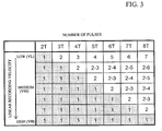
Figure 3 is a table showing how the number of pulses of a pulse
train pattern for modulating the power of a laser beam and linear
recording velocity are related to the length of a recording mark to be
formed using the 1,7RLL Modulation Code.
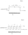
Figure 4 is a set of diagrams showing pulse train patterns used for
recording data in an optical recording medium at a first linear recording
velocity VL, wherein Figure 4 (a) shows a pulse train pattern used for
recording a 2T signal and Figure 4 (b) shows a pulse train pattern used for
recording one of a 3T signal to an 8T signal.
Figure 5 is a set of diagrams showing pulse train patterns used for
recording data in an optical recording medium at a third linear recording
velocity VH, wherein Figure 5 (a) shows a pulse train pattern used for
recording a 2T signal and Figure 5 (b) shows a pulse train pattern used for
recording one of a 3T signal to an 8T signal.
Figure 6 is a set of diagrams showing pulse train patterns used for
recording data in an optical recording medium at a second linear recording
velocity VM higher than a first linear recording velocity VL and lower than
a third linear recording velocity VH, wherein Figure 6 (a) shows a pulse
train pattern used for recording one of a 2T signal to a 5T signal and
Figure 6 (b) shows a pulse train pattern used for recording one of a 6T
signal to an 8T signal.
Figure 7 is a block diagram showing a data recording and
reproducing apparatus that is a preferred embodiment of the present
invention.
Figure 8 is a diagram showing a typical pulse train pattern used for
recording data in a CD-R including a recording layer containing an organic
dye and shows a pulse train pattern for recording one of a 3T signal to an
11T signal in the EFM Modulation Code.
Figure 9 is a diagram showing a typical pulse train pattern (basic
pulse train pattern) used for recording data in a DVD-R including a
recording layer containing an organic dye and shows a pulse train pattern
for recording a 7T signal in the 8/16 Modulation Code.
DESCRIPTION OF THE PREFERRED EMBODIMENTS
Preferred embodiments of the present invention will now be
described with reference to accompanying drawings.
Figure 1 is a schematic cross-sectional view showing the structure
of an optical recording medium that is a preferred embodiment of the
present invention.
As shown in Figure 1, the optical recording medium 10 according to
this embodiment is constituted as a write-once type optical recording
medium and includes a substrate 11, a reflective layer 12 formed on the
surface of the substrate 11, a second dielectric layer 13 formed on the
surface of the reflective layer 12, a second recording layer 32 formed on the
surface of the second dielectric layer 13, a first recording layer 31 formed
on the surface of the second recording layer 32, a first dielectric layer 15
formed on the surface of the first recording layer 31 and a light
transmission layer 16 formed on the surface of the first dielectric layer 15.
As shown in Figure 1, a center hole is formed at a center portion of
the optical recording medium 10.
In this embodiment, as shown in Figure 1, a laser beam L10 is
projected onto the surface of the light transmission layer 16, thereby
recording data in the optical recording medium 10 or reproducing data
from the optical recording medium 10.
The substrate 11 serves as a support for ensuring mechanical
strength required for the optical recording medium 10.
The material used to form the substrate 11 is not particularly
limited insofar as the substrate 11 can serve as the support of the optical
recording medium 10. The substrate 11 can be formed of glass, ceramic,
resin or the like. Among these, resin is preferably used for forming the
substrate 11 since resin can be easily shaped. Illustrative examples of
resins suitable for forming the substrate 40 include polycarbonate resin,
acrylic resin, epoxy resin, polystyrene resin, polyethylene resin,
polypropylene resin, silicone resin, fluoropolymers, acrylonitrile butadiene
styrene resin, urethane resin and the like. Among these, polycarbonate
resin is most preferably used for forming the substrate 11 from the
viewpoint of easy processing, optical characteristics and the like.
In this embodiment, the substrate 11 has a thickness of about 1.1
mm.
The shape of the substrate 11 is not particularly limited but is
normally disk-like, card-like or sheet-like.
As shown in Figure 1, grooves 11a and lands 11b are alternately
formed on the surface of the substrate 11. The grooves 11a and/or lands
11b serve as a guide track for the laser beam L10 when data are to be
recorded or when data are to be reproduced.
The reflective layer 12 serves to reflect the laser beam L10 entering
through the light transmission layer 16 so as to emit it from the light
transmission layer 16.
The thickness of the reflective layer 12 is not particularly limited
but is preferably from 10 nm to 300 nm, more preferably from 20 nm to 200
nm.
The material used to form the reflective layer 12 is not particularly
limited insofar as it can reflect a laser beam, and the reflective layer 12
can be formed of Mg, Al, Ti, Cr, Fe, Co, Ni, Cu, Zn, Ge, Ag, Pt, Au and the
like. Among these materials, it is preferable to form the reflective layer 12
of a metal material having a high reflectivity, such as Al, Au, Ag, Cu or
alloy containing at least one of these metals, such as alloy of Al and Ti.
The reflective layer 12 is provided in order to increase the
difference in reflection coefficient between a recorded region and an
unrecorded region by a multiple interference effect when the laser beam
L10 is used to optically reproduce data from the first recording layer 31
and the second recording layer 32, thereby obtaining a higher reproduced
signal (C/N ratio).
The first dielectric layer 15 and the second dielectric layer 13 serve
to protect the first recording layer 31 and the second recording layer 32.
Degradation of optically recorded data can be prevented over a long period
by the first dielectric layer 15 and the second dielectric layer 13. Further,
since the second dielectric layer 13 also serves to prevent the substrate 11
and the like from being deformed by heat, it is possible to effectively
prevent jitter and the like from becoming worse due to the deformation of
the substrate 11 and the like.
The dielectric material used to form the first dielectric layer 15 and
the second dielectric layer 13 is not particularly limited insofar as it is
transparent and the first dielectric layer 15 and the second dielectric layer
13 can be formed of a dielectric material containing oxide, sulfide, nitride
or a combination thereof, for example, as a primary component. More
specifically, in order to prevent the substrate 11 and the like from being
deformed by heat and thus protect the first recording layer 31 and the
second recording layer 32, it is preferable for the first dielectric layer 15
and the second dielectric layer 13 to contain at least one kind of dielectric
material selected from the group consisting of Al2O3, AlN, ZnO, ZnS, GeN,
GeCrN, CeO, SiO, SiO2, SiN and SiC as a primary component and it is
more preferable for the first dielectric layer 15 and the second dielectric
layer 13 to contain ZnS • SiO2 as a primary component.
The first dielectric layer 15 and the second dielectric layer 13 may
be formed of the same dielectric material or of different dielectric materials.
Moreover, at least one of the first dielectric layer 15 and the second
dielectric layer 13 may have a multi-layered structure including a
plurality of dielectric films.
In this specification, the statement that a dielectric layer contains a
certain dielectric material as a primary component means that the
dielectric material is maximum among dielectric materials contained in
the dielectric layer. ZnS • SiO2 means a mixture of ZnS and SiO2.
The thickness of the first dielectric layer 15 and the second
dielectric layer 13 is not particularly limited but is preferably from 3 nm to
200 nm. If the first dielectric layer 15 or the second dielectric layer 13 is
thinner than 3 nm, it is difficult to obtain the above-described advantages.
On the other hand, if the first dielectric layer 15 or the second dielectric
layer 13 is thicker than 200 nm, it takes a long time to form the first
dielectric layers 15 and the second dielectric layers 13, thereby lowering
the productivity of the optical recording medium 10, and cracks may be
generated in the optical recording medium 10 owing to stress present in
the first dielectric layers 15 and/or the second dielectric layer 13.
The first recording layer 31 and the second recording layer 32 are
adapted for recording data therein. In this embodiment, the first recording
layer 31 is disposed on the side of the light transmission layer 16 and the
second recording layer 32 is disposed on the side of the substrate 11.
In this embodiment, the first recording layer 31 contains an
element selected from the group consisting of Si, Ge, Sn, Mg, In, Zn, Bi and
Al as a primary component and the second recording layer 32 contains Cu
as a primary component.
It is possible to improve the long term storage reliability of an
optical recording medium 10 by proving the first recording layer 31
containing an element selected from the group consisting of Si, Ge, Sn, Mg,
In, Zn, Bi and Al as a primary component and the second recording layer
32 containing Cu as a primary component in this manner.
Further, these elements apply only light load to the environment
and there is no risk of the global atmosphere being damaged.
In order to thoroughly improve the C/N ratio of the reproduced
signal, it is particularly preferable for the first recording layer 31 to
contain an element selected from the group consisting of Ge, Si, Mg, Al and
Sn as a primary component and is particularly preferable for the to contain
Si as a primary component.
Cu contained in the second recording layer 32 as a primary
component quickly mixes with the element contained in the first recording
layer 31 when irradiated with a laser beam L10, thereby enabling data to
be quickly recorded in the first recording layer 31 and the second recording
layer 32.
In order to improve the recording sensitivity of the first recording
layer 31, it is preferable for the first recording layer 31 to be added with at
least one kind of an element selected from the group consisting of Mg, Al,
Cu, Ag and Au.
In order to improve the storage reliability and the recording
sensitivity of the second recording layer 32, it is preferable for the second
recording layer 32 to be added with at least one kind of an element selected
from the group consisting of Al, Si, Zn, Mg, Au, Sn, Ge, Ag, P, Cr, Fe and Ti.
The total thickness of the first recording layer 31 and the second
recording layer 32 is not particularly limited but the surface smoothness of
the first recording layer 31 irradiated with the laser beam L10 becomes
worse as the total thickness of the first recording layer 31 and the second
recording layer 32 becomes thicker. As a result, the noise level of the
reproduced signal becomes higher and the recording sensitivity is lowered.
On the other hand, in the case where the total thickness of the first
recording layer 31 and the second recording layer 32 is too small, the
change in reflection coefficient between before and after irradiation with
the laser beam L10 is small, so that a reproduced signal having high
strength (C/N ratio) cannot be obtained. Moreover, it becomes difficult to
control the thickness of the first recording layer 31 and the second
recording layer 32.
Therefore, in this embodiment, the first recording layer 31 and the
second recording layer 32 are formed so that the total thickness thereof is
from 2 nm to 40 nm. In order to obtain a reproduced signal having higher
strength (C/N ratio) and further decrease the noise level of the reproduced
signal, the total thickness of the first recording layer 31 and the second
recording layer 32 is preferably from 2 nm to 20 nm and more preferably 2
nm to 10 nm.
The individual thicknesses of the first recording layer 31 and the
second recording layer 32 are not particularly limited but in order to
considerably improve the recording sensitivity and greatly increase the
change in reflection coefficient between before and after irradiation with
the laser beam L10, the thickness of the first recording layer 31 is
preferably from 1 nm to 30 nm and the thickness of the second recording
layer 32 is preferably from 1 nm to 30 nm. Further, it is preferable to
define the ratio of the thickness of the first recording layer 31 to the
thickness of the second recording layer 32 (thickness of first recording
layer 31 / thickness of second recording layer 32) to be from 0.2 to 5.0.
The light transmission layer 16 serves to transmit a laser beam L10
and preferably has a thickness of 10 µm to 300 µm. More preferably, the
light transmission layer 16 has a thickness of 50 µm to 150 µm.
The material used to form the light transmission layer 16 is not
particularly limited but in the case where the light transmission layer 16
is to be formed by the spin coating process or the like, ultraviolet ray
curable resin, electron beam curable resin or the like is preferably used.
More preferably, the light transmission layer 16 is formed of ultraviolet
ray curable resin.
The light transmission layer 16 may be formed by adhering a sheet
made of light transmittable resin to the surface of the first dielectric layer
15 using an adhesive agent.
The optical recording medium 10 having the above-described
configuration can, for example, be fabricated in the following manner.
The reflective layer 12 is first formed on the surface of the substrate
11 formed with the grooves 11a and lands 11b.
The reflective layer 12 can be formed by a gas phase growth process
using chemical species containing elements for forming the reflective layer
12. Illustrative examples of the gas phase growth processes include
vacuum deposition process, sputtering process and the like.
The second dielectric layer 13 is then formed on surface of the
reflective layer 12.
The second dielectric layer 13 can be also formed by a gas phase
growth process using chemical species containing elements for forming the
second dielectric layer 13. Illustrative examples of the gas phase growth
processes include vacuum deposition process, sputtering process and the
like.
The second recording layer 32 is further formed on the second
dielectric layer 13. The second recording layer 32 can be also formed by a
gas phase growth process using chemical species containing elements for
forming the second recording layer 32.
The first recording layer 31 is then formed on the second recording
layer 32. The first recording layer 31 can be also formed by a gas phase
growth process using chemical species containing elements for forming the
first recording layer 31.
The first dielectric layer 15 is then formed on the first recording
layer 31. The first dielectric layer 15 can be also formed by a gas phase
growth process using chemical species containing elements for forming the
first dielectric layer 15.
Finally, the light transmission layer 16 is formed on the first
dielectric layer 15. The light transmission layer 16 can be formed, for
example, by applying an acrylic ultraviolet ray curable resin or epoxy
ultraviolet ray curable resin adjusted to an appropriate viscosity onto the
surface of the second dielectric layer 15 by spin coating to form a coating
layer and irradiating the coating layer with ultraviolet rays to cure the
coating layer.
Thus, the optical recording medium 10 was fabricated.
Data are recorded in the optical recording medium 10 of the above-described
configuration, in the following manner, for example.
As shown in Figure 1 and 2 (a), the first recording layer 31 and the
second recording layer 32 are first irradiated via the light transmission
layer 16 with a laser beam L10 having predetermined power.
In order to record data with high recording density, it is preferable
to project a laser beam L10 having a wavelength λ of 450 nm or shorter
onto the optical recording medium 10 via an objective lens (not shown)
having a numerical aperture NA of 0.7 or more and it is more preferable
that λ/NA be equal to or smaller than 640 nm. In such a case, the spot
diameter of the laser beam L10 on the surface of the first recording layer
31 becomes equal to or smaller than 0.65 µm.
In this embodiment, a laser beam L10 having a wavelength λ of 405
nm is condensed onto the optical recording medium 10 via an objective lens
having a numerical aperture NA of 0.85 so that the spot diameter of the
laser beam L10 on the surface of the first recording layer 31 becomes about
0.43 µm.
As a result, the element contained in the first recording layer 31 as
a primary component and the element contained in the second recording
layer 32 as a primary component mix with each other and as shown in
Figure 2(b), a recording mark M composed of a mixture of the primary
component element of the first recording layer 31 and the primary
component element of the second recording layer 32 is formed.
When the primary component elements of the first recording layers
31 and 32 are mixed, the reflection coefficient of the region markedly
changes. Since the reflection coefficient of the thus formed recording mark
M is therefore greatly different from that of the region surrounding the
mixed region M, it is possible to obtain a high reproduced signal (C/N
ratio) when optically recorded information is reproduced.
When the laser beam L10 is projected, the first recording layer 31
and the second recording layer 32 are heated by the laser beam L10. In
this embodiment, however, the first dielectric layer 15 and the second
dielectric layer 13 are disposed outward of the first recording layer 31 and
the second recording layer 32. Deformation of the substrate 11 and the
light transmission layer 16 by heat is therefore effectively prevented.
In the case where data are to be recorded in an optical recording
medium 10 by projecting a laser beam L10 thereonto, the power of the
laser beam L10 is modulated in accordance with a pulse train pattern
including pulses whose levels are set to a recording power Pw and a bottom
power Pb.
In a next-generation type optical recording medium 10 shown in
Figures 1 and 2, it is required to record data at a high linear recording
velocity and in a write-once type optical recording medium, a recording
power Pw necessary for forming a recording mark is substantially
proportional to the square root of the linear recording velocity. Therefore,
it is necessary to set the recording power Pw of a pulse train pattern to a
high level in order to record data in the optical recording medium 10 at a
high linear recording velocity.
However, since the output of a semiconductor laser adapted for
emitting a laser beam having a wavelength equal to or shorter than 450
nm and used for recording data in the next-generation type optical
recording medium 10 is low and a semiconductor laser having a high
output is expensive, even in the case where data are to be recorded in the
optical recording medium 10 at a high linear recording velocity, it is
necessary to select a pulse train pattern that enables data to be recorded
therein at the lowest linear recording velocity possible.
In a study done by the inventors of the present invention, it was
found that it was effective to increase the total amount of heat supplied for
forming a recording mark M by modulating the power of the laser beam
L10 using the single pulse pattern in order to record data in the optical
recording medium 10 at a high linear recording velocity using a laser beam
having a low recording power but that in the case where the linear
recording velocity of data was low, if a recording mark was formed by
modulating the power of the laser beam L10 using a single pulse pattern,
the total amount of heat supplied for forming a recording mark became
excessive and the recording mark became wider, whereby cross-talk of
data increased. It was further found that this tendency became
pronounced as the length of the recording mark became longer.
Therefore, in this embodiment, a pulse train pattern having a
smaller number of pulses whose level is set to a level corresponding to a
recording power Pw is employed as the linear recording velocity of data is
higher, thereby modulating the power of a laser beam L10 to form a
recording mark.
Concretely, in the case of employing the 1,7RLL Modulating Code,
as shown in Figure 3, the number of pulses of the pulse train pattern is
selected in accordance with the linear recording velocity and the length of
the recording mark M to be formed.
More specifically, as shown in Figure 3, in the case where data are
to be recorded in the optical recording medium 10 at a first linear
recording velocity VL which is low, the basic pulse train pattern is selected
as the pulse train pattern for modulating the power of the laser beam L10
and when an nT signal is to be recorded where n is an integer of 2 to 8 in
the 1,7RLL Modulation Code, the basic pulse train pattern including (n -
1) divided pulses is employed. In the case where a 2T signal is to be
recorded, the number of the divided pulses becomes 1 and the basic pulse
train pattern has the same pattern as that of the single pulse pattern.
To the contrary, in the case where data are to be recorded in the
optical recording medium 10 at a third linear recording velocity VH which
is high, the single pulse pattern is selected as the pulse train pattern for
modulating the power of the laser beam L10. Here, the first linear
recording velocity VL and the third linear recording velocity VH preferably
are such that 2*VL is equal to or lower than VH and more preferably are
such that 4*VL is equal to or lower than VH. Further, the third linear
recording velocity VH is preferably equal to or higher than 10 m/sec and
more preferably is equal to or higher than 20 m/sec.
On the other hand, in the case where data are to be recorded in the
optical recording medium 10 at a second linear recording velocity VM
higher than the first linear recording velocity VL and lower than the third
linear recording velocity VH, the single pulse pattern is selected as the
pulse train pattern for modulating the power of the laser beam L10 when
the recording mark M to be formed is short, while the basic pulse train
pattern is selected as the pulse train pattern for modulating the power of
the laser beam L10 when the recording mark M to be formed is long.
Further, in the case where a recording mark M having the same
length is to be formed in the optical recording medium 10 at a second
linear recording velocity VM higher than the first linear recording velocity
VL and lower than the third linear recording velocity VH, the pulse train
pattern is determined so that the number of pulses included in the pulse
train pattern is larger as the linear recording velocity VM becomes lower
and on the other hand, when the linear recording velocity VM is the same
in the case where a recording mark M having the same length is to be
formed in the optical recording medium 10 at a second linear recording
velocity VM higher than the first linear recording velocity VL and lower
than the third linear recording velocity VH, the pulse train pattern is
determined so that the number of pulses included in the pulse train
pattern is larger as the recording mark becomes longer.
In this embodiment, the basic pulse train pattern includes not only
the basic pulse train pattern shown in Figure 9 and including (n - 1)
divided pulses but also a basic pulse train pattern including n or (n - 2)
divided pulses. It is preferable to employ a basic pulse train pattern
including (n - 2) divided pulses in the 8/16 Modulation Code and employ a
pulse train pattern including (n - 1) divided pulses in the 1,7RLL
Modulation Code.
Figure 4 is a set of diagrams showing pulse train patterns used for
recording data in an optical recording medium at the first linear recording
velocity VL, wherein Figure 4 (a) shows a pulse train pattern used for
recording a 2T signal and Figure 4 (b) shows a pulse train pattern used for
recording one of a 3T signal to an 8T signal.
As shown in Figure 4 (a) and Figure 4 (b), in the case where data
are to be recorded in the optical recording medium 10 at the first linear
recording velocity VL, the recording pulse for forming a recording mark M
is divided into (n - 1) divided pulses and the power of the laser beam L10 is
set to a recording power PwL at the peak of each of the divided pulses and
set to a bottom power PbL at the other portions of the pulse.
In this manner, in the case where data are to be recorded in the
optical recording medium 10 at the first linear recording velocity VL, since
the recording pulse for forming the recording mark M is divided into (n - 1)
divided pulses and the power of the laser beam L10 is set to a recording
power PwL at the peak of each of the divided pulses and set to a bottom
power PbL at the other portions of the pulse, it is possible to prevent a
total amount of heat supplied for forming the recording mark M from
becoming excessive and it is therefore possible to effectively prevent the
recording mark from becoming wider and cross-talk of data from
increasing.
The recording power PwL is set to a high level at which the element
contained in the first recording layer 31 as a primary component and the
element contained in the second recording layer 32 as a primary
component can be heated and mixed to form a record mark M when a laser
beam having the recording power PwL is projected onto the optical
recording medium 10. On the other hand, the first bottom power PbL is set
to a low level at which the element contained in the first recording layer 31
as a primary component and the element contained in the second recording
layer 32 as a primary component cannot substantially be mixed even when
a laser beam having the first bottom power PbL is projected onto the
optical recording medium 10.
Further, as shown in Figure 4 (a) and Figure 4 (b), the bottom
power PbL is set to a level higher than a reproducing power Pr.
If the level of the bottom power PbL is set to a higher level than the
reproducing power Pr in this manner, it is possible to augment the heating
of the recording layer by the laser beam L10 having the recording power
PwL by the laser beam L10 having the bottom power PbL and the
recording power PwL can be therefore set to a low level.
Figure 5 is a set of diagrams showing pulse train patterns used for
recording data in the optical recording medium 10 at the third linear
recording velocity VH, wherein Figure 5 (a) shows a pulse train pattern
used for recording a 2T signal and Figure 5 (b) shows a pulse train pattern
used for recording one of a 3T signal to an 8T signal.
As shown in Figure 5 (a) and Figure 5 (b), in the case where data
are to be recorded in the optical recording medium 10 at the third linear
recording velocity VH, the single pulse train pattern is selected as a pulse
train pattern for modulating the power of the laser beam L10 and the
power of the laser beam L10 is set to a recording layer PwH at regions
where recording marks M are to be formed and set to a bottom power PbH
at other portions of the pulse.
Therefore, since the total amount of heat supplied for forming a
recording mark M can be increased, it is possible to set the recording layer
PwH to a low level.
The recording power PwH is set to a high level at which the element
contained in the first recording layer 31 as a primary component and the
element contained in the second recording layer 32 as a primary
component can be heated and mixed to form a record mark M when a laser
beam having the recording power PwH is projected onto the optical
recording medium 10. On the other hand, the first bottom power PbH is set
to a low level at which the element contained in the first recording layer 31
as a primary component and the element contained in the second recording
layer 32 as a primary component cannot substantially be mixed even when
a laser beam having the first bottom power PbH is projected onto the
optical recording medium 10.
The bottom power PbH is set to a level higher than a reproducing
power Pr. If the level of the bottom power PbH is set to a higher level than
the reproducing power Pr in this manner, it is possible to augment the
heating of the recording layer by the laser beam L10 having the recording
power PwH by the laser beam L10 having the bottom power PbH and the
recording power PwH can be therefore set to a low level.
Figure 6 is a set of diagrams showing pulse train patterns used for
recording data in the optical recording medium 10 at the second linear
recording velocity VM higher than the first linear recording velocity VL
and lower than the third linear recording velocity VH, wherein Figure 6 (a)
shows a pulse train pattern used for recording one of a 2T signal to a 5T
signal and Figure 6 (b) shows a pulse train pattern used for recording one
of a 6T signal to an 8T signal.
As shown in Figure 6 (a), in the case where data are to be recorded
in the optical recording medium 10 at the second linear recording velocity
VM lower than the third linear recording velocity VH, the single pulse
pattern is selected as a pulse train pattern for modulating the power of the
laser beam L10 when one of a 2T signal to a 5T signal is to be recorded and
the basic pulse train pattern including 2 to 4 divided pulses is selected
when one of a 6T signal to an 8T signal is to be recorded. In these cases,
the power of the laser beam L10 is modulated so as to be equal to a
recording power PwM at the peak of the single pulse or each of the divided
pulses and equal to a bottom power PbM at other portions of the pulse.
If a pulse train pattern for modulating the power of the laser beam
L10 is determined in this manner, when one of a 2T signal to a 5T signal is
to be recorded, since the total amount of heat supplied for forming a
recording mark M becomes large, it is possible to set the recording power
PwM to a low level. On the other hand, since it is possible to prevent the
total amount of heat supplied for forming a recording mark M from
becoming excessive, it is possible to effectively prevent a long recording
mark M formed using one of a 6T signal to an 8T signal from becoming
wider and cross-talk of data from increasing.
The recording power PwM is set to a high level at which the
element contained in the first recording layer 31 as a primary component
and the element contained in the second recording layer 32 as a primary
component can be heated and mixed to form a record mark M when a laser
beam having the recording power PwM is projected onto the optical
recording medium 10. On the other hand, the first bottom power PbM is
set to a low level at which the element contained in the first recording
layer 31 as a primary component and the element contained in the second
recording layer 32 as a primary component cannot substantially be mixed
even when a laser beam having the first bottom power PbM is projected
onto the optical recording medium 10.
The bottom power PbM is set to a level higher than a reproducing
power Pr. If the level of the bottom power PbM is set to a higher level than
the reproducing power Pr in this manner, it is possible to augment the
heating of the recording layer by the laser beam L10 having the recording
power PwM by the laser beam L10 having the bottom power PbM and the
recording power PwM can be therefore set to a low level.
It is preferable for the bottom power PbL of the pulse train pattern
used for recording data at the first linear recording velocity VL, the bottom
power PbH of the pulse train pattern used for recording data at the third
linear recording velocity VH and the bottom power PbM of the pulse train
pattern used for recording data at the second linear recording velocity VM
to be such that PbL is lower than PbM and PbM is equal to or lower than
PbH, more preferable for them to be such that 3*PbL is equal to or lower
than PbM and PbM is equal to or lower than PbH and most preferable for
them to be such that 5*PbL is equal to or lower than PbM and PbM is
lower than PbH.
Further, it is preferable to determine the pulse train patterns so
that a ratio (PbL / PwL) of the bottom power PbL to the recording power
PwL of the pulse train pattern used for recording data at the first linear
recording velocity VL, a ratio (PbH / PwH) of the bottom power PbH to the
recording power PwH of the pulse train pattern used for recording data at
the third linear recording velocity VH and a ratio (PbM / PwM) of the
bottom power PbM to the recording power PwM of the pulse train pattern
used for recording data at the second linear recording velocity VM are such
that (PbL / PwL) is lower than (PbM / PwM) and (PbM / PwM) is equal to
or lower than (PbH / PwH) and it is more preferable for the ratios to be
such that 3*(PbL / PwL) is equal to or lower than (PbM / PwM) and (PbM /
PwM) is equal to or lower than (PbH / PwH) and most preferable for the
ratios to be such that 5*(PbL / PwL) is equal to or lower than (PbM / PwM)
and (PbM / PwM) is equal to or lower than (PbH / PwH).
In the case where the recording powers and the bottom powers of
the pulse train patterns used for modulating the power of a laser beam are
set in this manner, when data are to be recorded at different linear
recording velocities in a (multi-velocity recording) system in which data
can be recorded by selecting a desired linear recording velocity selected
from among a plurality of linear recording velocities, it is possible to set
the recording powers to substantially the same level.
Therefore, in this embodiment, since it is possible to set the
recording power PwM to a low level and set recording powers to
substantially the same level in the case of recording data at different
linear recording velocities, it is possible to employ a relatively inexpensive
semiconductor laser having a low output.
According to this embodiment, since the single pulse pattern is
selected as the pulse train pattern for modulating the power of the laser
beam L10 in the case where data are to be recorded at the third linear
recording velocity VH, which is high, it is possible to increase the total
amount of heat supplied for forming a recording mark M and it is therefore
possible to record data in the optical recording medium 10 with the
recording power PwH set to a lower level.
Further, according to this embodiment, in the case where data are
to be recorded at the first linear recording velocity VL, which is low, since
the basic pulse train pattern is selected as the pulse train pattern for
modulating the power of a laser beam L10 and the basic pulse train
pattern including (n - 1) divided pulses when an nT signal is to be recorded
where n is an integer of 2 to 8 in the (1,7)RLL Modulation Code, it is
possible to effectively prevent the total amount of heat supplied for
forming a recording mark M from increasing excessively, whereby it is
possible to prevent widening of the width of the recording mark M and
increase in cross-talk of data.
Therefore, according to this embodiment, even in the case where
data are to be recorded in an optical recording medium 10 at a high linear
recording velocity, it is possible to employ a relatively inexpensive
semiconductor laser having a low output.
Figure 7 is a block diagram showing a data recording apparatus
that is a preferred embodiment of the present invention.
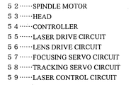
As shown in Figure 7, a data recording apparatus 100 includes a
spindle motor 52 for rotating the optical recording medium 10, a head 53
for projecting a laser beam onto the optical recording medium 10 and
receiving the light reflected by the optical recording medium 10, a
controller 54 for controlling the operation of the spindle motor 52 and the
head 53, a laser drive circuit 55 for feeding a laser drive signal to the head
53, and a lens drive circuit 56 for feeding a lens drive signal to the optical
head 53.
As shown in Figure 7, the controller 54 includes a focus servo
tracking circuit 57, a tracking servo circuit 58 and a laser control circuit
59.
When the focus servo tracking circuit 57 is activated, a laser beam
L10 is focused onto the first recording layer 51 of the rotating optical
recording medium 10 and when the tracking servo circuit 58 is activated,
the spot of the laser beam L10 automatically follows the track of the
optical recording medium 10.
As shown in Figure 7, each of the focus servo tracking circuit 57 and
the tracking servo circuit 58 has an auto-gain control function for
automatically adjusting the focus gain and an auto-gain control function
for automatically adjusting the tracking gain. Further, the laser control
circuit 59 is adapted to generate a laser drive signal to be supplied by the
laser drive circuit 55.
In this embodiment, data for identifying the above described pulse
train patterns are recorded in the optical recording medium 10 together
with data for identifying various recording conditions, such as a linear
recording velocity necessary for recording data, as data for setting
recording conditions in the form of wobbles or pre-pits.
Therefore, the laser control circuit 59 reads data for setting
recording conditions recorded in the optical recording medium 10 prior to
recording data in the optical recording medium 10, selects the desired
pulse train pattern based on the thus read data for setting recording
conditions to generate a laser drive signal and causes the laser drive
circuit 55 to output it to the head 53.
Thus, data are recorded in the optical recording medium 10 in
accordance with the desired recording strategy.
According to this embodiment, the optical recording medium 10 is
recorded with data for identifying the pulse train patterns together with
data for identifying various recording conditions, such as a linear
recording velocity necessary for recording data, as data for setting
recording conditions and prior to recording data in the optical recording
medium 10, the laser control circuit 59 reads data for setting recording
conditions recorded in the optical recording medium 10, selects the desired
pulse train pattern based on the thus read data for setting recording
conditions to generate a laser drive signal and control the head 53 for
projecting a laser beam onto the optical recording medium 10. Therefore, it
is possible to record data in accordance with the desired recording strategy.
WORKING EXAMPLES AND A COMPARATIVE EXAMPLE
Hereinafter, working examples and a comparative example will be
set out in order to further clarify the advantages of the present invention.
Working Example 1
An optical recording medium having the same configuration as that
of the optical recording medium 1 shown in Figure 1 was fabricated in the
following manner.
A polycarbonate substrate having a thickness of 1.1 mm and a
diameter of 120 mm was first set on a sputtering apparatus. Then, a
reflective layer containing a mixture of Ag, Pd and Cu and having a
thickness of 100 nm, a second dielectric layer containing a mixture of ZnS
and SiO2 and having a thickness of 30 nm, a second recording layer
containing Cu as a primary component and having a thickness of 5 nm, a
first recording layer containing Si as a primary component and having a
thickness of 5 nm and a first dielectric layer containing the mixture of ZnS
and SiO2 and having a thickness of 25 nm were sequentially formed on the
polycarbonate substrate using the sputtering process.
The mole ratio of ZnS to SiO2 in the mixture of ZnS and SiO2
contained in the first dielectric layer and the second dielectric layer was
80:20.
Further, the first dielectric layer was coated using the spin coating
method with an acrylic ultraviolet ray curable resin to form a coating layer
and the coating layer was irradiated with ultraviolet rays, thereby curing
the acrylic ultraviolet ray curable resin to form a light transmission layer
having a thickness of 100 µm.
The thus fabricated optical recording medium was set in an optical
recording medium evaluation apparatus "DDU1000" (Product Name)
manufactured by Pulstec Industrial Co., Ltd. Then, a blue laser beam
having a wavelength of 405 nm was employed as the laser beam for
recording data and the laser beam was condensed onto the optical
recording medium via the light transmission layer using an objective lens
whose numerical aperture was 0.85, and data were recorded therein.
As a record signal, a random signal including a 2T signal to an 8T
signal in no particular order was used and the power of a laser beam was
modulated using the first pulse train pattern including (n - 1) divided
pulses irrespective of the recording signal
Data were recorded by fixing the bottom power Pb of the first pulse
train pattern to 0.5 mW and varying the recording power Pw between the
first linear recording velocity VL, the second linear recording velocity VM
and the third linear recording velocity VH.
The first linear recording velocity VL was set to 5.3 m/sec (channel
clock: 66 MHz), the second linear recording velocity VM was set to 10.6
m/sec (channel clock: 132 MHz) and the third linear recording velocity VH
was set to 21.2 m/sec (channel clock: 263 MHz).
At the first linear recording velocity VL, when the format efficiency
was 80%, the data transfer rate was about 35 Mbps and the ratio of the
shortest blank region interval to the linear recording velocity (shortest
blank region interval / linear recording velocity) was 30.4 nsec. Further, at
the second linear recording velocity VM, when the format efficiency was
80%, the data transfer rate was about 70 Mbps and the ratio of the
shortest blank region interval to the linear recording velocity (shortest
blank region interval / linear recording velocity) was 15.2 nsec. Moreover,
at the third linear recording velocity VH, when the format efficiency was
80%, the data transfer rate was about 140 Mbps and the ratio of the
shortest blank region interval to the linear recording velocity (shortest
blank region interval / linear recording velocity) was 7.6 nsec.
Then, data recorded in the optical recording medium were
reproduced using the above mentioned optical recording medium
evaluation apparatus and the recording power Pw of the laser beam at
which clock jitter of the reproduced signal was minimum was measured
and determined as the optical recording power. When data were to be
reproduced, a laser beam having a wavelength of 405 nm and an objective
lens having a numerical aperture NA of 0.85 were employed. The
fluctuation σ of the reproduced signal was measured using a time interval
analyzer and the clock jitter was calculated as σ/Tw, where Tw was one
clock period.
The results of the measurement are shown in Table 1.
Working Example 2
Data were recorded in the optical recording medium in the manner
of Working Example 1 except that the power of the laser beam was
modulated using the second pulse train pattern constituted so that the
single pulse pattern was selected when one of a 2T signal to a 5T signal
was recorded and the basic pulse train pattern including two to four
divided pulses was selected when one of a 6T signal to an 8T signal was
recorded. Then, data recorded in the optical recording medium were
reproduced and the recording power Pw of the laser beam at which clock
jitter of the reproduced signal was minimum was measured and
determined as the optical recording power.
The results of the measurement are shown in Table 1.
Working Example 3
Data were recorded in the optical recording medium in the manner
of Working Example 1 except that the power of the laser beam was
modulated using the third pulse train pattern constituted so that the
single pulse pattern was selected irrespective of the recording signal. Then,
data recorded in the optical recording medium were reproduced and the
recording power Pw of the laser beam at which clock jitter of the
reproduced signal was minimum was measured and determined as the
optical recording power.
The results of the measurement are shown in Table 1.
| | Pb=0.5mW |
| | First linear recording velocity (VL) | Second linear recording velocity (VM) | Third linear recording velocity (VH) |
| First pulse train pattern | 4.5mW | 6.3mW | - |
| Second pulse train pattern | 3.5mW | 4.7mW | 6.5mW |
| Third pulse train patter | 3.1mW | 4.1mW | 5.3mW |
As shown in Table 1, it was found that in the case where the bottom
power Pb was fixed at 0.5 mW, the optimum recording power became
higher as the linear recording velocity increased.
Further, it was found that at each linear recording velocity, the
optical recording powers became lower in the order of the first pulse train
pattern, the second pulse train pattern and the third pulse train pattern.
However, since the rate of laser beam power modulation was
restricted in the optical recording medium evaluation apparatus used for
the experiments, data could not be recorded in the optical recording
medium at the third linear recording velocity VH by modulating the power
of the laser beam in accordance with the third pulse train pattern.
Working Example 4
Data were recorded in the optical recording medium in the manner
of Working Example 1 except that the bottom power Pb of the first pulse
train pattern was set to 1.5 mW when data were to be recorded in the
optical recording medium at the first linear recording velocity VL, that the
bottom power Pb of the first pulse train pattern was set to 2.0 mW when
data were to be recorded in the optical recording medium at the second
linear recording velocity VM and that the bottom power Pb of the first
pulse train pattern was set to 2.5 mW when data were to be recorded in the
optical recording medium at the third linear recording velocity VH. Then,
data recorded in the optical recording medium were reproduced and the
recording power Pw of the laser beam at which clock jitter of the
reproduced signal was minimum was measured and determined as the
optical recording power.
The results of the measurement are shown in Table 2.
In Table 2, each value in parentheses indicates the difference
between the optical recording power obtained in this Working Example
and that obtained in Working Example 1.
Working Example 5
Data were recorded in the optical recording medium in the manner
of Working Example 1 except that the bottom power Pb of the second pulse
train pattern was set to 1.5 mW when data were to be recorded in the
optical recording medium at the first linear recording velocity VL, that the
bottom power Pb of the second pulse train pattern was set to 2.0 mW when
data were to be recorded in the optical recording medium at the second
linear recording velocity VM and that the bottom power Pb of the second
pulse train pattern was set to 2.5 mW when data were to be recorded in the
optical recording medium at the third linear recording velocity VH. Then,
data recorded in the optical recording medium were reproduced and the
recording power Pw of the laser beam at which clock jitter of the
reproduced signal was minimum was measured and determined as the
optical recording power.
The results of the measurement are shown in Table 2.
In Table 2, each value in parentheses indicates the difference
between the optical recording power obtained in this Working Example
and that obtained in Working Example 2.
Working Example 6
Data were recorded in the optical recording medium in the manner
of Working Example 1 except that the bottom power Pb of the third pulse
train pattern was set to 1.5 mW when data were to be recorded in the
optical recording medium at the first linear recording velocity VL, that the
bottom power Pb of the third pulse train pattern was set to 2.0 mW when
data were to be recorded in the optical recording medium at the second
linear recording velocity VM and that the bottom power Pb of the third
pulse train pattern was set to 2.5 mW when data were to be recorded in the
optical recording medium at the third linear recording velocity VH. Then,
data recorded in the optical recording medium were reproduced and the
recording power Pw of the laser beam at which clock jitter of the
reproduced signal was minimum was measured and determined as the
optical recording power.
The results of the measurement are shown in Table 2.
In Table 2, each value in parentheses indicates the difference
between the optical recording power obtained in this Working example and
that obtained in Working Example 3.
| | Pb=1.5mW | Pb=2.0mW | Pb=2.5mW |
| | First linear recording velocity (VL) | Second linear recording velocity (VM) | Third linear recording velocity (VH) |
| First pulse train pattern | 4.2mW (-0.3) | 4.8mW (-1.5) | - |
| Second pulse train pattern | 3.3mW (-0.2) | 3.9mW (-0.8) | 5.2mW (-1.3) |
| Third pulse train patter | 3.0mW (-0.1) | 3.4mW (-0.7) | 4.3mW (-1.0) |
As shown in Table 2, it was found that in the case where the bottom
power Pb of each of the pulse train patterns was set to 1.5 mW when data
were to be recorded in the optical recording medium at the first linear
recording velocity VL, the bottom power Pb of each of the pulse train
patterns was set to 2.0 mW when data were to be recorded in the optical
recording medium at the second linear recording velocity VM and that the
bottom power Pb of each of the pulse train patterns was set to 2.5 mW
when data were to be recorded in the optical recording medium at the third
linear recording velocity VH, the optimum recording power Pw decreased
in comparison of the case of setting the bottom power Pb of each of the
pulse train patterns to 0.5 mW.
Further, it was found that the reduction in the optimum recording
power Pw became larger as the linear recording velocity increased. It is
reasonable to assume that the reason for this finding is as follows.
Specifically, since the influence of heat transmitted from neighboring
recording marks becomes great as the linear recording velocity increases,
the reduction in the optimum recording power Pw caused by setting the
bottom power Pb of each of the pulse train patterns to a high level becomes
great as the linear recording velocity increases.
Working Example 7
The recording power Pw was set to the optimum recording power
obtained in Working Example 4 and a random signal including a 2T signal
to an 8T signal in no particular order was recorded on one track of the
optical recording medium in the manner of Working Example 4. Then, the
thus recorded signal was reproduced and clock jitter of the reproduced
signal was measured. Hereinafter, the thus measured clock jitter is
referred to as "single jitter."
Further, a random signal including a 2T signal to an 8T signal in no
particular order was recorded on three tracks adjacent to each other under
the same recording conditions. Then, the signal recorded in the central
track was reproduced and clock jitter of the reproduced signal was
measured. Hereinafter, the thus measured clock jitter is referred to as
"cross jitter."
Further, the difference between the single jitter and the cross jitter
was determined for each of the linear recording velocities.
The results of the determination are shown in Table 3.
Working Example 8
The recording power Pw was set to the optimum recording power
obtained in Working Example 5 and a random signal including a 2T signal
to an 8T signal in no particular order was recorded on one track of the
optical recording medium in the manner of Working Example 5. Then, the
thus recorded signal was reproduced and single jitter of the reproduced
signal was measured.
Further, a random signal including a 2T signal to an 8T signal in no
particular order was recorded on three tracks adjacent with each other
under the same recording conditions. Then, the signal recorded in the
central track was reproduced and cross jitter of a reproduced signal was
measured.
Further, a difference between the single jitter and the cross jitter
was determined for each of the linear recording velocities.
The results of the determination are shown in Table 3.
Working Example 9
The recording power Pw was set to the optimum recording power
obtained in Working Example 6 and a random signal including a 2T signal
to an 8T signal in no particular order was recorded on one track of the
optical recording medium in the manner of Working Example 6. Then, the
thus recorded signal was reproduced and single jitter of the reproduced
signal was measured.
Further, a random signal including a 2T signal to an 8T signal in no
particular order was recorded on three tracks adjacent with each other
under the same recording conditions. Then, the signal recorded in the
central track was reproduced and cross jitter of the reproduced signal was
measured.
Further, the difference between the single jitter and the cross jitter
was determined for each of the linear recording velocities.
The results of the determination are shown in Table 3.
| | First linear recording velocity (VL) | Second linear recording velocity (VM) | Third linear recording velocity (VH) |
| First pulse train pattern | 0.5% | 0.4% | - |
| Second pulse train pattern | 0.7% | 0.5% | 0.5% |
| Third pulse train patter | 1.0% | 0.8% | 0.5% |
As shown in Table 3, it was found that in the case where data were
recorded in the optical recording medium at each of the first linear
recording velocity VL and the second linear recording velocity VM, the
difference between single jitter and cross jitter became larger and cross-talk
of data increased in the order of the first pulse train pattern, the
second pulse train pattern and the third pulse train pattern. It is
reasonable to assume that this was because the width of the recording
mark became larger in the order of the first pulse train pattern, the second
pulse train pattern and the third pulse train pattern.
Further, it was found that the increase in the difference between
single jitter and cross jitter in the order of the first pulse train pattern, the
second pulse train pattern and the third pulse train pattern was larger in
the case of recording data at the first linear recording velocity VL than
that in the case of recording data at the second linear recording velocity
VM.
On the other hand, it was found that in the case where data were
recorded at the third linear recording velocity VH, there was no significant
difference between the difference between single jitter and cross jitter
obtained when the second pulse train pattern was employed and that
obtained when the third pulse train pattern was employed.
From Working Example 1 to Working Example 9, it was found that
since in the case of recording data in the optical recording medium at the
first linear recording velocity VL crosstalk of data increased when the
power of a laser beam was modulated using the second pulse train pattern
or the third pulse train pattern, it was preferable to modulate the power of
a laser beam using the first pulse train pattern in the case of recording
data in the optical recording medium at the first linear recording velocity
VL. It is reasonable to conclude that the reason for this finding is as
follows. Specifically, in the case of recording data in the optical recording
medium at the first linear recording velocity VL, since the linear recording
velocity is low, it is not basically required to increase the level of a
recording power Pw. As a consequence, if the level of the recording power
Pw is increased, cross-talk of data increases.
Further, from Working Example 1 to Working Example 9, it was
found that although in the case of recording data in the optical recording
medium at the second linear recording velocity VM, cross-talk of data
became larger in the order of the first pulse train pattern, the second pulse
train pattern and the third pulse train pattern, it was more important to
reduce the level of the recording power Pw in the case of recording data in
the optical recording medium at the second linear recording velocity VM
and it was therefore preferable to modulate the power of the laser beam
using the second pulse train pattern.
Furthermore, from Working Example 1 to Working Example 9, it
was found that in the case of recording data in the optical recording
medium at the third linear recording velocity VH, since it was possible to
set the level of the recording power Pw to the lowest level when the power
of the laser beam was modulated using the third pulse train pattern and
there was no significant difference in the level of cross-talk of data
between when the power of the laser beam was modulated using the third
pulse train pattern and when it was modulated by the second pulse train
pattern, it was preferable to modulate the power of the laser beam using
the third pulse train pattern in the case of recording data in the optical
recording medium at the third linear recording velocity VH.
The present invention has thus been shown and described with
reference to a specific embodiment and Working Examples. However, it
should be noted that the present invention is in no way limited to the
details of the described arrangements but changes and modifications may
be made without departing from the scope of the appended claims.
For example, in the above described embodiment and Working
Examples, although the first recording layer 31 and the second recording
layer 32 are formed in contact with each other, it is not absolutely
necessary to form the first recording layer 31 and the second recording
layer 32 in contact with each other but it is sufficient for the second
recording layer 32 to be so located in the vicinity of the first recording layer
31 as to enable formation of a mixed region including the primary
component element of the first recording layer 31 and the primary
component element of the second recording layer 32 when the region is
irradiated with a laser beam. Further, one or more other layers such as a
dielectric layer may be interposed between the first recording layer 31 and
the second recording layer 32.
Further, in the above described embodiment, although the first
recording layer 31 contains an element selected from the group consisting
of Si, Ge, Sn, Mg, In, Zn, Bi and Al as a primary component and the second
recording layer 32 contains Cu as a primary component, it is not absolutely
necessary for the first recording layer 31 to contain an element selected
from the group consisting of Si, Ge, Sn, Mg, In, Zn, Bi and Al as a primary
component and for the second recording layer 32 to contain Cu as a
primary component and the first recording layer 31 may contain an
element selected from the group consisting of Si, Ge, C, Sn, Zn and Cu as a
primary component and the second recording layer 32 may contain Al as a
primary component. Further, the first recording layer 31 may contain an
element selected from the group consisting of Si, Ge, C and Al as a primary
component and the second recording layer 32 may contain Zn as a primary
component. Moreover, it is sufficient for the first recording layer 31 and
the second recording layer 32 to contain different elements from each other
and contain an element selected from the group consisting of Al, Si, Ge, C,
Sn, Au, Zn, Cu, B, Mg, Ti, Mn, Fe, Ga, Zr, Ag and Pt as a primary
component.
Furthermore, in the above described embodiment and Working
Examples, although the optical recording medium 10 includes the first
recording layer 31 and the second recording layer 32, the optical recording
medium may include one or more recording layers containing an element
selected from the group consisting of Si, Ge, Sn, Mg, In, Zn, Bi and Al as a
primary component or one or more recording layers containing Al as a
primary element, in addition to the first recording layer 31 and the second
recording layer 32.
Moreover, although the first recording layer 31 is disposed on the
side of the light transmission layer 16 and the second recording layer 32 is
disposed on the side of the substrate 11 in the above described embodiment
and working examples, it is possible to dispose the first recording layer 31
on the side of the substrate 11 and the second recording layer 32 on the
side of the light transmission layer 16.
Further, in the above described embodiment and Working
Examples, the optical recording medium 10 includes the first dielectric
layer 15 and the second dielectric layer 13 and the first recording layer 31
and the second recording layer 32 are disposed between the first dielectric
layer 15 and the second dielectric layer 13. However, it is not absolutely
necessary for the optical recording medium 10 to include the first dielectric
layer 15 and the second dielectric layer 13, i.e., the optical recording
medium 10 may include no dielectric layer. Further, the optical recording
medium 10 may include a single dielectric layer and in such case the
dielectric layer may be disposed on either the side of the substrate 11 or
the side of the light transmission layer 16 with respect to the first
recording layer 31 and the second recording layer 32.
Furthermore, in Working Examples, although the first recording
layer 31 and the second recording layer 32 are formed so as to have the
same thickness in the above described embodiment and working examples,
it is not absolutely necessary to form the first recording layer 31 and the
second recording layer 32 so as to have the same thickness.
Moreover, in the above described embodiment and Working
Examples, although the optical recording medium 10 is provided with the
reflective layer 12, if the level of reflected light in the recording mark M
formed by the mixing an element contained in the first recording layer as a
primary component and Zn contained in the second recording layer as a
primary component and the level of reflected light in regions onto which
the laser beam was not projected greatly differ from each other, the
reflective layer may be omitted.
Furthermore, in the embodiment shown in Figure 6, although the
data for setting recording conditions are recorded in the optical recording
medium 10 in the form of wobbles or pre-pits, data for setting recording
conditions may be recorded in the first recording layer 31 or the second
recording layer 32.
Moreover, in the embodiment shown in Figure 6, although the focus
servo tracking circuit 57, the tracking servo circuit 58 and the laser control
circuit 59 are incorporated into the controller 54, it is not absolutely
necessary to incorporate the focus servo tracking circuit 57, the tracking
servo circuit 58 and the laser control circuit 59 into the controller 54, and
the focus servo tracking circuit 57, the tracking servo circuit 58 and the
laser control circuit 59 may be provided separately from the controller 54.
Moreover, it is alternatively possible to install software for accomplishing
functions of the focus servo tracking circuit 57, the tracking servo circuit
58 and the laser control circuit 59 in the controller 54.
Further, in the above described embodiment and Working
Examples, although the explanation was made as to the case where data
are recorded in a next-generation type optical recording medium 10 and
where it is required to employ a semiconductor laser having a high output,
application of the present invention is not limited to the case of recording
data in a next-generation type optical recording medium but the present
invention can be widely applied to the case of recording data in a write-once
type optical recording medium other than a next-generation type
optical recording medium.
Furthermore, in the above described embodiments, a pulse train
pattern is selected based on the linear recording velocity, because the
width of a recording mark M tends to become wider and cross-talk of data
becomes larger as linear recording velocity decreases. However, since
cross-talk of data caused by the widening of a recording mark M increases
as the track pitch becomes narrower and the spot diameter of the laser
beam becomes larger, the pulse train pattern may be selected taking into
account the ratio of the track pitch TP to the spot diameter D of the laser
beam (TP / D) instead of the linear recording velocity or in addition to the
linear recording velocity. In such a case, it is possible to select the basic
pulse train pattern shown in Figure 4 when the ratio of the track pitch TP
to the spot diameter D of the laser beam (TP / D) is relatively small, to
select the single pulse pattern shown in Figure 5 when the ratio of the
track pitch TP to the spot diameter D of a laser beam (TP / D) is relatively
large, and to use the basic pulse train pattern and the single pulse
pattern in combination when the ratio of the track pitch TP to the spot
diameter D of a laser beam (TP / D) is neither small nor large. In the case
where the basic pulse train pattern and the single pulse pattern are used
in combination, it is possible to determine the pulse train pattern so that
the number of pulses whose level is set to a level corresponding to the
recording power Pw becomes large as the ratio of the track pitch TP to the
spot diameter D of a laser beam (TP / D) becomes smaller and determine
the pulse train pattern so that the number of pulses whose level is set to a
level corresponding to the recording power Pw becomes smaller as the
ratio of the track pitch TP to the spot diameter D of a laser beam (TP / D)
becomes larger.
According to the present invention, it is possible to provide a
method for recording data in an optical recording medium which can
record data in a write-once type optical recording medium at a high linear
recording velocity using a laser beam having a low recording power.
Further, according to the present invention, it is possible to provide
a method for recording data in an optical recording medium which can
record data in a write-once type optical recording medium at a high linear
recording velocity using an inexpensive semiconductor laser having a low
output.
Furthermore, according to the present invention, it is possible to
provide a method for recording data in an optical recording medium which
can record data in a write-once type optical recording medium including
two or more recording layers at a high linear recording velocity using a
laser beam having a low recording power.
Moreover, according to the present invention, it is possible to
provide an apparatus for recording data in an optical recording medium
which can record data in a write-once type optical recording medium at a
high linear recording velocity using a laser beam having a low recording
power.
Further, according to the present invention, it is possible to provide
an apparatus for recording data in an optical recording medium which can
record data in a write-once type optical recording medium at a high linear
recording velocity using an inexpensive semiconductor laser having a low
output.
Furthermore, according to the present invention, it is possible to
provide an apparatus for recording data in an optical recording medium
which can record data in a write-once type optical recording medium
including two or more recording layers at a high linear recording velocity
using a laser beam having a low recording power.
Moreover, according to the present invention, it is possible to
provide an optical recording medium in which data can be recorded at a
high linear recording velocity using a laser beam having a low recording
power.
Further, according to the present invention, it is possible to provide
an optical recording medium in which data can be recorded at a high linear
recording velocity using an inexpensive semiconductor laser having a low
output.
Furthermore, according to the present invention, it is possible to
provide an optical recording medium including two or more recording
layers in which data can be recorded at a high linear recording velocity
using a laser beam having a low recording power.