JP2005293843A - Method for recording information to optical recording medium, device for recording information to optical recording medium, and optical recording medium - Google Patents
Method for recording information to optical recording medium, device for recording information to optical recording medium, and optical recording medium Download PDFInfo
- Publication number
- JP2005293843A JP2005293843A JP2005155793A JP2005155793A JP2005293843A JP 2005293843 A JP2005293843 A JP 2005293843A JP 2005155793 A JP2005155793 A JP 2005155793A JP 2005155793 A JP2005155793 A JP 2005155793A JP 2005293843 A JP2005293843 A JP 2005293843A
- Authority
- JP
- Japan
- Prior art keywords
- recording
- power
- layer
- recording medium
- information
- Prior art date
- Legal status (The legal status is an assumption and is not a legal conclusion. Google has not performed a legal analysis and makes no representation as to the accuracy of the status listed.)
- Pending
Links
- 230000003287 optical effect Effects 0.000 title claims abstract description 152
- 238000000034 method Methods 0.000 title claims abstract description 37
- 239000000758 substrate Substances 0.000 claims abstract description 34
- 230000005540 biological transmission Effects 0.000 claims description 33
- 230000001678 irradiating effect Effects 0.000 claims description 8
- 238000004448 titration Methods 0.000 claims 1
- 239000010410 layer Substances 0.000 description 249
- 238000012546 transfer Methods 0.000 description 22
- 238000010586 diagram Methods 0.000 description 10
- 229920005989 resin Polymers 0.000 description 10
- 239000011347 resin Substances 0.000 description 10
- 239000003989 dielectric material Substances 0.000 description 9
- 239000004065 semiconductor Substances 0.000 description 9
- 229910004298 SiO 2 Inorganic materials 0.000 description 8
- 238000001816 cooling Methods 0.000 description 8
- 239000000975 dye Substances 0.000 description 7
- 229910052802 copper Inorganic materials 0.000 description 6
- 239000013626 chemical specie Substances 0.000 description 5
- 239000000470 constituent Substances 0.000 description 5
- 239000000463 material Substances 0.000 description 5
- 239000000203 mixture Substances 0.000 description 5
- 229910052709 silver Inorganic materials 0.000 description 5
- 238000001947 vapour-phase growth Methods 0.000 description 5
- 229910052782 aluminium Inorganic materials 0.000 description 4
- 230000006866 deterioration Effects 0.000 description 4
- 230000000694 effects Effects 0.000 description 4
- 238000010438 heat treatment Methods 0.000 description 4
- 238000004544 sputter deposition Methods 0.000 description 4
- NIXOWILDQLNWCW-UHFFFAOYSA-N acrylic acid group Chemical group C(C=C)(=O)O NIXOWILDQLNWCW-UHFFFAOYSA-N 0.000 description 3
- 229910052737 gold Inorganic materials 0.000 description 3
- 229910052742 iron Inorganic materials 0.000 description 3
- 229910052749 magnesium Inorganic materials 0.000 description 3
- 238000005259 measurement Methods 0.000 description 3
- 229910052697 platinum Inorganic materials 0.000 description 3
- 229910052719 titanium Inorganic materials 0.000 description 3
- 229910052725 zinc Inorganic materials 0.000 description 3
- 239000004925 Acrylic resin Substances 0.000 description 2
- 229920000178 Acrylic resin Polymers 0.000 description 2
- 239000000956 alloy Substances 0.000 description 2
- 229910045601 alloy Inorganic materials 0.000 description 2
- 229910052796 boron Inorganic materials 0.000 description 2
- 239000011248 coating agent Substances 0.000 description 2
- 238000000576 coating method Methods 0.000 description 2
- 230000003247 decreasing effect Effects 0.000 description 2
- 239000003822 epoxy resin Substances 0.000 description 2
- 238000011156 evaluation Methods 0.000 description 2
- 229910052733 gallium Inorganic materials 0.000 description 2
- 230000007774 longterm Effects 0.000 description 2
- 229910052748 manganese Inorganic materials 0.000 description 2
- 238000004519 manufacturing process Methods 0.000 description 2
- 239000004417 polycarbonate Substances 0.000 description 2
- 229920000515 polycarbonate Polymers 0.000 description 2
- 229920005668 polycarbonate resin Polymers 0.000 description 2
- 239000004431 polycarbonate resin Substances 0.000 description 2
- 229920000647 polyepoxide Polymers 0.000 description 2
- 238000002310 reflectometry Methods 0.000 description 2
- 230000035945 sensitivity Effects 0.000 description 2
- 229910052710 silicon Inorganic materials 0.000 description 2
- 238000004528 spin coating Methods 0.000 description 2
- 238000003860 storage Methods 0.000 description 2
- 239000000126 substance Substances 0.000 description 2
- 229910052718 tin Inorganic materials 0.000 description 2
- 238000001771 vacuum deposition Methods 0.000 description 2
- 238000007740 vapor deposition Methods 0.000 description 2
- 229910052726 zirconium Inorganic materials 0.000 description 2
- 229910018072 Al 2 O 3 Inorganic materials 0.000 description 1
- 239000004593 Epoxy Substances 0.000 description 1
- YCKRFDGAMUMZLT-UHFFFAOYSA-N Fluorine atom Chemical compound [F] YCKRFDGAMUMZLT-UHFFFAOYSA-N 0.000 description 1
- 239000004743 Polypropylene Substances 0.000 description 1
- 229920000122 acrylonitrile butadiene styrene Polymers 0.000 description 1
- 239000000853 adhesive Substances 0.000 description 1
- 230000001070 adhesive effect Effects 0.000 description 1
- 239000000987 azo dye Substances 0.000 description 1
- 230000015572 biosynthetic process Effects 0.000 description 1
- QHIWVLPBUQWDMQ-UHFFFAOYSA-N butyl prop-2-enoate;methyl 2-methylprop-2-enoate;prop-2-enoic acid Chemical compound OC(=O)C=C.COC(=O)C(C)=C.CCCCOC(=O)C=C QHIWVLPBUQWDMQ-UHFFFAOYSA-N 0.000 description 1
- 239000000919 ceramic Substances 0.000 description 1
- 229910052804 chromium Inorganic materials 0.000 description 1
- 239000011247 coating layer Substances 0.000 description 1
- 230000000052 comparative effect Effects 0.000 description 1
- 230000007613 environmental effect Effects 0.000 description 1
- 239000011737 fluorine Substances 0.000 description 1
- 229910052731 fluorine Inorganic materials 0.000 description 1
- 239000011521 glass Substances 0.000 description 1
- LNEPOXFFQSENCJ-UHFFFAOYSA-N haloperidol Chemical compound C1CC(O)(C=2C=CC(Cl)=CC=2)CCN1CCCC(=O)C1=CC=C(F)C=C1 LNEPOXFFQSENCJ-UHFFFAOYSA-N 0.000 description 1
- 229910052751 metal Inorganic materials 0.000 description 1
- 239000002184 metal Substances 0.000 description 1
- 239000007769 metal material Substances 0.000 description 1
- 150000002739 metals Chemical class 0.000 description 1
- 238000012986 modification Methods 0.000 description 1
- 230000004048 modification Effects 0.000 description 1
- 238000000465 moulding Methods 0.000 description 1
- 229910052759 nickel Inorganic materials 0.000 description 1
- 150000004767 nitrides Chemical class 0.000 description 1
- 229910052763 palladium Inorganic materials 0.000 description 1
- 239000012071 phase Substances 0.000 description 1
- 239000012782 phase change material Substances 0.000 description 1
- 239000001007 phthalocyanine dye Substances 0.000 description 1
- 229920013716 polyethylene resin Polymers 0.000 description 1
- -1 polypropylene Polymers 0.000 description 1
- 229920001155 polypropylene Polymers 0.000 description 1
- 229920005990 polystyrene resin Polymers 0.000 description 1
- 229920002050 silicone resin Polymers 0.000 description 1
- 229920002803 thermoplastic polyurethane Polymers 0.000 description 1
- 150000003568 thioethers Chemical class 0.000 description 1
- ANRHNWWPFJCPAZ-UHFFFAOYSA-M thionine Chemical compound [Cl-].C1=CC(N)=CC2=[S+]C3=CC(N)=CC=C3N=C21 ANRHNWWPFJCPAZ-UHFFFAOYSA-M 0.000 description 1
Images
Landscapes
- Optical Recording Or Reproduction (AREA)
- Optical Head (AREA)
- Optical Record Carriers And Manufacture Thereof (AREA)
Abstract
Description
本発明は、光記録媒体への情報記録方法、光記録媒体への情報記録装置および光記録媒体に関するものであり、さらに詳細には、高い記録線速度で、追記型の光記録媒体に、情報を記録するのに適した光記録媒体への情報記録方法および情報記録装置ならびに高い記録線速度で、情報を記録するのに適した追記型の光記録媒体に関するものである。 The present invention relates to an information recording method for an optical recording medium, an information recording apparatus for an optical recording medium, and an optical recording medium. More specifically, the present invention relates to information recording on a write once optical recording medium at a high recording linear velocity. The present invention relates to an information recording method and an information recording apparatus on an optical recording medium suitable for recording information, and a write-once type optical recording medium suitable for recording information at a high recording linear velocity.
従来より、デジタルデータを記録するための記録媒体として、CDやDVDに代表される光記録媒体が広く利用されている。これらの光記録媒体は、CD−ROMやDVD−ROMのように、データの追記や書き換えができないタイプの光記録媒体(ROM型光記録媒体)と、CD−RやDVD−Rのように、データの追記はできるが、データの書き換えができないタイプの光記録媒体(追記型光記録媒体)と、CD−RWやDVD−RWのように、データの書き換えが可能なタイプの光記録媒体(書き換え型光記録媒体)とに大別することができる。 Conventionally, optical recording media represented by CDs and DVDs are widely used as recording media for recording digital data. These optical recording media are optical recording media (ROM-type optical recording media) of a type that cannot add or rewrite data, such as CD-ROM and DVD-ROM, and CD-R and DVD-R, A type of optical recording medium that can write data but cannot rewrite data (write-once type optical recording medium) and a type of optical recording medium that can rewrite data, such as CD-RW and DVD-RW (rewritable) Type optical recording medium).
広く知られているように、ROM型光記録媒体においては、製造段階において基板に形成されるプリピットにより、データが記録されることが一般的であり、書き換え型光記録媒体においては、たとえば、記録層の材料として相変化材料が用いられ、その相状態の変化に起因する光学特性の変化を利用して、データが記録されることが一般的である。 As is widely known, in a ROM type optical recording medium, data is generally recorded by prepits formed on a substrate in the manufacturing stage. In a rewritable type optical recording medium, for example, recording is performed. In general, a phase change material is used as a material of the layer, and data is recorded by utilizing a change in optical characteristics caused by a change in the phase state.
これに対し、追記型光記録媒体においては、記録層の材料として、シアニン系色素、フタロシアニン系色素、アゾ色素などの有機色素が用いられ、その化学的変化あるいは化学的変化および物理的変化に起因する光学特性の変化を利用して、データが記録されることが一般的である。 In contrast, write-once optical recording media use organic dyes such as cyanine dyes, phthalocyanine dyes, and azo dyes as the material for the recording layer, resulting from chemical changes or chemical and physical changes. In general, data is recorded using a change in optical characteristics.
また、二層の記録層が積層された追記型光記録媒体も知られており(たとえば、特開昭62−204442号公報参照)、この光記録媒体においては、レーザビームを照射することによって、二層の記録層を構成する元素を混合させて、周囲の領域とは異なる光学特性を有する領域を形成し、この領域を記録マークとして用いることによって、データが記録される。 Further, a write-once type optical recording medium in which two recording layers are laminated is also known (for example, see JP-A-62-204442). In this optical recording medium, by irradiating a laser beam, Data is recorded by mixing the elements constituting the two recording layers to form an area having optical characteristics different from the surrounding area and using this area as a recording mark.
記録マークを形成するために照射するレーザビームの最適な強度変調方法は、一般的に「パルス列パターン」あるいは「記録ストラテジ」と呼ばれているが、本明細書においては、「パルス列パターン」と称する。 An optimum intensity modulation method of a laser beam irradiated to form a recording mark is generally called a “pulse train pattern” or “recording strategy”. In this specification, it is called a “pulse train pattern”. .
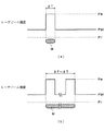
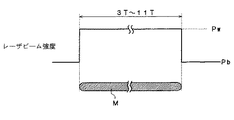
図9は、有機色素を用いた記録層を有するCD−Rに、データを記録する場合の代表的なパルス列パターンを示す図であり、EFM変調方式における3T信号ないし11T信号を記録する場合のパルス列パターンを示している。
図9に示されるように、CD−Rにデータを記録する場合には、一般に、形成すべき記録マークMの長さに相当する幅の記録パルスが用いられる(たとえば、特開2000−187842号公報参照)。
FIG. 9 is a diagram showing a typical pulse train pattern in the case of recording data on a CD-R having a recording layer using an organic dye, and a pulse train in the case of recording a 3T signal or an 11T signal in the EFM modulation method. The pattern is shown.
As shown in FIG. 9, when data is recorded on a CD-R, a recording pulse having a width corresponding to the length of the recording mark M to be formed is generally used (for example, Japanese Patent Laid-Open No. 2000-187842). See the official gazette).
すなわち、レーザビームの強度は、記録マークMを形成しないブランク領域においては、基底パワーPbに固定され、記録マークMを形成すべき領域において記録パワーPwに固定される。その結果、記録マークMを形成すべき領域においては、記録層に含まれる有機色素が分解、変質し、場合によっては、その領域が変形することによって、記録マークMが形成される。ここに、CD−Rの等倍速における記録線速度は約1.2m/secである。 That is, the intensity of the laser beam is fixed to the base power Pb in the blank area where the recording mark M is not formed, and is fixed to the recording power Pw in the area where the recording mark M is to be formed. As a result, in the region where the recording mark M is to be formed, the organic dye contained in the recording layer is decomposed and altered, and in some cases, the region is deformed to form the recording mark M. Here, the recording linear velocity at the same speed of the CD-R is about 1.2 m / sec.
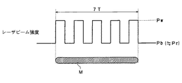
図10は、有機色素を用いた記録層を有するDVD−Rに、データを記録する場合の代表的なパルス列パターンを示す図であり、8/16変調方式における7T信号を記録する場合のパルス列パターンを示している。 FIG. 10 is a diagram showing a typical pulse train pattern when recording data on a DVD-R having a recording layer using an organic dye, and a pulse train pattern when recording a 7T signal in the 8/16 modulation method. Is shown.
DVD−Rに対しては、CD−Rに比して、高い記録線速度で、データの記録が行われるため、CD−Rにデータを記録する場合のように、記録マークMの長さに相当する幅の記録パルスを用いる場合には、良好な形状の記録マークMを形成することが困難である。 For DVD-R, since data is recorded at a higher recording linear velocity than CD-R, the length of recording mark M is set as in the case of recording data on CD-R. When a recording pulse having a corresponding width is used, it is difficult to form a recording mark M having a good shape.
このため、DVD−Rにデータを記録する場合には、図10に示されるように、形成すべき一つの記録マークMに対し、その長さに応じた数に分割されたパルス列を用いて、データが記録される。 For this reason, when recording data on a DVD-R, as shown in FIG. 10, a pulse train divided into a number corresponding to the length of one recording mark M to be formed is used. Data is recorded.
具体的には、nT信号(nは、8/16変調方式においては、3ないし11および14の整数である。)を形成するために、(n−2)個の分割パルスを用い、レーザビームのパワーは、分割パルスのピークにおいては、記録パワーPwに、その他においては、基底パワーPbに設定される。本明細書においては、このようなパルス列パターンを「基本パルス列パターン」という。ここに、DVD−Rの等倍速における記録線速度は約3.5m/secである。 Specifically, in order to form an nT signal (n is an integer of 3 to 11 and 14 in the 8/16 modulation system), (n−2) divided pulses are used to form a laser beam. Is set at the recording power Pw at the peak of the divided pulse and at the base power Pb at the other. In this specification, such a pulse train pattern is referred to as a “basic pulse train pattern”. Here, the recording linear velocity at the same speed of DVD-R is about 3.5 m / sec.
図10に示されるように、基本パルス列パターンにおいては、基底パワーPbのレベルは、データ再生に用いられる再生パワーPrと等しいか、あるいは、これに近いレベルに設定されている。 As shown in FIG. 10, in the basic pulse train pattern, the level of the base power Pb is set to a level that is equal to or close to the playback power Pr used for data playback.
一方、近年、データの記録密度が高められ、かつ、非常に高いデータ転送レートを実現可能な次世代型の光記録媒体が提案されている。 On the other hand, in recent years, a next-generation optical recording medium has been proposed in which the data recording density is increased and a very high data transfer rate can be realized.
このような次世代型の光記録媒体においては、高いデータ転送レートを実現するため、従来の光記録媒体に比べて、高い記録線速度で、データを記録することが要求されるが、一般に、追記型の光記録媒体においては、記録マークの形成に必要な記録パワーPwは、記録線速度の平方根に略比例するため、次世代型の光記録媒体に、データを記録する場合には、高出力の半導体レーザを用いることが必要とされる。 In such next-generation optical recording media, in order to achieve a high data transfer rate, it is required to record data at a higher recording linear velocity than conventional optical recording media. In the write once type optical recording medium, the recording power Pw necessary for forming the recording mark is substantially proportional to the square root of the recording linear velocity, so that when recording data on the next generation type optical recording medium, the recording power Pw is high. It is necessary to use an output semiconductor laser.
また、次世代型の光記録媒体においては、記録容量を高めるとともに、非常に高いデータ転送レートを実現するため、必然的に、データの記録・再生に用いるレーザビームのビームスポット径を非常に小さく絞ることが要求される。 In the next-generation optical recording medium, in addition to increasing the recording capacity and realizing a very high data transfer rate, the beam spot diameter of the laser beam used for data recording / reproducing is inevitably very small. It is required to squeeze.
レーザビームのビームスポット径を小さく絞るためには、レーザビームを集束するための対物レンズの開口数(NA)を0.7以上、たとえば、0.85程度まで大きくするとともに、レーザビームの波長λを450nm以下、たとえば、400nm程度まで、短くすることが必要になる。 In order to reduce the beam spot diameter of the laser beam, the numerical aperture (NA) of the objective lens for focusing the laser beam is increased to 0.7 or more, for example, about 0.85, and the wavelength λ of the laser beam is increased. Needs to be shortened to 450 nm or less, for example, about 400 nm.
しかしながら、780nmの波長λを有するレーザビームを発するCD用の半導体レーザや、650nmの波長λを有するレーザビームを発するDVD用の半導体レーザに比して、450nm以下の波長λを有する半導体レーザは出力が小さく、また、出力が高い半導体レーザは高価であるという問題がある。 However, as compared with a semiconductor laser for CD emitting a laser beam having a wavelength λ of 780 nm and a semiconductor laser for DVD emitting a laser beam having a wavelength λ of 650 nm, a semiconductor laser having a wavelength λ of 450 nm or less is output. However, there is a problem that a semiconductor laser having a small output and a high output is expensive.
その結果、次世代型の光記録媒体においては、基本パルス列パターンを用いて、高いデータ転送レートで、データを記録することが困難であり、とくに、5m/sec以上の記録線速度で、データを記録する場合に、深刻な問題となっていた。 As a result, in the next-generation optical recording medium, it is difficult to record data at a high data transfer rate using a basic pulse train pattern. In particular, data can be recorded at a recording linear velocity of 5 m / sec or more. It was a serious problem when recording.
したがって、本発明は、高い記録線速度で、追記型の光記録媒体に情報を記録することができる光記録媒体への情報記録方法を提供することを目的とするものである。 Accordingly, an object of the present invention is to provide an information recording method on an optical recording medium capable of recording information on a write-once type optical recording medium at a high recording linear velocity.
また、本発明の別の目的は、高い記録線速度で、追記型の光記録媒体に情報を記録することができる光記録媒体への情報記録装置を提供することにある。 Another object of the present invention is to provide an information recording apparatus for an optical recording medium capable of recording information on a write once optical recording medium at a high recording linear velocity.
さらに、本発明の他の目的は、高い記録線速度で、情報を記録することができる追記型の光記録媒体を提供することにある。 Another object of the present invention is to provide a write-once type optical recording medium capable of recording information at a high recording linear velocity.
本発明のかかる目的は、基板と前記基板上に形成された記録層を備えた追記型の光記録媒体に、少なくとも記録パワーPwおよび第一の基底パワーPb1を含むパルス列パターンにしたがって変調されたレーザビームを照射し、前記記録層を物理的及び/又は化学的に変化させて、前記記録層に少なくとも二つの記録マークを形成して、情報を記録する方法であって、5m/sec以上の第1の記録線速度で、情報を記録する場合の前記第一の基底パワーと前記記録パワーとの比をALとし、10m/sec以上の第2の記録線速度で、情報を記録する場合の前記第一の基底パワーと前記記録パワーとの比をAHとしたときに、AH>ALを満たすように、それぞれの第一の基底パワーおよび記録パワーを設定することを特徴とする光記録媒体への情報記録方法によって達成される。 An object of the present invention is to provide a write-once optical recording medium comprising a substrate and a recording layer formed on the substrate, and a laser modulated according to a pulse train pattern including at least the recording power Pw and the first base power Pb1. A method of recording information by irradiating a beam and physically and / or chemically changing the recording layer to form at least two recording marks on the recording layer, wherein the recording layer is recorded at a first level of 5 m / sec or more. In the case where information is recorded at a recording linear velocity of 1, the ratio of the first base power to the recording power when recording information is AL, and the information is recorded at a second recording linear velocity of 10 m / sec or more. Each of the first base power and the recording power is set so as to satisfy AH> AL, where AH is the ratio between the first base power and the recording power. It is achieved by method for recording information on.
本発明の好ましい実施態様においては、1.5×AL<AH<5.0×ALを満たすように、それぞれの第一の基底パワーおよび記録パワーが設定される。 In a preferred embodiment of the present invention, the respective first base power and recording power are set so as to satisfy 1.5 × AL <AH <5.0 × AL.
本発明のさらに好ましい実施態様においては、2.5×AL<AH<4.0×ALを満たすように、それぞれの第一の基底パワーおよび記録パワーが設定される。 In a further preferred embodiment of the present invention, the respective first base power and recording power are set so as to satisfy 2.5 × AL <AH <4.0 × AL.
本発明の好ましい実施態様においては、前記記録パワーからなるパルスが、前記記録マークの長さに対応する数の分割パルスによって構成されている。 In a preferred embodiment of the present invention, the pulse composed of the recording power is constituted by a number of divided pulses corresponding to the length of the recording mark.
本発明のさらに好ましい実施態様においては、前記記録パワーからなるパルスの後に、前記第一の基底パワーよりも強度の低い第二の基底パワーを含むパルス列パターンにしたがって、レーザビームのパワーを変調するように構成されている。 In a further preferred aspect of the present invention, the power of the laser beam is modulated in accordance with a pulse train pattern including a second base power having a lower intensity than the first base power after the pulse having the recording power. It is configured.
本発明の好ましい実施態様においては、前記光記録媒体に、450nm以下の波長を有するレーザビームを照射して、情報を記録するように構成されている。 In a preferred embodiment of the present invention, information is recorded by irradiating the optical recording medium with a laser beam having a wavelength of 450 nm or less.
本発明の好ましい実施態様においては、λ/NA≦640nmを満たす開口数NAを有する対物レンズおよび波長λを有するレーザビームを用い、前記対物レンズを介して、前記光記録媒体に、レーザビームを照射して、情報を記録するように構成されている。 In a preferred embodiment of the present invention, an objective lens having a numerical aperture NA satisfying λ / NA ≦ 640 nm and a laser beam having a wavelength λ are used, and the optical recording medium is irradiated with the laser beam through the objective lens. Thus, the information is recorded.
本発明の好ましい実施態様においては、前記光記録媒体が、さらに、光透過層を備え、前記記録層が、前記基板と前記光透過層の間に形成され、第一の反応層と第二の反応層を含み、光透過層と、前記光透過層を介して、レーザビームが照射されたときに、前記第一の反応層に主成分として含まれている元素と、前記第二の反応層に主成分として含まれている元素とが混合し、記録マークが形成されるように構成されている。 In a preferred embodiment of the present invention, the optical recording medium further comprises a light transmission layer, the recording layer is formed between the substrate and the light transmission layer, and the first reaction layer and the second reaction layer are formed. A reaction layer, a light transmission layer, an element contained as a main component in the first reaction layer when the laser beam is irradiated through the light transmission layer, and the second reaction layer The recording mark is formed by mixing with the elements contained as the main component.
本発明のさらに好ましい実施態様においては、前記第二の反応層が、前記第一の反応層に接するように、形成されている。 In a further preferred embodiment of the present invention, the second reaction layer is formed so as to be in contact with the first reaction layer.
本発明の前記目的はまた、基板と、前記基板上に形成された記録層を備えた追記型の光記録媒体に、少なくとも記録パワーPwおよび第一の基底パワーPb1を含むパルス列パターンにしたがって変調されたレーザビームを照射するレーザ照射手段を備えた光記録媒体へのデータの記録装置であって、5m/sec以上の第1の記録線速度で、情報を記録する場合の前記第一の基底パワーと前記記録パワーとの比をALとし、10m/sec以上の第2の記録線速度で、情報を記録する場合の前記第一の基底パワーと前記記録パワーとの比をAHとしたときに、前記レーザ照射手段が、AH>ALを満たすように、それぞれの第一の基底パワーおよび記録パワーを設定することを特徴とする光記録媒体への情報記録装置によって達成される。 The object of the present invention is also modulated on a write-once optical recording medium having a substrate and a recording layer formed on the substrate according to a pulse train pattern including at least the recording power Pw and the first base power Pb1. An apparatus for recording data on an optical recording medium having a laser irradiation means for irradiating a laser beam, wherein the first base power for recording information at a first recording linear velocity of 5 m / sec or more When the ratio of the first base power and the recording power in the case of recording information at a second recording linear velocity of 10 m / sec or more is AH, the ratio between the recording power and the recording power is AH. This is achieved by an information recording apparatus for an optical recording medium, wherein the laser irradiation means sets the respective first base power and recording power so as to satisfy AH> AL.
本発明の好ましい実施態様においては、1.5×AL<AH<5.0×ALを満たすように、それぞれの第一の基底パワーおよび記録パワーが設定される。 In a preferred embodiment of the present invention, the respective first base power and recording power are set so as to satisfy 1.5 × AL <AH <5.0 × AL.
本発明のさらに好ましい実施態様においては、2.5×AL<AH<4.0×ALを満たすように、それぞれの第一の基底パワーおよび記録パワーが設定される。 In a further preferred embodiment of the present invention, the respective first base power and recording power are set so as to satisfy 2.5 × AL <AH <4.0 × AL.
本発明のさらに好ましい実施態様においては、前記記録パワーからなるパルスが、前記記録マークの長さに対応する数の分割パルスによって構成されている。 In a further preferred aspect of the present invention, the pulse having the recording power is constituted by a number of divided pulses corresponding to the length of the recording mark.
本発明のさらに好ましい実施態様においては、前記記録パワーからなるパルスの後に、前記第一の基底パワーよりも強度の低い第二の基底パワーを含むパルス列パターンにしたがって、レーザビームのパワーを変調するように構成されている。 In a further preferred aspect of the present invention, the power of the laser beam is modulated in accordance with a pulse train pattern including a second base power having a lower intensity than the first base power after the pulse having the recording power. It is configured.
本発明の好ましい実施態様においては、前記光記録媒体に、450nm以下の波長を有するレーザビームを照射して、情報を記録するように構成されている。 In a preferred embodiment of the present invention, information is recorded by irradiating the optical recording medium with a laser beam having a wavelength of 450 nm or less.
本発明の好ましい実施態様においては、λ/NA≦640nmを満たす開口数NAを有する対物レンズおよび波長λを有するレーザビームを用い、前記対物レンズを介して、前記光記録媒体に、レーザビームを照射して、情報を記録するように構成されている。 In a preferred embodiment of the present invention, an objective lens having a numerical aperture NA satisfying λ / NA ≦ 640 nm and a laser beam having a wavelength λ are used, and the optical recording medium is irradiated with the laser beam through the objective lens. Thus, the information is recorded.
本発明の前記目的はまた、基板と、前記基板上に形成された記録層を備え、少なくとも記録パワーおよび第一の基底パワーを含むパルス列パターンにしたがって変調されたレーザビームが照射されて、前記記録層が物理的及び/又は化学的に変化し、前記記録層に少なくとも二つの記録マークが形成されて、情報が記録されるように構成された追記型の光記録媒体であって、5m/sec以上の第1の記録線速度で、情報を記録する場合の前記第一の基底パワーと前記記録パワーとの比をALとし、10m/sec以上の第2の記録線速度で、情報を記録する場合の前記第一の基底パワーと前記記録パワーとの比をAHとしたときに、AH>ALを満たすように、それぞれの第一の基底パワーおよび記録パワーを設定して、記録マークを形成するために必要な記録条件設定用データが記録されていることを特徴とする光記録媒体によって達成される。 The object of the present invention also includes a substrate and a recording layer formed on the substrate, and is irradiated with a laser beam modulated according to a pulse train pattern including at least a recording power and a first base power, and the recording A write-once optical recording medium configured to record information by forming a layer physically and / or chemically and forming at least two recording marks on the recording layer, wherein the recording layer is 5 m / sec. When recording information at the first recording linear velocity, information is recorded at a second recording linear velocity of 10 m / sec or more, where AL is the ratio of the first base power to the recording power. When the ratio between the first base power and the recording power in the case is AH, the first base power and the recording power are set so as to satisfy AH> AL, and a recording mark is formed. Recording condition setting data required in order is achieved by an optical recording medium characterized in that it is recorded.
本発明の好ましい実施態様においては、光記録媒体は、さらに、光透過層と、前記基板と前記光透過層の間に形成された第一の反応層と第二の反応層を含む記録層を備え、前記光透過層を介して、レーザビームが照射されたときに、前記第一の反応層に主成分として含まれている元素と、前記第二の反応層に主成分として含まれている元素とが混合し、記録マークが形成されるように構成されている。 In a preferred embodiment of the present invention, the optical recording medium further comprises a light transmission layer, and a recording layer including a first reaction layer and a second reaction layer formed between the substrate and the light transmission layer. An element included as a main component in the first reaction layer and a main component included in the second reaction layer when a laser beam is irradiated through the light transmission layer The recording marks are formed by mixing with the elements.
本発明のさらに好ましい実施態様においては、前記第二の反応層が、前記第一の反応層に接するように、形成されている。 In a further preferred embodiment of the present invention, the second reaction layer is formed so as to be in contact with the first reaction layer.
本発明のさらに好ましい実施態様においては、前記光透過層が、10ないし300nmの厚さを有するように形成されている。 In a further preferred embodiment of the present invention, the light transmission layer is formed to have a thickness of 10 to 300 nm.
本発明のさらに好ましい実施態様においては、1.5×AL<AH<5.0×ALを満たすように、それぞれの第一の基底パワーおよび記録パワーが設定されている。 In a further preferred embodiment of the present invention, the respective first base power and recording power are set so as to satisfy 1.5 × AL <AH <5.0 × AL.
本発明のさらに好ましい実施態様においては、2.5×AL<AH<4.0×ALを満たすように、それぞれの第一の基底パワーおよび記録パワーが設定されている。 In a further preferred embodiment of the present invention, the respective first base power and recording power are set so as to satisfy 2.5 × AL <AH <4.0 × AL.
本発明のさらに好ましい実施態様においては、前記記録パワーからなるパルスが、前記記録マークの長さに対応する数の分割パルスによって構成されている。 In a further preferred aspect of the present invention, the pulse having the recording power is constituted by a number of divided pulses corresponding to the length of the recording mark.
本発明のさらに好ましい実施態様においては、前記記録パワーからなるパルスの後に、前記第一の基底パワーよりも強度の低い第二の基底パワーを含むパルス列パターンにしたがって、レーザビームのパワーを変調するように構成されている。 In a further preferred aspect of the present invention, the power of the laser beam is modulated in accordance with a pulse train pattern including a second base power having a lower intensity than the first base power after the pulse having the recording power. It is configured.
本発明によれば、高い記録線速度で、追記型の光記録媒体に情報を記録することができる光記録媒体への情報記録方法を提供することが可能になる。 According to the present invention, it is possible to provide an information recording method on an optical recording medium that can record information on a write-once type optical recording medium at a high recording linear velocity.
また、本発明によれば、高い記録線速度で、追記型の光記録媒体に情報を記録することができる光記録媒体への情報記録装置を提供することが可能になる。 Further, according to the present invention, it is possible to provide an information recording apparatus for an optical recording medium capable of recording information on a write-once type optical recording medium at a high recording linear velocity.
さらに、本発明によれば、高い記録線速度で、情報を記録することができる追記型の光記録媒体を提供することが可能になる。 Furthermore, according to the present invention, it becomes possible to provide a write-once type optical recording medium capable of recording information at a high recording linear velocity.
以下、添付図面に基づいて、本発明の好ましい実施態様につき、詳細に説明を加える。 Hereinafter, preferred embodiments of the present invention will be described in detail with reference to the accompanying drawings.
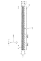
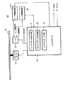
図1は、本発明の好ましい実施態様にかかる光記録媒体の構造を示す略断面図である。 FIG. 1 is a schematic cross-sectional view showing the structure of an optical recording medium according to a preferred embodiment of the present invention.
図1に示されるように、本実施態様にかかる光記録媒体10は、追記型の光記録媒体として構成され、基板11と、基板11の表面上に形成された反射層12と、反射層12の表面上に形成された第二の誘電体層13と、第二の誘電体層13の表面上に形成された記録層14と、記録層14の表面上に設けられた第一の誘電体層15と、第一の誘電体層15の表面上に形成された光透過層16を備えている。図1に示されるように、記録層14は、第二の誘電体層13の表面上に形成された第二の反応層32と、第二の反応層32の表面上に形成された第一の反応層31を含んでいる。
As shown in FIG. 1, an
図1に示されるように、光記録媒体10の中央部分には、センターホール17が形成されている。
As shown in FIG. 1, a center hole 17 is formed in the central portion of the
本実施態様においては、図1に示されるように、光透過層16の表面に、レーザビームL10が照射されて、光記録媒体10にデータが記録され、光記録媒体10から、データが再生されるように構成されている。
In this embodiment, as shown in FIG. 1, the surface of the light transmission layer 16 is irradiated with a laser beam L10 to record data on the
基板11は、光記録媒体10に求められる機械的強度を確保するための支持体として、機能する。
The substrate 11 functions as a support for ensuring the mechanical strength required for the
基板11を形成するための材料は、光記録媒体10の支持体として機能することができれば、とくに限定されるものではない。基板11は、たとえば、ガラス、セラミックス、樹脂などによって、形成することができる。これらのうち、成形の容易性の観点から、樹脂が好ましく使用される。このような樹脂としては、ポリカーボネート樹脂、アクリル樹脂、エポキシ樹脂、ポリスチレン樹脂、ポリエチレン樹脂、ポリプロピレン樹脂、シリコーン樹脂、フッ素系樹脂、ABS樹脂、ウレタン樹脂などが挙げられる。これらの中でも、加工性、光学特性などの点から、ポリカーボネート樹脂がとくに好ましい。
The material for forming the substrate 11 is not particularly limited as long as it can function as a support for the
本実施態様においては、基板11は、約1.1mmの厚さを有している。 In this embodiment, the substrate 11 has a thickness of about 1.1 mm.
図1に示されるように、基板11の表面には、交互に、グルーブ11aおよびランド11bが形成されている。基板11の表面に形成されたグルーブ11aおよび/またはランド11bは、データを記録する場合およびデータを再生する場合において、レーザビームL10のガイドトラックとして、機能する。 As shown in FIG. 1, grooves 11 a and lands 11 b are alternately formed on the surface of the substrate 11. The groove 11a and / or land 11b formed on the surface of the substrate 11 functions as a guide track for the laser beam L10 when recording data and reproducing data.
反射層12は、光透過層16を介して、入射したレーザビームL10を反射し、再び、光透過層16から出射させる機能を有している。
The
反射層12の厚さは、とくに限定されるものではないが、10nmないし300nmであることが好ましく、20nmないし200nmであることが、とくに好ましい。
The thickness of the
反射層12を形成するための材料は、レーザビームを反射できればよく、とくに限定されるものではなく、Mg、Al、Ti、Cr、Fe、Co、Ni、Cu、Zn、Ge、Ag、Pt、Auなどによって、反射層12を形成することができる。これらのうち、高い反射率を有しているAl、Au、Ag、Cu、または、AgとCuとの合金などのこれらの金属の少なくとも1つを含む合金などの金属材料が、反射層12を形成するために、好ましく用いられる。
The material for forming the
反射層12は、レーザビームL10を用いて、第一の反応層31および第二の反応層32に光記録されたデータを再生するときに、多重干渉効果によって、記録部と未記録部との反射率の差を大きくして、高い再生信号(C/N比)を得るために、設けられている。
The
第一の誘電体層15および第二の誘電体層13は、記録層14を保護する役割を担っている。したがって、第一の誘電体層15および第二の誘電体層13により、長期間にわたって、光記録されたデータの劣化を効果的に防止することができる。また、第二の誘電体層13は、基板11などの熱変形を防止する効果があり、したがって、変形に伴うジッターの悪化を効果的に防止することが可能になる。
The first dielectric layer 15 and the second dielectric layer 13 have a role of protecting the
第一の誘電体層15および第2の誘電体層13を形成するための誘電体材料は、透明な誘電体材料であれば、とくに限定されるものではなく、たとえば、酸化物、硫化物、窒化物またはこれらの組み合わせを主成分とする誘電体材料によって、第一の誘電体層15および第二の誘電体層13を形成することができる。より具体的には、基板11などの熱変形を防止し、記録層14を保護するために、第一の誘電体層15および第二の誘電体層13が、Al2O3、AlN、ZnO、ZnS、GeN、GeCrN、CeO、SiO、SiO2、SiNおよびSiCよりなる群から選ばれる少なくとも1種の誘電体材料を主成分として含んでいることが好ましく、ZnS・SiO2を主成分として含んでいることがより好ましい。
The dielectric material for forming the first dielectric layer 15 and the second dielectric layer 13 is not particularly limited as long as it is a transparent dielectric material. For example, oxides, sulfides, The first dielectric layer 15 and the second dielectric layer 13 can be formed of a dielectric material mainly composed of nitride or a combination thereof. More specifically, in order to prevent thermal deformation of the substrate 11 and the like and protect the
第一の誘電体層15と第二の誘電体層13は、互いに同じ誘電体材料によって形成されていてもよいが、異なる誘電体材料によって形成されていてもよい。さらに、第一の誘電体層15および第二の誘電体層13の少なくとも一方が、複数の誘電体膜からなる多層構造であってもよい。 The first dielectric layer 15 and the second dielectric layer 13 may be formed of the same dielectric material, but may be formed of different dielectric materials. Furthermore, at least one of the first dielectric layer 15 and the second dielectric layer 13 may have a multilayer structure including a plurality of dielectric films.
なお、本明細書において、誘電体層が、誘電体材料を主成分として含むとは、誘電体層に含まれている誘電体材料の中で、その誘電体材料の含有率が最も大きいことをいう。また、ZnS・SiO2は、ZnSとSiO2との混合物を意味する。 In this specification, that the dielectric layer contains a dielectric material as a main component means that the dielectric material has the largest content ratio among the dielectric materials contained in the dielectric layer. Say. ZnS · SiO 2 means a mixture of ZnS and SiO 2 .
第一の誘電体層15および第二の誘電体層13の層厚は、とくに限定されるものではないが、3ないし200nmであることが好ましい。第一の誘電体層15あるいは第二の誘電体層13の層厚が3nm未満であると、上述した効果が得られにくくなる。一方、第一の誘電体層15あるいは第二の誘電体層13の層厚が200nmを越えると、成膜に要する時間が長くなり、光記録媒体10の生産性が低下するおそれがあり、さらに、第一の誘電体層15あるいは第二の誘電体層13のもつ応力によって、光記録媒体10にクラックが発生するおそれがある。
The thicknesses of the first dielectric layer 15 and the second dielectric layer 13 are not particularly limited, but are preferably 3 to 200 nm. When the thickness of the first dielectric layer 15 or the second dielectric layer 13 is less than 3 nm, the above-described effect is hardly obtained. On the other hand, if the thickness of the first dielectric layer 15 or the second dielectric layer 13 exceeds 200 nm, the time required for film formation becomes long, and the productivity of the
記録層14は、記録マークが形成されて、データが記録される層であり、第二の誘電体層13の表面上に形成された第二の反応層32と、第二の反応層32の表面上に形成された第一の反応層31を含んでいる。図1に示されるように、本実施態様においては、第一の反応層31は、光透過層16側に配置され、第二の反応層32は、基板11側に配置されている。
The
本実施態様においては、第一の反応層31は、Al、Si、Ge、C、Sn、Au、Zn、Cu、B、Mg、Ti、Mn、Fe、Ga、Zr、AgおよびPtよりなる群から選ばれた元素を主成分として含み、第二の反応層32は、Al、Si、Ge、C、Sn、Au、Zn、Cu、B、Mg、Ti、Mn、Fe、Ga、Zr、AgおよびPtよりなる群から選ばれた元素で、第一の反応層31に主成分として含まれている元素とは異なる元素を主成分として含んでいる。
In this embodiment, the first reaction layer 31 is made of Al, Si, Ge, C, Sn, Au, Zn, Cu, B, Mg, Ti, Mn, Fe, Ga, Zr, Ag, and Pt. The
第一の反応層31および第二の反応層32が、このような元素を主成分として含んでいる場合には、光記録媒体10の長期間の保存に対する信頼性を向上させることが可能になる。
When the first reaction layer 31 and the
また、これらの元素は、環境に関する負荷が小さく、地球環境を害するおそれがない。 In addition, these elements have a small environmental load and do not cause harm to the global environment.
再生信号のノイズレベルを低く抑えるためには、第一の反応層31および第二の反応層32に、主成分として含まれている元素以外の元素が添加されていることが好ましい。このような元素を添加することによって、第一の反応層31および第二の反応層32の表面平滑性を向上させて、再生信号のノイズレベルを低く抑えることが可能になるとともに、光記録媒体10の長期間の保存に対する信頼性を向上させることが可能になる。
In order to suppress the noise level of the reproduction signal to be low, it is preferable that an element other than the element included as the main component is added to the first reaction layer 31 and the
第一の反応層31および第二の反応層32に添加される元素は、一種類である必要はなく、第一の反応層31および第二の反応層32に、二種類以上の元素を添加することもできる。
The elements added to the first reaction layer 31 and the
記録層14の層厚は、とくに限定されるものではないが、2nmないし40nmの厚さを有するように、記録層14を形成することが好ましく、2nmないし20nmの厚さを有するように、記録層14を形成することがより好ましい。このような厚さを有するように、記録層14を形成することによって、第一の反応層31および第二の反応層32の表面平滑性を向上させて、再生信号のノイズレベルを低く抑えることができ、また、充分に高いレベルの再生信号(C/N比)を得ることが可能になるとともに、記録感度を十分に向上させることが可能になる。
The thickness of the
第一の反応層31および第二の反応層32のそれぞれの層厚は、とくに限定されるものではないが、再生信号のノイズレベルを低く抑えるとともに、記録感度を十分に向上させ、データを記録する前後の反射率の変化を十分に大きくするためには、第一の反応層31の層厚が、1nmないし30nmであり、第二の反応層32の層厚が、1nmないし30nmであることが好ましい。さらに、第一の反応層31の層厚と第二の反応層32の層厚との比(第一の反応層31の層厚/第二の反応層32の層厚)は、0.2ないし5.0であることが好ましい。
The thicknesses of the first reaction layer 31 and the
光透過層16は、レーザビームL10が透過する層であり、10μmないし300μmの厚さを有していることが好ましく、より好ましくは、光透過層16は、50μmないし150μmの厚さを有している。 The light transmission layer 16 is a layer through which the laser beam L10 is transmitted, and preferably has a thickness of 10 μm to 300 μm. More preferably, the light transmission layer 16 has a thickness of 50 μm to 150 μm. ing.
光透過層16を形成するための材料は、とくに限定されるものではないが、塗布によって、光透過層16を形成する場合には、紫外線硬化性のアクリル樹脂やエポキシ樹脂などが好ましく用いられる。 The material for forming the light transmission layer 16 is not particularly limited, but when the light transmission layer 16 is formed by coating, an ultraviolet curable acrylic resin or epoxy resin is preferably used.
光透過層16は、第一の誘電体層15の表面に、光透過性樹脂によって形成されたシートを、接着剤を用いて、接着することによって、形成されてもよい。 The light transmission layer 16 may be formed by adhering a sheet formed of a light transmission resin to the surface of the first dielectric layer 15 using an adhesive.
以上のような構成を有する光記録媒体10は、たとえば、以下のようにして、製造される。
The
まず、グルーブ11aおよびランド11bが形成された基板11の表面上に、反射層12が形成される。
First, the
反射層12は、たとえば、反射層12の構成元素を含む化学種を用いた気相成長法によって、形成することができる。気相成長法としては、真空蒸着法、スパッタリング法などが挙げられる。
The
次いで、反射層12の表面上に、第二の誘電体層13が形成される。
Next, the second dielectric layer 13 is formed on the surface of the
第二の誘電体層13は、たとえば、第二の誘電体層13の構成元素を含む化学種を用いた気相成長法によって、形成することができる。気相成長法としては、真空蒸着法、スパッタリング法などが挙げられる。 The second dielectric layer 13 can be formed by, for example, a vapor phase growth method using a chemical species containing a constituent element of the second dielectric layer 13. Examples of the vapor deposition method include a vacuum deposition method and a sputtering method.
さらに、第二の誘電体層13の表面上に、第二の反応層32が形成される。第二の反応層32も、第二の誘電体層13と同様にして、第二の反応層32の構成元素を含む化学種を用いた気相成長法によって、形成することができる。
Further, the
次いで、第二の反応層32の表面上に、第一の反応層31が形成される。第一の反応層31も、第一の反応層31の構成元素を含む化学種を用いた気相成長法によって形成することができる。
Next, the first reaction layer 31 is formed on the surface of the
さらに、第一の反応層31の表面上に、第一の誘電体層15が形成される。第一の誘電体層15もまた、第一の誘電体層15の構成元素を含む化学種を用いた気相成長法によって、形成することができる。 Furthermore, the first dielectric layer 15 is formed on the surface of the first reaction layer 31. The first dielectric layer 15 can also be formed by a vapor phase growth method using a chemical species containing a constituent element of the first dielectric layer 15.
最後に、第一の誘電体層15の表面上に、光透過層16が形成される。光透過層16は、たとえば、粘度調整されたアクリル系の紫外線硬化性樹脂あるいはエポキシ系の紫外線硬化性樹脂を、スピンコーティング法などによって、第一の誘電体層15の表面に塗布して、塗膜を形成し、紫外線を照射して、塗膜を硬化させることによって、形成することができる。 Finally, the light transmission layer 16 is formed on the surface of the first dielectric layer 15. The light transmission layer 16 is formed by applying a viscosity-adjusted acrylic UV curable resin or epoxy UV curable resin to the surface of the first dielectric layer 15 by spin coating or the like. It can be formed by forming a film, irradiating it with ultraviolet rays, and curing the coating film.
以上のようにして、光記録媒体10が製造される。
The
以上のような構成を有する光記録媒体10に、たとえば、以下のようにして、データが記録される。
Data is recorded on the
まず、図1に示されるように、所定のパワーを有するレーザビームL10が、光透過層16を介して、記録層14に照射される。
First, as shown in FIG. 1, the
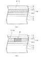
図2(a)は、図1に示された光記録媒体の一部拡大略断面図であり、レーザビームL10が、記録層14に照射される前の状態を示している。
FIG. 2A is a partially enlarged schematic sectional view of the optical recording medium shown in FIG. 1, and shows a state before the
データを高い記録密度で、光記録媒体10に記録するためには、450nm以下の波長を有するレーザビームL10を、開口数NAが0.7以上の対物レンズ(図示せず)を用いて、光記録媒体10上に集束することが好ましく、λ/NA≦640nmであることがより好ましい。この場合には、第一の反応層31の表面におけるレーザビームL10のビームスポット径は0.65μm以下になる。
In order to record data on the
本実施態様においては、405nmの波長を有するレーザビームL10が、開口数が0.85の対物レンズを用いて、第一の反応層31の表面におけるレーザビームL10のビームスポット径が約0.43μmとなるように、光記録媒体10上に集束される。
In the present embodiment, a laser beam L10 having a wavelength of 405 nm has a beam spot diameter of about 0.43 μm on the surface of the first reaction layer 31 using an objective lens having a numerical aperture of 0.85. To be focused on the
その結果、レーザビームL10が照射された領域において、第一の反応層31に主成分として含まれた元素と、第二の反応層32に主成分として含まれた元素とが混合されて、図2(b)に示されるように、第一の反応層31に主成分として含まれた元素と、第二の反応層32に主成分として含まれた元素とが混合されて、混合領域Mが形成される。
As a result, in the region irradiated with the laser beam L10, the element included as the main component in the first reaction layer 31 and the element included as the main component in the
第一の反応層31に主成分として含まれた元素と、第二の反応層32に主成分として含まれた元素とが混合されると、その領域の反射率が大きく変化し、したがって、こうして形成された混合領域Mの反射率は、その周囲の領域の反射率と大きく異なることになるので、混合領域Mを記録マークMとして用いて、光記録媒体10にデータを記録し、光記録媒体10からデータを再生することが可能になる。
When the element included as the main component in the first reaction layer 31 and the element included as the main component in the
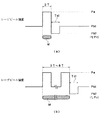
図3は、1,7RLL変調方式を用いた場合の第1のパルス列パターンを示す図であり、図3(a)は、2T信号を形成する場合のパルス列パターンを示し、図3(b)は、3T信号ないし8T信号を形成する場合のパルス列パターンを示している。 FIG. 3 is a diagram showing a first pulse train pattern when the 1,7RLL modulation method is used. FIG. 3 (a) shows a pulse train pattern when a 2T signal is formed, and FIG. The pulse train pattern when 3T signal to 8T signal is formed is shown.
図3(a)および図3(b)に示されるように、第1のパルス列パターンにおいては、記録マークMを形成するための記録パルスが、(n−1)個に分割され、レーザビームL10のパワーは、各分割パルスのピークにおいて、記録パワーPwに、その他の期間において、データを再生する場合のレーザビームL10のパワーである再生パワーPrよりも高い第一の基底パワーPb1に設定される。すなわち、第1のパルス列パターンは、図10に示された基本パルス列パターンにおける基底パワーPbが、再生パワーPrにほぼ等しいレベルから、再生パワーPrよりも高い第一の基底パワーPb1に高められた構成を有している。 As shown in FIGS. 3A and 3B, in the first pulse train pattern, the recording pulse for forming the recording mark M is divided into (n−1) pieces, and the laser beam L10. Is set to the recording power Pw at the peak of each divided pulse, and to the first base power Pb1 higher than the reproduction power Pr that is the power of the laser beam L10 when reproducing data in other periods. . That is, the first pulse train pattern has a configuration in which the base power Pb in the basic pulse train pattern shown in FIG. 10 is increased from a level substantially equal to the playback power Pr to the first base power Pb1 higher than the playback power Pr. have.
記録パワーPwは、レーザビームL10の照射によって、第一の反応層31に主成分として含まれる元素と、第2の反応層32に主成分として含まれる元素が加熱されて、混合し、記録マークMが形成されるような高いレベルに設定され、第一の基底パワーPb1は、再生パワーPrよりも高いが、第一の基底パワーPb1のレーザビームL10が照射されても、第一の反応層31に主成分として含まれる元素と、第2の反応層32に主成分として含まれる元素が実質的に混合することがないような低いレベルに設定される。
The recording power Pw is obtained by heating and mixing the element contained as the main component in the first reaction layer 31 and the element contained as the main component in the
第一の基底パワーPb1と記録パワーPwとの比Pb1/Pwは、0.1ないし0.5であることが好ましく、10m/sec以上の記録線速度で、データを記録する場合には、比Pb1/Pwは、0.2ないし0.5であることが好ましく、0.3ないし0.45であると、より好ましい。 The ratio Pb1 / Pw between the first base power Pb1 and the recording power Pw is preferably 0.1 to 0.5, and when recording data at a recording linear velocity of 10 m / sec or more, the ratio Pb1 / Pw is preferably 0.2 to 0.5, and more preferably 0.3 to 0.45.
また、記録線速度VLで、データを記録する場合の第一の基底パワーPb1と記録パワーPwとの比Pb1/PwをALとし、記録線速度VLよりも高い記録線速度VHで、データを記録する場合の第一の基底パワーPb1と記録パワーPwとの比Pb1/PwをAHとした場合、AHがAlよりも大きくなるように、第一の基底パワーPb1と記録パワーPwを設定することが好ましく、1.5×AL<AH<5.0×ALとなるように、第一の基底パワーPb1と記録パワーPwを設定することがより好ましく、2.5×AL<AH<4.0×ALとなるように、第一の基底パワーPb1と記録パワーPwを設定することが最も好ましい。 Further, when recording data at the recording linear velocity VL, the ratio Pb1 / Pw between the first base power Pb1 and the recording power Pw when recording data is AL, and the data is recorded at a recording linear velocity VH higher than the recording linear velocity VL. When the ratio Pb1 / Pw between the first base power Pb1 and the recording power Pw is AH, the first base power Pb1 and the recording power Pw may be set so that AH is larger than Al. More preferably, the first base power Pb1 and the recording power Pw are set so that 1.5 × AL <AH <5.0 × AL, and 2.5 × AL <AH <4.0 ×. Most preferably, the first base power Pb1 and the recording power Pw are set so as to be AL.
このように、第1のパルス列パターンを構成することによって、記録マークMを形成すべき領域においては、記録パワーPwによる加熱が、第一の基底パワーPb1によって補助されて、記録マークMの形成が促進される一方で、記録マークMの間のブランク領域において、第一の基底パワーPb1を有するレーザビームL10によって、第一の反応層31に主成分として含まれる元素と、第二の反応層32に主成分として含まれる元素とが混合して、記録マークMが形成されることが防止される。
In this way, by forming the first pulse train pattern, in the region where the recording mark M is to be formed, the heating by the recording power Pw is assisted by the first base power Pb1, and the recording mark M is formed. On the other hand, in the blank region between the recording marks M, the element contained as the main component in the first reaction layer 31 and the
したがって、第1のパルス列パターンを用いて、レーザビームL10のパワーを変調し、光記録媒体10にデータを記録する場合には、より低い記録パワーPwを有するレーザビームL10を用いて、記録マークMを形成することができ、記録線速度を5m/sec以上に高めて、高いデータ転送レートを実現することが可能になる。
Therefore, when the power of the laser beam L10 is modulated using the first pulse train pattern and data is recorded on the
図4は、1,7RLL変調方式を用いた場合の第2のパルス列パターンを示す図であり、図4(a)は、2T信号を形成する場合のパルス列パターンを示し、図4(b)は、3T信号ないし8T信号を形成する場合のパルス列パターンを示している。 FIG. 4 is a diagram showing a second pulse train pattern when the 1,7RLL modulation method is used. FIG. 4 (a) shows a pulse train pattern when a 2T signal is formed, and FIG. The pulse train pattern when 3T signal to 8T signal is formed is shown.
図4(a)および図4(b)に示されるように、第2のパルス列パターンにおいては、記録マークMを形成するための記録パルスが、(n−1)個に分割され、レーザビームL10のパワーは、各分割パルスのピークにおいて、記録パワーPwに、最後の分割パルスの直後において、第2の基底パワーPb2に、その他の期間において、第一の基底パワーPb1に設定される。図4に示されるように、第一の基底パワーPb1および第2の基底パワーPb2は、Pb1>Pb2となるように設定されており、第2の基底パワーPb2は、再生パワーPrと同じレベルあるいは再生パワーPrに近いレベルに設定されている。 As shown in FIGS. 4A and 4B, in the second pulse train pattern, the recording pulse for forming the recording mark M is divided into (n−1) pieces, and the laser beam L10. Is set to the recording power Pw at the peak of each divided pulse, to the second base power Pb2 immediately after the last divided pulse, and to the first base power Pb1 in other periods. As shown in FIG. 4, the first base power Pb1 and the second base power Pb2 are set so that Pb1> Pb2, and the second base power Pb2 is the same level as the reproduction power Pr or It is set to a level close to the reproduction power Pr.
したがって、第2のパルス列パターンは、図10に示された基本パルス列パターンにおける最後の分割パルスの直後に、レーザビームL10のパワーが、第2の基底パワーPb2となる冷却期間Tclが挿入され、冷却期間Tclを除いて、図10に示された基本パルス列パターンにおける基底パワーPbが、再生パワーPrにほぼ等しいレベルから、再生パワーPrよりも高い第一の基底パワーPb1に高められた構成を有している。 Accordingly, in the second pulse train pattern, a cooling period Tcl in which the power of the laser beam L10 becomes the second base power Pb2 is inserted immediately after the last divided pulse in the basic pulse train pattern shown in FIG. Except for the period Tcl, the base power Pb in the basic pulse train pattern shown in FIG. 10 is increased from a level substantially equal to the reproduction power Pr to the first base power Pb1 higher than the reproduction power Pr. ing.
第2のパルス列パターンにおいても、記録パワーPwは、レーザビームL10の照射によって、第一の反応層31に主成分として含まれる元素と、第2の反応層32に主成分として含まれる元素が加熱されて、混合し、記録マークMが形成されるような高いレベルに設定され、第一の基底パワーPb1は、再生パワーPrよりも高いが、第一の基底パワーPb1のレーザビームL10が照射されても、第一の反応層31に主成分として含まれる元素と、第2の反応層32に主成分として含まれる元素が実質的に混合することがないような低いレベルに設定される。
Also in the second pulse train pattern, the recording power Pw is heated by the element included as the main component in the first reaction layer 31 and the element included as the main component in the
第一の基底パワーPb1と記録パワーPwの比Pb1/Pwは、第1のパルス列パターンを同様に設定される。 The ratio Pb1 / Pw between the first base power Pb1 and the recording power Pw is set similarly to the first pulse train pattern.
このように、第2のパルス列パターンを構成することによって、記録マークMを形成すべき領域においては、記録パワーPwによる加熱が、第一の基底パワーPb1によって補助されて、記録マークMの形成が促進される一方で、記録マークMの間のブランク領域において、第一の基底パワーPb1を有するレーザビームL10によって、第一の反応層31に主成分として含まれる元素と、第二の反応層32に主成分として含まれる元素とが混合して、記録マークMが形成されることが防止される。
In this way, by forming the second pulse train pattern, in the region where the recording mark M is to be formed, the heating by the recording power Pw is assisted by the first base power Pb1, so that the recording mark M is formed. On the other hand, in the blank region between the recording marks M, the element contained as the main component in the first reaction layer 31 and the
したがって、第2のパルス列パターンを用いて、レーザビームL10のパワーを変調し、光記録媒体10にデータを記録する場合には、より低い記録パワーPwを有するレーザビームL10を用いて、記録マークMを形成することができ、記録線速度を5m/sec以上に高めて、高いデータ転送レートを実現することが可能になる。
Therefore, when the power of the laser beam L10 is modulated using the second pulse train pattern and data is recorded on the
さらに、第2のパルス列パターンにおいては、最後の分割パルスの直後に、レーザビームL10のパワーが、第2の基底パワーPb2となる冷却期間Tclが挿入されているので、記録マークMを形成するために照射した記録パワーPwを有するレーザビームL10によって、加熱された記録マークMの後縁部が効果的に冷却され、記録マークMの後縁部よりもレーザビームの進行方向側の領域において、第一の反応層31に主成分として含まれる元素と、第2の反応層32に主成分として含まれる元素とが混合することが防止され、したがって、記録マークMの後縁部がずれることを効果的に防止して、記録マークMの長さを所望の長さに制御することが可能になる。
Further, in the second pulse train pattern, immediately after the last divided pulse, a cooling period Tcl in which the power of the laser beam L10 becomes the second base power Pb2 is inserted, so that the recording mark M is formed. The trailing edge of the heated recording mark M is effectively cooled by the laser beam L10 having the recording power Pw applied to the first recording medium, and in the region closer to the laser beam traveling direction than the trailing edge of the recording mark M, It is possible to prevent an element contained as a main component in one reaction layer 31 and an element contained as a main component in the
本実施態様によれば、記録マークMを形成するためのレーザビームL10の記録パルスを(n−a)個(aは「0」、「1」または「2」であり、8/16変調方式においては「2」、1,7RLL変調方式においては「1」とすることが好ましい。)に分割するとともに、第一の基底パワーPb1と記録パワーPwとの比Pb1/Pwが、0.1ないし0.5となるように、第一の基底パワーPb1のレベルおよび記録パワーPwのレベルが設定されているから、低い記録パワーPwを有するレーザビームL10を用いて、光記録媒体10にデータを記録することが可能になる。したがって、5m/sec以上の記録線速度で、データを記録する場合にも、比較的安価で、低出力の半導体レーザを使用することが可能となる。
According to the present embodiment, (n−a) recording pulses (a is “0”, “1”, or “2”) of the laser beam L10 for forming the recording mark M, and the 8/16 modulation method is used. In the 1 and 7 RLL modulation system, it is preferably “1”.) And the ratio Pb1 / Pw between the first base power Pb1 and the recording power Pw is 0.1 to 0.1. Since the level of the first base power Pb1 and the level of the recording power Pw are set so as to be 0.5, data is recorded on the
図5は、本発明の好ましい実施態様にかかる光記録媒体への情報記録装置のブロックダイアグラムである。 FIG. 5 is a block diagram of an apparatus for recording information on an optical recording medium according to a preferred embodiment of the present invention.
図5に示されるように、本実施態様にかかる情報記録装置50は、光記録媒体10を回転させるためのスピンドルモータ52と、光記録媒体10に、レーザビームを照射するとともに、光記録媒体10によって、反射された光を受光するヘッド53と、スピンドルモータ52およびヘッド53の動作を制御するコントローラ54と、ヘッド53に、レーザ駆動信号を供給するレーザ駆動回路55と、ヘッド53に、レンズ駆動信号を供給するレンズ駆動回路56とを備えている。
As shown in FIG. 5, the
図5に示されるように、コントローラ54は、フォーカスサーボ追従回路57、トラッキングサーボ追従回路58およびレーザコントロール回路59を備えている。
As shown in FIG. 5, the
フォーカスサーボ追従回路57が活性化すると、回転している光記録媒体10の第一の記録層31に、レーザビームL10がフォーカスされ、トラッキングサーボ追従回路58が活性化すると、光記録媒体10のトラックに対して、レーザビームのスポットが自動追従状態となる。
When the focus
図5に示されるように、フォーカスサーボ追従回路57およびトラッキングサーボ追従回路58は、それぞれ、フォーカスゲインを自動調整するためのオートゲインコントロール機能およびトラッキングゲインを自動調整するためのオートゲインコントロール機能を有している。
As shown in FIG. 5, each of the focus
また、レーザコントロール回路59は、レーザ駆動回路55により供給されるレーザ駆動信号を生成する回路である。
The
本実施態様においては、上述した第1のパルス列パターンあるいは第2のパルス列パターンを特定するためのデータが、データを記録する際に必要な記録線速度などの種々の記録条件を特定するためのデータとともに、記録条件設定用データとして、光記録媒体10に、ウォブルやプレピットの形で、記録されている。
In this embodiment, the data for specifying the first pulse train pattern or the second pulse train pattern described above is data for specifying various recording conditions such as a recording linear velocity necessary for recording the data. At the same time, it is recorded on the
したがって、レーザコントロール回路59は、データを記録するのに先立って、光記録媒体10に記録された記録条件設定用データを読み出し、読み出した記録条件設定用データに基づいて、第1のパルス列パターンあるいは第2のパルス列パターンを選択し、レーザ駆動信号を生成し、レーザ駆動回路55からヘッド53に出力させる。
Therefore, the
こうして、所望の記録ストラテジにしたがって、光記録媒体10にデータが記録される。
Thus, data is recorded on the
本実施態様によれば、光記録媒体10には、第1のパルス列パターンあるいは第2のパルス列パターンを特定するためのデータが、データを記録する際に必要な記録線速度などの種々の記録条件を特定するためのデータとともに、記録条件設定用データとして、記録されており、光記録媒体10にデータを記録するのに先立って、レーザコントロール回路59により、記録条件設定用データが読み出され、読み出された記録条件設定用データに基づいて、第1のパルス列パターンあるいは第2のパルス列パターンが選択され、光記録媒体10に、レーザビームを照射するヘッド53が制御されるように構成されているから、所望の記録ストラテジにしたがって、光記録媒体10にデータを記録することが可能になる。
According to this embodiment, the data for specifying the first pulse train pattern or the second pulse train pattern is recorded on the
以下、本発明の効果をより明瞭なものとするため、実施例および比較例を掲げる。 Hereinafter, examples and comparative examples will be given to clarify the effects of the present invention.
[光記録媒体の作製]
以下のようにして、図1に示される光記録媒体1と同様の構成を有する光記録媒体を作製した。
[Production of optical recording medium]
An optical recording medium having the same configuration as the
すなわち、まず、厚さ1.1mm、直径120mmのポリカーボネート基板をスパッタリング装置にセットし、次いで、ポリカーボネート基板上に、Ag、PdおよびCuの混合物を含み、100nmの層厚を有する反射層、ZnSとSiO2の混合物を含み、30nmの層厚を有する第二の誘電体層、Cuを主成分として含み、5nmの層厚を有する第二の記録層、Siを主成分として含み、5nmの層厚を有する第一の記録層、ZnSとSiO2の混合物を含み、25nmの層厚を有する第一の誘電体層を、順次、スパッタリング法によって、形成した。 That is, first, a polycarbonate substrate having a thickness of 1.1 mm and a diameter of 120 mm is set in a sputtering apparatus, and then a reflection layer containing a mixture of Ag, Pd and Cu and having a layer thickness of 100 nm on the polycarbonate substrate, ZnS and A second dielectric layer containing a mixture of SiO 2 and having a layer thickness of 30 nm, a second recording layer containing Cu as a main component and having a layer thickness of 5 nm, a Si containing main component and a layer thickness of 5 nm And a first dielectric layer containing a mixture of ZnS and SiO 2 and having a layer thickness of 25 nm was sequentially formed by a sputtering method.
第一の誘電体層および第二の誘電体層に含まれたZnSとSiO2の混合物中のZnSとSiO2のモル比率は、80:20であった。 The first dielectric layer and the second ZnS and SiO 2 molar ratio in the mixture of the dielectric layer contains a ZnS and SiO 2 was 80:20.
さらに、第一の誘電体層上に、アクリル系紫外線硬化性樹脂を、スピンコーティング法によって、塗布して、塗布層を形成し、塗布層に紫外線を照射して、アクリル系紫外線硬化性樹脂を硬化させ、100μmの層厚を有する光透過層を形成した。 Further, an acrylic ultraviolet curable resin is applied onto the first dielectric layer by a spin coating method to form a coating layer, and the applied layer is irradiated with ultraviolet rays to thereby form an acrylic ultraviolet curable resin. Curing was performed to form a light transmission layer having a layer thickness of 100 μm.
実施例1
こうして作製した光記録媒体を、パルステック工業株式会社製の光記録媒体評価装置「DDU1000」(商品名)にセットし、波長が405nmの青色レーザ光を、記録用レーザ光として用い、NA(開口数)が0.85の対物レンズを用いて、レーザ光を、光透過層を介して、集光し、下記の記録条件で、データを記録した。
Example 1
The optical recording medium thus manufactured is set in an optical recording medium evaluation apparatus “DDU1000” (trade name) manufactured by Pulstec Industrial Co., Ltd., and a blue laser beam having a wavelength of 405 nm is used as a recording laser beam. Using an objective lens having a numerical value of 0.85, the laser beam was condensed through the light transmission layer, and data was recorded under the following recording conditions.
変調方式:(1,7)RLL
チャンネルビット長:0.12μm
記録線速度:5.3m/秒
チャンネルクロック:66MHz
記録信号:2Tないし8Tのランダム信号
Modulation method: (1,7) RLL
Channel bit length: 0.12 μm
Recording linear velocity: 5.3 m / sec Channel clock: 66 MHz
Recording signal: 2T to 8T random signal
(n−1)分割された記録パルスを用い、第1のパルス列パターンにしたがって、レーザビームを変調した。第一の基底パワーPb1を0.5mW、1.0mW、1.5mWおよび2.0mWに変化させるとともに、記録パワーPwを変化させて、データを記録した。ここに、nは2ないし8の整数である。 (N-1) Using the divided recording pulses, the laser beam was modulated according to the first pulse train pattern. Data was recorded by changing the first base power Pb1 to 0.5 mW, 1.0 mW, 1.5 mW, and 2.0 mW and changing the recording power Pw. Here, n is an integer of 2 to 8.
この記録条件においては、フォーマット効率を80%とした場合のデータ転送レートは約35Mbpsであり、最短ブランク間隔と記録線速度との比(最短ブランク間隔/記録線速度)は、30.4nsecであった。 Under this recording condition, the data transfer rate when the format efficiency is 80% is about 35 Mbps, and the ratio of the shortest blank interval to the recording linear velocity (shortest blank interval / recording linear velocity) is 30.4 nsec. It was.
次いで、上述の光媒体評価装置を用いて、光記録媒体に記録されたデータを再生し、最適記録パワーPwを有するレーザビームを用いて、ジッターを測定し、ジッターが最小になったときのレーザビームの記録パワーPwを最適記録パワーPwとして決定し、レーザビームの最適記録パワーPwと、第一の基底パワーPb1との関係を求めた。データの再生にあたっては、レーザ光の波長を405nm、対物レンズのNA(開口数)を0.85とした。 Next, the data recorded on the optical recording medium is reproduced using the optical medium evaluation apparatus described above, the jitter is measured using the laser beam having the optimum recording power Pw, and the laser when the jitter is minimized. The recording power Pw of the beam was determined as the optimum recording power Pw, and the relationship between the optimum recording power Pw of the laser beam and the first base power Pb1 was obtained. In reproducing the data, the wavelength of the laser beam was set to 405 nm, and the NA (numerical aperture) of the objective lens was set to 0.85.
実施例2
以下の記録条件で、データを記録した以外は、実施例1と同様にして、光記録媒体にデータを記録し、ジッターが最小になったときのレーザビームの記録パワーPwを最適記録パワーPwとして決定し、レーザビームの最適記録パワーPwと、第一の基底パワーPb1との関係を求めた。
Example 2
The data was recorded on the optical recording medium in the same manner as in Example 1 except that the data was recorded under the following recording conditions, and the recording power Pw of the laser beam when the jitter was minimized was set as the optimum recording power Pw. The relationship between the optimum recording power Pw of the laser beam and the first base power Pb1 was determined.
変調方式:(1,7)RLL
チャンネルビット長:0.12μm
記録線速度:10.6m/秒
チャンネルクロック:132MHz
記録信号:2Tないし8Tのランダム信号
Modulation method: (1,7) RLL
Channel bit length: 0.12 μm
Recording linear velocity: 10.6 m / sec Channel clock: 132 MHz
Recording signal: 2T to 8T random signal
この記録条件においては、フォーマット効率を80%とした場合のデータ転送レートは約70Mbpsであり、最短ブランク間隔と記録線速度との比(最短ブランク間隔/記録線速度)は、15.2nsecであった。 Under this recording condition, the data transfer rate when the format efficiency was 80% was about 70 Mbps, and the ratio of the shortest blank interval to the recording linear velocity (shortest blank interval / recording linear velocity) was 15.2 nsec. It was.
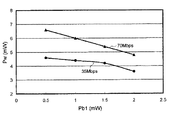
実施例1および実施例2の測定結果は、図6に示されている。 The measurement results of Example 1 and Example 2 are shown in FIG.
図6に示されるように、第1のパルス列パターンにしたがって、レーザビームのパワーを変調して、データを記録した場合には、第一の基底パワーPb1を高いレベルに設定するほど、レーザビームの最適記録パワーPwのレベルが低くなり、データ転送レートが約70Mbpsである場合に、レーザビームの最適記録パワーPwのレベルの低下が顕著であることが見出された。 As shown in FIG. 6, when data is recorded by modulating the power of the laser beam according to the first pulse train pattern, the higher the first base power Pb1 is set, the higher the level of the laser beam. It has been found that when the level of the optimum recording power Pw becomes low and the data transfer rate is about 70 Mbps, the level of the optimum recording power Pw of the laser beam is significantly reduced.
したがって、記録線速度が高く、データ転送レートが高い場合に、第1のパルス列パターンにしたがって、レーザビームのパワーを変調して、データを記録することが効果的であることがわかった。 Therefore, it has been found that when the recording linear velocity is high and the data transfer rate is high, it is effective to record data by modulating the power of the laser beam according to the first pulse train pattern.
また、記録線速度が高いほど、第一の基底パワーPb1を高いレベルに設定することによって、レーザビームの記録パワーPwを同じレベルあるいはほぼ同じレベルに保持しつつ、異なる記録線速度で、データを記録することが可能であることがわかった。すなわち、約35Mbpsのデータ転送レートで、データを記録する場合には、レーザビームの第一の基底パワーPb1および記録パワーPwを、それぞれ、0.5mWおよび4.6mWに設定し、約70Mbpsのデータ転送レートで、データを記録する場合には、レーザビームの第一の基底パワーPb1および記録パワーPwを、それぞれ、2.0mWおよび4.8mWに設定して、データを記録することによって、ジッターの悪化を防止することが可能になり、したがって、最高出力が5mWの比較的安価な半導体レーザを用いて、データを記録することができる。 Further, by setting the first base power Pb1 to a higher level as the recording linear velocity is higher, the data can be recorded at different recording linear velocities while maintaining the recording power Pw of the laser beam at the same level or substantially the same level. I found it possible to record. That is, when data is recorded at a data transfer rate of about 35 Mbps, the first base power Pb1 and the recording power Pw of the laser beam are set to 0.5 mW and 4.6 mW, respectively, and data of about 70 Mbps is set. When data is recorded at a transfer rate, jitter is reduced by recording the data by setting the first base power Pb1 and the recording power Pw of the laser beam to 2.0 mW and 4.8 mW, respectively. Deterioration can be prevented, and therefore data can be recorded using a relatively inexpensive semiconductor laser having a maximum output of 5 mW.
実施例3
第2のパルス列パターンにしたがって、レーザビームのパワーを変調した以外は、実施例1および実施例2と同様にして、光記録媒体にデータを記録し、ジッターが最小になったときのレーザビームの記録パワーPwを最適記録パワーPwとして決定し、レーザビームの最適記録パワーPwと、第一の基底パワーPb1との関係を求めた。
Example 3
Except that the power of the laser beam was modulated according to the second pulse train pattern, data was recorded on the optical recording medium in the same manner as in Example 1 and Example 2, and the laser beam when jitter was minimized The recording power Pw was determined as the optimum recording power Pw, and the relationship between the optimum recording power Pw of the laser beam and the first base power Pb1 was determined.
ここに、冷却期間Tclの長さは1Tとし、第二の基底パワーPb2は0.1mWに設定した。 Here, the length of the cooling period Tcl was 1T, and the second base power Pb2 was set to 0.1 mW.
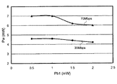
測定結果は、図7に示されている。 The measurement results are shown in FIG.
図7に示されるように、第2のパルス列パターンにしたがって、レーザビームのパワーを変調して、データを記録した場合においても、第一の基底パワーPb1を高いレベルに設定するほど、レーザビームの最適記録パワーPwのレベルが低くなり、データ転送レートが約70Mbpsである場合に、レーザビームの最適記録パワーPwのレベルの低下が顕著であることが見出された。 As shown in FIG. 7, even when data is recorded by modulating the power of the laser beam according to the second pulse train pattern, the higher the first base power Pb1 is set, the higher the level of the laser beam. It has been found that when the level of the optimum recording power Pw becomes low and the data transfer rate is about 70 Mbps, the level of the optimum recording power Pw of the laser beam is significantly reduced.
したがって、記録線速度が高く、データ転送レートが高い場合に、第2のパルス列パターンにしたがって、レーザビームのパワーを変調して、データを記録することが効果的であることがわかった。 Therefore, it has been found that when the recording linear velocity is high and the data transfer rate is high, it is effective to record data by modulating the power of the laser beam according to the second pulse train pattern.
また、第2のパルス列パターンにしたがって、レーザビームのパワーを変調して、データを記録した場合においても、記録線速度が高いほど、第一の基底パワーPb1を高いレベルに設定することによって、レーザビームの記録パワーPwをほぼ同じレベルに保持しつつ、異なる記録線速度で、データを記録することが可能であることがわかった。すなわち、約35Mbpsのデータ転送レートで、データを記録する場合には、レーザビームの第一の基底パワーPb1および記録パワーPwを、それぞれ、0.5mWおよび4.6mWに設定し、約70Mbpsのデータ転送レートで、データを記録する場合には、レーザビームの第一の基底パワーPb1および記録パワーPwを、それぞれ、2.0mWおよび6.0mWに設定して、データを記録することによって、ジッターの悪化を防止することが可能になり、したがって、最高出力が6mWの比較的安価な半導体レーザを用いて、データを記録することができる。 Even when data is recorded by modulating the power of the laser beam according to the second pulse train pattern, the laser beam is set by setting the first base power Pb1 to a higher level as the recording linear velocity is higher. It has been found that data can be recorded at different recording linear velocities while maintaining the beam recording power Pw at substantially the same level. That is, when data is recorded at a data transfer rate of about 35 Mbps, the first base power Pb1 and the recording power Pw of the laser beam are set to 0.5 mW and 4.6 mW, respectively, and data of about 70 Mbps is set. When data is recorded at a transfer rate, the first base power Pb1 and the recording power Pw of the laser beam are set to 2.0 mW and 6.0 mW, respectively. Deterioration can be prevented, and therefore data can be recorded using a relatively inexpensive semiconductor laser having a maximum output of 6 mW.
さらに、図6および図7に示されるように、第一の基底パワーPb1を高いレベルに設定するほど、レーザビームの最適記録パワーPwのレベルが低くなるという現象は、第2のパルス列パターンにしたがって、レーザビームのパワーを変調して、データを記録した場合よりも、第1のパルス列パターンにしたがって、レーザビームのパワーを変調して、データを記録した場合の方がより顕著になることが判明した。これは、第1のパルス列パターンは、第2のパルス列パターンとは異なり、冷却期間Tclを含んでいないため、第1の基底パワーPb1による加熱補助効果がより高かったためであると考えられる。 Further, as shown in FIGS. 6 and 7, the phenomenon that the level of the optimum recording power Pw of the laser beam becomes lower as the first base power Pb1 is set to a higher level is in accordance with the second pulse train pattern. It turns out that the data recorded by modulating the power of the laser beam according to the first pulse train pattern is more noticeable than the data recorded by modulating the power of the laser beam. did. This is probably because the first pulse train pattern, unlike the second pulse train pattern, does not include the cooling period Tcl, and thus the heating assist effect by the first base power Pb1 was higher.
実施例4
第1のパルス列パターンおよび第2のパルス列パターンを用いて、レーザビームのパワーを変調し、実施例1の記録条件にしたがって、光記録媒体にデータを記録し、光記録媒体に記録されたデータを再生して、第一の基底パワーPb1と、2T信号のC/N比の関係を測定した。
Example 4
The power of the laser beam is modulated using the first pulse train pattern and the second pulse train pattern, data is recorded on the optical recording medium according to the recording conditions of Example 1, and the data recorded on the optical recording medium is recorded. Reproduction was performed, and the relationship between the first base power Pb1 and the C / N ratio of the 2T signal was measured.
ここに、レーザビームの記録パワーPwとしては、ジッターが最小になったときのレーザビームの最適記録パワーPwを選択し、第2のパルス列パターンの冷却期間Tclの長さは1Tとし、第二の基底パワーPb2は0.1mWに設定した。 Here, as the recording power Pw of the laser beam, the optimum recording power Pw of the laser beam when the jitter is minimized is selected, the length of the cooling period Tcl of the second pulse train pattern is 1T, and the second The base power Pb2 was set to 0.1 mW.
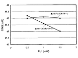
測定結果は、図8に示されている。 The measurement results are shown in FIG.
図8に示されるように、冷却期間Tclを含んでいない第1のパルス列パターンにしたがって、レーザビームのパワーを変調して、データを記録した場合には、第1の基底パワーPb1を増大させるにしたがって、2T信号のC/N比が低下することが認められたが、冷却期間Tclを含んでいる(いない)第2のパルス列パターンにしたがって、レーザビームのパワーを変調して、データを記録した場合には、第1の基底パワーPb1を増大させても、2T信号のC/N比の低下はほとんど認められなかった。 As shown in FIG. 8, when data is recorded by modulating the power of the laser beam in accordance with the first pulse train pattern not including the cooling period Tcl, the first base power Pb1 is increased. Therefore, it was recognized that the C / N ratio of the 2T signal was lowered, but data was recorded by modulating the power of the laser beam according to the second pulse train pattern including (not) the cooling period Tcl. In some cases, even when the first base power Pb1 was increased, the C / N ratio of the 2T signal was hardly decreased.
これは、第2のパルス列パターンにおいては、最後の分割パルスの直後に、レーザビームのパワーが、第2の基底パワーPb2となる冷却期間Tclが挿入されているので、記録マークを形成するために照射した記録パワーPwを有するレーザビームによって、加熱された記録マークの後縁部が効果的に冷却され、記録マークの後縁部よりもレーザビームの進行方向側の領域において、第一の記録層に主成分として含まれる元素と、第二の記録層に主成分として含まれる元素とが混合することが防止され、したがって、記録マークの後縁部がずれることが効果的に防止されて、記録マークの長さが所望の長さに制御されたためと考えられる。 In the second pulse train pattern, the cooling period Tcl in which the laser beam power becomes the second base power Pb2 is inserted immediately after the last divided pulse, so that a recording mark is formed. The trailing edge of the heated recording mark is effectively cooled by the irradiated laser beam having the recording power Pw, and the first recording layer is formed in a region closer to the laser beam traveling direction than the trailing edge of the recording mark. Is prevented from being mixed with the element contained as the main component in the second recording layer, and therefore, the trailing edge of the recording mark is effectively prevented from being shifted. This is probably because the mark length was controlled to a desired length.
本発明は、以上の実施態様および実施例に限定されることなく、特許請求の範囲に記載された発明の範囲内で種々の変更が可能であり、それらも本発明の範囲内に包含されるものであることはいうまでもない。 The present invention is not limited to the above embodiments and examples, and various modifications can be made within the scope of the invention described in the claims, and these are also included in the scope of the present invention. It goes without saying that it is a thing.
たとえば、前記実施態様および前記実施例においては、光記録媒体10の記録層14が、互いに接触するように形成された第一の反応層31と第二の反応層32とによって構成されているが、光記録媒体10の記録層14は、第一の反応層31と第二の反応層32を含んでいればよく、記録層14を、互いに接触するように形成された第一の反応層31と第二の反応層32とによって構成することは必ずしも必要でない。記録層14は、3層以上の反応層を備えていてもよく、たとえば、光記録媒体10の記録層14が、2つの第一の反応層31と、2つの第一の反応層31の間に配置された第二の反応層32とによって構成されていてもよい。
For example, in the embodiment and the example, the
また、前記実施態様および前記実施例においては、光記録媒体10は、第一の誘電体層15および第二の誘電体層13を備え、記録層14が、第一の誘電体層15および第二の誘電体層13の間に配置されているが、光記録媒体10が、第一の誘電体層15および第二の誘電体層13を備えていることは必ずしも必要でなく、単一の誘電体層を有していてもよいし、誘電体層を備えていなくてもよい。
In the embodiment and the example, the
さらに、前記実施態様および前記実施例においては、光記録媒体10は反射層12を備えているが、レーザ光が照射された結果、第一の反応層31に主成分として含まれた元素と、第二の反応層32に主成分として含まれた元素が混合して形成された記録マークMにおける反射光のレベルと、それ以外の領域における反射光のレベルの差が十分に大きい場合には、反射層12を省略することができる。
Furthermore, in the embodiment and the example, the
また、前記実施態様においては、第2のパルス列パターンを用いる場合に、第2のパルス列パターンにしたがって、レーザビームのパワーを変調して、すべての記録マークMを形成しているが、記録マークMの後縁部がずれて、記録マークMの長さが、所望の長さよりも長くなることを防止するために、レーザビームの記録パワーPwを低下させたときに、記録マークMの幅が細くなって、記録信号のC/N比(キャリア/ノイズ比)が顕著に低下するのは、記録マークMの長さが短い場合であるから、記録マークMの長さが最も短くなる2T信号を用いる場合だけに、第2のパルス列パターンにしたがって、レーザビームのパワーを変調するようにし、3T信号ないし8T信号を用いて、記録マークMを形成する場合には、第1のパルス列パターンにしたがって、レーザビームのパワーを変調するようにしてもよい。 In the above embodiment, when the second pulse train pattern is used, the power of the laser beam is modulated according to the second pulse train pattern to form all the recording marks M. When the recording power Pw of the laser beam is decreased, the width of the recording mark M is narrowed in order to prevent the trailing edge portion from being shifted and the length of the recording mark M from becoming longer than the desired length. Thus, the C / N ratio (carrier / noise ratio) of the recording signal is remarkably lowered when the length of the recording mark M is short. Therefore, the 2T signal in which the length of the recording mark M is the shortest is obtained. Only when it is used, the power of the laser beam is modulated according to the second pulse train pattern, and when the recording mark M is formed using the 3T signal to 8T signal, the first pulse train is used. Accordance turn, may be to modulate the power of the laser beam.
さらに、図5に示された実施態様においては、第1のパルス列パターンあるいは第2のパルス列パターンを特定するためのデータが、データを記録する際に必要な記録線速度などの種々の記録条件を特定するためのデータとともに、記録条件設定用データとして、ウォブルやプレピットの形で、光記録媒体10に記録されているが、第1のパルス列パターンあるいは第2のパルス列パターンを特定するためのデータを、データを記録する際に必要な記録線速度などの種々の記録条件を特定するためのデータとともに、記録条件設定用データを、ウォブルやプレピットの形で、光記録媒体10に記録しておくことは必ずしも必要でなく、光記録媒体10の第一の反応層31あるいは第二の反応層32に、記録条件設定用データを記録するようにしてもよい。
Further, in the embodiment shown in FIG. 5, the data for specifying the first pulse train pattern or the second pulse train pattern has various recording conditions such as a recording linear velocity necessary for recording the data. The data for specifying the first pulse train pattern or the second pulse train pattern is recorded on the
また、図5に示された実施態様においては、第1のパルス列パターンあるいは第2のパルス列パターンを特定するためのデータが、データを記録する際に必要な記録線速度などの種々の記録条件を特定するためのデータとともに、記録条件設定用データとして、光記録媒体10に、ウォブルやプレピットの形で、記録されているが、第1のパルス列パターンあるいは第2のパルス列パターンを特定するためのデータおよびデータを記録する際に必要な記録線速度などの種々の記録条件を特定するためのデータを、記録条件設定用データとして、光記録媒体10に記録しておくことは必ずしも必要でなく、第1のパルス列パターンあるいは第2のパルス列パターンを特定するためのデータのみが、記録条件設定用データとして、光記録媒体10に記録されていてもよい。
In the embodiment shown in FIG. 5, the data for specifying the first pulse train pattern or the second pulse train pattern has various recording conditions such as a recording linear velocity required for recording the data. Data for specifying the first pulse train pattern or the second pulse train pattern, which is recorded on the
さらに、図5に示された実施態様においては、第1のパルス列パターンあるいは第2のパルス列パターンを特定するためのデータが、データを記録する際に必要な記録線速度などの種々の記録条件を特定するためのデータとともに、記録条件設定用データとして、光記録媒体10に、ウォブルやプレピットの形で、記録されているが、第1のパルス列パターンあるいは第2のパルス列パターンを特定するためのデータおよびデータを記録する際に必要な記録線速度などの種々の記録条件を特定するためのデータを、記録条件設定用データとして、光記録媒体10に記録しておくことは必ずしも必要でなく、情報記録装置内に、第1のパルス列パターンあるいは第2のパルス列パターンを特定するためのデータおよび記録条件を特定するためのデータを、あらかじめ格納しておき、記録条件設定用データとして、それらに基づいて、情報記録装置内にあらかじめ格納されているデータを特定することができ、間接的に、選択すべき記録ストラテジを特定可能なデータを、光記録媒体10に記録しておくようにすることもできる。
Further, in the embodiment shown in FIG. 5, the data for specifying the first pulse train pattern or the second pulse train pattern has various recording conditions such as a recording linear velocity necessary for recording the data. Data for specifying the first pulse train pattern or the second pulse train pattern, which is recorded on the
また、図5に示された実施態様においては、フォーカスサーボ追従回路57、トラッキングサーボ追従回路58およびレーザコントロール回路59が、コントローラ54内に組み込まれているが、フォーカスサーボ追従回路57、トラッキングサーボ追従回路58およびレーザコントロール回路59を、コントローラ54内に組み込むことは必ずしも必要でなく、コントローラ54とは別体に、フォーカスサーボ追従回路57、トラッキングサーボ追従回路58およびレーザコントロール回路59を設けることもできるし、フォーカスサーボ追従回路57、トラッキングサーボ追従回路58およびレーザコントロール回路59の機能を果たすソフトウエアを、コントローラ54内に組み込むようにしてもよい。
In the embodiment shown in FIG. 5, the focus
さらに、前記実施態様および前記実施例においては、高出力の半導体レーザを用いることが要求される次世代型の光記録媒体にデータを記録する場合につき、説明を加えたが、本発明は、次世代型の光記録媒体にデータを記録する場合に限らず、次世代型の光記録媒体以外の追記型光記録媒体に、データを記録する場合に広く適用することができる。 Further, in the embodiment and the example described above, the case where data is recorded on a next-generation optical recording medium that requires the use of a high-power semiconductor laser has been described. The present invention is not limited to the case of recording data on a generation type optical recording medium, but can be widely applied to the case of recording data on a write-once type optical recording medium other than the next generation type optical recording medium.
10 光記録媒体
11 基板
11a ランド
11b グルーブ
12 反射層
13 第二の誘電体層
14 記録層
15 第一の誘電体層
16 光透過層
17 センターホール
31 第一の反応層
32 第二の反応層
50 情報記録装置
52 スピンドルモータ
53 ヘッド
54 コントローラ
55 レーザ駆動回路
56 レンズ駆動回路
57 フォーカスサーボ追従回路
58 トラッキングサーボ追従回路
59 レーザコントロール回路
L10 レーザビーム
M 記録マーク(混合領域)
10 optical recording medium 11 substrate 11a
Claims (20)
Priority Applications (1)
| Application Number | Priority Date | Filing Date | Title |
|---|---|---|---|
| JP2005155793A JP2005293843A (en) | 2005-05-27 | 2005-05-27 | Method for recording information to optical recording medium, device for recording information to optical recording medium, and optical recording medium |
Applications Claiming Priority (1)
| Application Number | Priority Date | Filing Date | Title |
|---|---|---|---|
| JP2005155793A JP2005293843A (en) | 2005-05-27 | 2005-05-27 | Method for recording information to optical recording medium, device for recording information to optical recording medium, and optical recording medium |
Related Parent Applications (1)
| Application Number | Title | Priority Date | Filing Date |
|---|---|---|---|
| JP2002143477A Division JP2003338038A (en) | 2002-05-17 | 2002-05-17 | Method and apparatus for recording information on optical recording medium, and optical recording medium |
Publications (1)
| Publication Number | Publication Date |
|---|---|
| JP2005293843A true JP2005293843A (en) | 2005-10-20 |
Family
ID=35326569
Family Applications (1)
| Application Number | Title | Priority Date | Filing Date |
|---|---|---|---|
| JP2005155793A Pending JP2005293843A (en) | 2005-05-27 | 2005-05-27 | Method for recording information to optical recording medium, device for recording information to optical recording medium, and optical recording medium |
Country Status (1)
| Country | Link |
|---|---|
| JP (1) | JP2005293843A (en) |
-
2005
- 2005-05-27 JP JP2005155793A patent/JP2005293843A/en active Pending
Similar Documents
| Publication | Publication Date | Title |
|---|---|---|
| JP3868406B2 (en) | Method for recording data on optical recording medium and apparatus for recording data on optical recording medium | |
| US7254101B2 (en) | Laser beam power modulation pattern decision method, device for recording data onto optical recording medium, and optical recording medium | |
| EP1418574A2 (en) | Information recording apparatus and information recording method | |
| KR100716044B1 (en) | Method of recording data on optical recording medium, apparatus for recording data on optical recording medium and optical recording medium | |
| JP3868455B2 (en) | Information recording method for optical recording medium, information recording apparatus for optical recording medium, and optical recording medium | |
| JP2004047053A (en) | Method and device for recording data on optical recording medium and optical recording medium | |
| US7554892B2 (en) | Method for recording data in optical recording medium, an apparatus for recording data in optical recording medium and optical recording medium | |
| JP3954621B2 (en) | Information recording method for optical recording medium, information recording apparatus for optical recording medium, and optical recording medium | |
| JP4249102B2 (en) | Method for recording data on optical recording medium and apparatus for recording data on optical recording medium | |
| JP2005293843A (en) | Method for recording information to optical recording medium, device for recording information to optical recording medium, and optical recording medium | |
| US7443775B2 (en) | Method for recording data in optical recording medium, and apparatus for recording data in optical recording medium and optical recording medium | |
| JP2005071516A (en) | Data recording method for optical recording disk, and data recording apparatus for optical recording disk | |
| CN1942937B (en) | Optical recording method and recording apparatus | |
| JP2005293845A (en) | Method for recording information to optical recording medium, device for recording information to optical recording medium, and optical recording medium | |
| US20060280111A1 (en) | Optical storage medium and optical recording method | |
| JP2005004949A (en) | Information recording method, information recording apparatus, and information recording medium | |
| JP2004158167A (en) | Optical recording medium and method for recording data to optical recording medium | |
| JP2006018982A (en) | Recording method and recording apparatus for phase change information recording medium | |
| JP2005004800A (en) | Information recording method, information recording apparatus, and information recording medium | |
| JP2003136840A (en) | Optical information recording medium | |
| JP2005018829A (en) | Recording / reproducing method of phase change type optical information recording medium |
Legal Events
| Date | Code | Title | Description |
|---|---|---|---|
| A131 | Notification of reasons for refusal |
Free format text: JAPANESE INTERMEDIATE CODE: A131 Effective date: 20050809 |
|
| A521 | Written amendment |
Free format text: JAPANESE INTERMEDIATE CODE: A523 Effective date: 20051007 |
|
| A02 | Decision of refusal |
Free format text: JAPANESE INTERMEDIATE CODE: A02 Effective date: 20061003 |
|
| A521 | Written amendment |
Free format text: JAPANESE INTERMEDIATE CODE: A523 Effective date: 20061129 |
|
| A521 | Written amendment |
Free format text: JAPANESE INTERMEDIATE CODE: A821 Effective date: 20061102 |
|
| A911 | Transfer of reconsideration by examiner before appeal (zenchi) |
Free format text: JAPANESE INTERMEDIATE CODE: A911 Effective date: 20061220 |
|
| A912 | Removal of reconsideration by examiner before appeal (zenchi) |
Free format text: JAPANESE INTERMEDIATE CODE: A912 Effective date: 20070330 |