EP1510977A1 - Vorrichtung zur Erkennung der Schräglage eines Dokuments - Google Patents
Vorrichtung zur Erkennung der Schräglage eines Dokuments Download PDFInfo
- Publication number
- EP1510977A1 EP1510977A1 EP04019795A EP04019795A EP1510977A1 EP 1510977 A1 EP1510977 A1 EP 1510977A1 EP 04019795 A EP04019795 A EP 04019795A EP 04019795 A EP04019795 A EP 04019795A EP 1510977 A1 EP1510977 A1 EP 1510977A1
- Authority
- EP
- European Patent Office
- Prior art keywords
- optical
- note
- path
- light
- detector
- Prior art date
- Legal status (The legal status is an assumption and is not a legal conclusion. Google has not performed a legal analysis and makes no representation as to the accuracy of the status listed.)
- Granted
Links
Images

Classifications
-
- G—PHYSICS
- G07—CHECKING-DEVICES
- G07D—HANDLING OF COINS OR VALUABLE PAPERS, e.g. TESTING, SORTING BY DENOMINATIONS, COUNTING, DISPENSING, CHANGING OR DEPOSITING
- G07D7/00—Testing specially adapted to determine the identity or genuineness of valuable papers or for segregating those which are unacceptable, e.g. banknotes that are alien to a currency
- G07D7/17—Apparatus characterised by positioning means or by means responsive to positioning
-
- G—PHYSICS
- G07—CHECKING-DEVICES
- G07D—HANDLING OF COINS OR VALUABLE PAPERS, e.g. TESTING, SORTING BY DENOMINATIONS, COUNTING, DISPENSING, CHANGING OR DEPOSITING
- G07D11/00—Devices accepting coins; Devices accepting, dispensing, sorting or counting valuable papers
- G07D11/10—Mechanical details
- G07D11/16—Handling of valuable papers
- G07D11/17—Aligning
Definitions
- the present invention relates generally to a note skew detector.
- a detector in accordance with the present invention has application, for example, to the detection of skewed bank noted in the transport path of an Automated Teller Machine (ATM).
- ATM Automated Teller Machine
- Notes can become skewed as they are transported from a note storage cassette to the output slot of the ATM, as can notes deposited by a user and it is equally important to detect skew in notes being deposited in the ATM.
- a variety of different prior art detectors have been utilized to detect note skew in ATMs. These include both electromechanical and optical detectors. However, they all have certain features in common. In particular, they all rely on a pair of sensors, each of which is located at a predetermined position along the transport path within the ATM. Also as the detector is arranged to determine skew perpendicular to the direction of travel along the transport path, both the sensors and light sources must be located within the transport path, thus making assembly and serviceability of the detectors difficult. For example, cables must be laid into both sides of the transport path to connect to the sensors.
- a note skew detector for use in a note transport mechanism, the detector comprising a light source and an optical sensor, which are optically coupled via two distinct optical paths which are formed in part by optical light guides.
- the optical sensor is a single optical sensor and the light-guides are optical wave-guides.
- the detector further comprises a control means arranged to make determinations as to the degree of skew of a note based on the signal produced from the sensor.
- the detector when in use, is arranged such that the sensor receives light via each optical path, the output of the sensor being dependent on whether or not a note is present in either or both optical paths.
- a note skew detector for use in a note transport mechanism of an Automated Teller Machine (ATM) the detector comprising a light source and a single optical sensor, optically coupled via two pairs of optical wave-guides each pair being arranged to have an air gap there between so as to provide a note transport path between the said wave-guides, the wave-guide pairs being further arranged to provide a first optical path and a second, distinct, optical path between said light source and said sensor.
- ATM Automated Teller Machine
- a method of detecting skew in a bank note being transported along the transport path of a note transport mechanism, utilizing a note skew detector comprising a light source and an optical sensor, which are optically coupled via light guides arranged to transmit light from the source to the sensor via two distinct optical paths, the method comprising detecting an output at the sensor based on light transmitted via both the first and second optical paths.
- an Automated Teller Machine having a note skew detector as described above, wherein the light source and sensor are located outside of the note transport path of the ATM.
- Fig. 1 illustrates a skew note detector 10, including an optical sensing means 12, for use in a note transport mechanism 14 of an Automated teller Machine (ATM) (not shown).
- the detector 10 comprises a light source 16 and a single optical sensor 18, optically coupled via a pair of optical wave-guides 20A, 20B.
- the wave-guides are arranged to have an air gap 22 there between, so as to provide a note transport path between the said wave-guides.
- the wave-guides are further arranged to provide a first optical path 24A and a second, distinct, optical path 24B between the light source 16 and the sensor 18.
- the output of the sensor 18 is dependent on the light transmitted via the wave-guides 20A, 20B to the sensor 18, over both optical paths 24A, 24B.
- the output of the sensor 18 is fed to a control means 25 arranged to make determinations as to the degree of skew of a note based on the output of the sensor 18, as will be discussed in more detail below, with reference to Figs. 2 & 3.
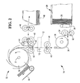
- Fig. 2 illustrates the use of the detector 10 in the transport mechanism 14. In addition it illustrates the flexibility of the detector which, in addition to note skew detection can also provide information on double picked notes.
- the cash transport mechanism of Fig. 2 is part of an ATM cash dispensing mechanism, comprising a currency cassette 26 arranged to contain a stack of currency notes 28 of the same pre-determined denomination supported on their long edges.
- the cassette 26 is associated with a pick mechanism 30.
- the pick mechanism 30 draws out notes one by one from the stack 28, and each note is fed by feed rollers 32,34,36 via guide means 38 to feed rollers 40.
- the direction of feed of the notes is at right angles to their long dimensions.
- the cash dispensing mechanism 14 could include more than one cassette each associated with a pick mechanism, but in the present embodiment only one cassette and pick mechanism will be described.
- Each picked note is passed through the sensing station 12 by the feed rollers 40 and by further feed rollers 42. If a multiple note is detected by the optical system 10, in a manner to be described in more detail below, then a divert gate 44 diverts the multiple note via rollers 46 into a reject bin 48, in a manner known to a skilled person.
- the stacking wheel 50 comprises a plurality of stacking plates 52 spaced apart in parallel relationship along the shaft 51 of the stacking wheel 50.
- the belt means 56 transports the notes to a cash delivery slot (not shown), again in a manner known to a skilled person, which will not therefore be described further herein.
- the detector 10 is positioned within the transport mechanism 14, such that the first and second wave-guides 20A, 20B lie on opposite sides of the transport path. Thus one or more bank notes being transported by the mechanism will pass through the air gap 22 between the wave-guides 20A, 20B.
- the source 16 and sensor 18 are arranged at the same side of the transport path all necessary wiring can be located at the one side making assembly and repair considerably easier than in prior art detectors. Hence there is no need to feed wiring into the body of the transport mechanism, as with prior art skew and double pick detectors.
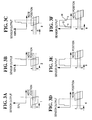
- Figs. 3A to 3F illustrate, the output of the sensor 18 as a skewed note passes through the air gap 22 in the detector 10.
- a reader may find it more intuitive for the blocking of one optical path (by a bank note) to result in a 50% reduction in the signal from the sensor, as 50% of the light is being blocked.
- a 50% increase is read here only due to an inversion at the detector, as selected by the inventors.
- the signals illustrated in Figs. 3A to 3F could be inverted and the system would still function normally.
- Fig. 3B the note has moved forward and now covers beam position A as well as position B resulting in a 100% sensor output signal.
- the interval between the two positions seen as a flat horizontal line in Fig. 3B, is representative of the skew of the note. The longer the flat horizontal line the greater the note skew.
- Fig. 3C the skewed note proceeds until, as seen in Fig. 3.D, the trailing edge of the note passes out of the optical path of the detector at point A. At this point, as seen in Fig. 3D, the sensor output again falls to 50%.
- Fig. 3E illustrates the 50% output from the sensor because once again only one optical path (that at A) is blocked by the note, until that portion of the note also passes out of the optical path and the output falls to 0, as seen in Fig. 3F.
- the skewed note has left the beam A.
- the skew detected at the leading edge and the trailing edge can now be compared for enhanced note information.
- the flat lines at 50% intensity at the beginning and the end of Fig. 3F can be measured to determine the degree of skew.
- the distances from X to Y and G to H can each be measured to determine the width of the note.
Landscapes
- Physics & Mathematics (AREA)
- General Physics & Mathematics (AREA)
- Controlling Sheets Or Webs (AREA)
Applications Claiming Priority (2)
| Application Number | Priority Date | Filing Date | Title |
|---|---|---|---|
| GBGB0319882.7A GB0319882D0 (en) | 2003-08-23 | 2003-08-23 | A note skew detector |
| GB0319882 | 2003-08-23 |
Publications (2)
| Publication Number | Publication Date |
|---|---|
| EP1510977A1 true EP1510977A1 (de) | 2005-03-02 |
| EP1510977B1 EP1510977B1 (de) | 2008-02-13 |
Family
ID=28460220
Family Applications (1)
| Application Number | Title | Priority Date | Filing Date |
|---|---|---|---|
| EP04019795A Expired - Lifetime EP1510977B1 (de) | 2003-08-23 | 2004-08-20 | Vorrichtung zur Erkennung der Schräglage eines Dokuments |
Country Status (5)
| Country | Link |
|---|---|
| US (1) | US7242486B2 (de) |
| EP (1) | EP1510977B1 (de) |
| DE (1) | DE602004011709T2 (de) |
| ES (1) | ES2298655T3 (de) |
| GB (1) | GB0319882D0 (de) |
Cited By (1)
| Publication number | Priority date | Publication date | Assignee | Title |
|---|---|---|---|---|
| EP1895481A3 (de) * | 2006-08-10 | 2008-12-17 | Sanden Corporation | Banknotenprüfgerät |
Families Citing this family (2)
| Publication number | Priority date | Publication date | Assignee | Title |
|---|---|---|---|---|
| US7721952B2 (en) * | 2007-08-02 | 2010-05-25 | Ncr Corporation | Presenting misaligned stacks of media |
| EP2680238A4 (de) * | 2011-02-22 | 2015-04-08 | Glory Kogyo Kk | Geldverarbeitungsvorrichtung, geldverarbeitungssystem, geldzufuhrkassette, papiergeldverarbeitungsvorrichtung und papiergeldverarbeitungsverfahren |
Citations (3)
| Publication number | Priority date | Publication date | Assignee | Title |
|---|---|---|---|---|
| US4559451A (en) * | 1981-11-13 | 1985-12-17 | De La Rue Systems Limited | Apparatus for determining with high resolution the position of edges of a web |
| EP0881604A1 (de) * | 1997-05-30 | 1998-12-02 | Sanden Corporation | Bankautomat mit Schrägheitsprüfung |
| EP1248224A2 (de) * | 2001-03-19 | 2002-10-09 | De La Rue International Limited | Blatterkennungs-Anordnung und -Verfahren |
Family Cites Families (10)
| Publication number | Priority date | Publication date | Assignee | Title |
|---|---|---|---|---|
| US4106667A (en) * | 1976-12-20 | 1978-08-15 | International Business Machines Corporation | Apparatus and method for conducting financial transactions |
| JPS5622903A (en) | 1979-08-01 | 1981-03-04 | Kanai Hiroyuki | Measuring instrument for web unevenness |
| JPS62159007A (ja) | 1986-01-07 | 1987-07-15 | Mitsubishi Heavy Ind Ltd | 製函機用段ボ−ル紙片姿勢検出装置 |
| JPH0989538A (ja) | 1995-09-21 | 1997-04-04 | Oki Electric Ind Co Ltd | 光学センサ装置 |
| US6241244B1 (en) * | 1997-11-28 | 2001-06-05 | Diebold, Incorporated | Document sensor for currency recycling automated banking machine |
| US6913260B2 (en) * | 2002-03-06 | 2005-07-05 | Cummins-Allison Corp. | Currency processing system with fitness detection |
| ATE396942T1 (de) * | 2003-03-12 | 2008-06-15 | Rue De Int Ltd | Optische doppelzufuhrerfassung |
| GB0319884D0 (en) * | 2003-08-23 | 2003-09-24 | Ncr Int Inc | An optical sensor and method of operation thereof |
| GB2405464A (en) * | 2003-08-23 | 2005-03-02 | Ncr Int Inc | Optical bank note detector |
| KR100644703B1 (ko) * | 2005-06-28 | 2006-11-10 | 삼성전자주식회사 | 용지검출장치 및 인쇄방법 |
-
2003
- 2003-08-23 GB GBGB0319882.7A patent/GB0319882D0/en not_active Ceased
-
2004
- 2004-08-20 EP EP04019795A patent/EP1510977B1/de not_active Expired - Lifetime
- 2004-08-20 ES ES04019795T patent/ES2298655T3/es not_active Expired - Lifetime
- 2004-08-20 DE DE602004011709T patent/DE602004011709T2/de not_active Expired - Lifetime
- 2004-08-20 US US10/922,524 patent/US7242486B2/en not_active Expired - Lifetime
Patent Citations (3)
| Publication number | Priority date | Publication date | Assignee | Title |
|---|---|---|---|---|
| US4559451A (en) * | 1981-11-13 | 1985-12-17 | De La Rue Systems Limited | Apparatus for determining with high resolution the position of edges of a web |
| EP0881604A1 (de) * | 1997-05-30 | 1998-12-02 | Sanden Corporation | Bankautomat mit Schrägheitsprüfung |
| EP1248224A2 (de) * | 2001-03-19 | 2002-10-09 | De La Rue International Limited | Blatterkennungs-Anordnung und -Verfahren |
Cited By (1)
| Publication number | Priority date | Publication date | Assignee | Title |
|---|---|---|---|---|
| EP1895481A3 (de) * | 2006-08-10 | 2008-12-17 | Sanden Corporation | Banknotenprüfgerät |
Also Published As
| Publication number | Publication date |
|---|---|
| GB0319882D0 (en) | 2003-09-24 |
| EP1510977B1 (de) | 2008-02-13 |
| DE602004011709D1 (de) | 2008-03-27 |
| DE602004011709T2 (de) | 2009-01-15 |
| ES2298655T3 (es) | 2008-05-16 |
| US7242486B2 (en) | 2007-07-10 |
| US20050041240A1 (en) | 2005-02-24 |
Similar Documents
| Publication | Publication Date | Title |
|---|---|---|
| KR20080094426A (ko) | 초음파를 이용한 테이프권 검출장치 및 그 방법 | |
| JP5268667B2 (ja) | 紙幣処理機 | |
| JP6876616B2 (ja) | 紙葉類処理装置、及び紙葉類処理方法 | |
| KR101169454B1 (ko) | 지폐 처리 기계 | |
| JP2006350820A (ja) | 紙葉類識別装置 | |
| US7242486B2 (en) | Note skew detector | |
| KR100961576B1 (ko) | 종이매체 공급장치 및 그 제어 방법 | |
| EP2743894B1 (de) | Gefälschte Medienerkennung | |
| KR102294704B1 (ko) | 지폐 계수기의 지폐집적장치 | |
| US7194151B2 (en) | Optical media detector and method of operation thereof | |
| KR101871439B1 (ko) | 매체 이송 처리 장치 및 방법과 그의 금융기기 | |
| JP5286794B2 (ja) | 紙幣処理装置 | |
| JP4608814B2 (ja) | 媒体処理装置 | |
| CN108629890A (zh) | 用于对齐至少一个有价票据的布置结构和方法 | |
| KR101413954B1 (ko) | 매체 감지 장치 및 금융기기 | |
| JPH02249837A (ja) | 紙葉類のスキュー検知装置 | |
| JP2587126B2 (ja) | 紙葉類認識装置 | |
| JP4674065B2 (ja) | 媒体識別装置及び媒体処理装置 | |
| JP2004185447A (ja) | 紙幣識別装置及び紙幣処理装置 | |
| KR20250018322A (ko) | 금융 자동화 기기 및 금융 자동화 기기 제어방법 | |
| JPH06206647A (ja) | 搬送装置 | |
| WO2002082385A1 (en) | A detector arrangement for use in conjunction with document transporting means | |
| HK1150210B (en) | Bill processing machine | |
| HK1145367B (en) | Bill processing machine | |
| JPH0797085A (ja) | 紙葉類繰出し調整機構 |
Legal Events
| Date | Code | Title | Description |
|---|---|---|---|
| PUAI | Public reference made under article 153(3) epc to a published international application that has entered the european phase |
Free format text: ORIGINAL CODE: 0009012 |
|
| AK | Designated contracting states |
Kind code of ref document: A1 Designated state(s): AT BE BG CH CY CZ DE DK EE ES FI FR GB GR HU IE IT LI LU MC NL PL PT RO SE SI SK TR |
|
| AX | Request for extension of the european patent |
Extension state: AL HR LT LV MK |
|
| 17P | Request for examination filed |
Effective date: 20050902 |
|
| AKX | Designation fees paid |
Designated state(s): DE ES FR GB IT |
|
| 17Q | First examination report despatched |
Effective date: 20061006 |
|
| GRAP | Despatch of communication of intention to grant a patent |
Free format text: ORIGINAL CODE: EPIDOSNIGR1 |
|
| GRAS | Grant fee paid |
Free format text: ORIGINAL CODE: EPIDOSNIGR3 |
|
| GRAA | (expected) grant |
Free format text: ORIGINAL CODE: 0009210 |
|
| AK | Designated contracting states |
Kind code of ref document: B1 Designated state(s): DE ES FR GB IT |
|
| REG | Reference to a national code |
Ref country code: GB Ref legal event code: FG4D |
|
| REF | Corresponds to: |
Ref document number: 602004011709 Country of ref document: DE Date of ref document: 20080327 Kind code of ref document: P |
|
| REG | Reference to a national code |
Ref country code: DE Ref legal event code: R096 Ref document number: 602004011709 Country of ref document: DE Effective date: 20080327 |
|
| REG | Reference to a national code |
Ref country code: ES Ref legal event code: FG2A Ref document number: 2298655 Country of ref document: ES Kind code of ref document: T3 |
|
| ET | Fr: translation filed | ||
| REG | Reference to a national code |
Ref country code: GB Ref legal event code: 746 Effective date: 20080919 |
|
| REG | Reference to a national code |
Ref country code: DE Ref legal event code: R084 Ref document number: 602004011709 Country of ref document: DE Effective date: 20080818 |
|
| PLBE | No opposition filed within time limit |
Free format text: ORIGINAL CODE: 0009261 |
|
| STAA | Information on the status of an ep patent application or granted ep patent |
Free format text: STATUS: NO OPPOSITION FILED WITHIN TIME LIMIT |
|
| 26N | No opposition filed |
Effective date: 20081114 |
|
| REG | Reference to a national code |
Ref country code: DE Ref legal event code: R097 Ref document number: 602004011709 Country of ref document: DE Effective date: 20081114 |
|
| PG25 | Lapsed in a contracting state [announced via postgrant information from national office to epo] |
Ref country code: IT Free format text: LAPSE BECAUSE OF NON-PAYMENT OF DUE FEES Effective date: 20100820 |
|
| REG | Reference to a national code |
Ref country code: FR Ref legal event code: PLFP Year of fee payment: 13 |
|
| REG | Reference to a national code |
Ref country code: FR Ref legal event code: PLFP Year of fee payment: 14 |
|
| REG | Reference to a national code |
Ref country code: FR Ref legal event code: PLFP Year of fee payment: 15 |
|
| P01 | Opt-out of the competence of the unified patent court (upc) registered |
Effective date: 20230512 |
|
| PGFP | Annual fee paid to national office [announced via postgrant information from national office to epo] |
Ref country code: IT Payment date: 20230822 Year of fee payment: 20 Ref country code: GB Payment date: 20230828 Year of fee payment: 20 Ref country code: ES Payment date: 20230901 Year of fee payment: 20 |
|
| PGFP | Annual fee paid to national office [announced via postgrant information from national office to epo] |
Ref country code: FR Payment date: 20230825 Year of fee payment: 20 Ref country code: DE Payment date: 20230829 Year of fee payment: 20 |
|
| REG | Reference to a national code |
Ref country code: DE Ref legal event code: R071 Ref document number: 602004011709 Country of ref document: DE |
|
| REG | Reference to a national code |
Ref country code: ES Ref legal event code: FD2A Effective date: 20240827 |
|
| REG | Reference to a national code |
Ref country code: GB Ref legal event code: PE20 Expiry date: 20240819 |
|
| PG25 | Lapsed in a contracting state [announced via postgrant information from national office to epo] |
Ref country code: GB Free format text: LAPSE BECAUSE OF EXPIRATION OF PROTECTION Effective date: 20240819 |
|
| PG25 | Lapsed in a contracting state [announced via postgrant information from national office to epo] |
Ref country code: ES Free format text: LAPSE BECAUSE OF EXPIRATION OF PROTECTION Effective date: 20240821 |
|
| PG25 | Lapsed in a contracting state [announced via postgrant information from national office to epo] |
Ref country code: GB Free format text: LAPSE BECAUSE OF EXPIRATION OF PROTECTION Effective date: 20240819 Ref country code: ES Free format text: LAPSE BECAUSE OF EXPIRATION OF PROTECTION Effective date: 20240821 |