EP1510965A1 - Kartenadapter - Google Patents
Kartenadapter Download PDFInfo
- Publication number
- EP1510965A1 EP1510965A1 EP03730756A EP03730756A EP1510965A1 EP 1510965 A1 EP1510965 A1 EP 1510965A1 EP 03730756 A EP03730756 A EP 03730756A EP 03730756 A EP03730756 A EP 03730756A EP 1510965 A1 EP1510965 A1 EP 1510965A1
- Authority
- EP
- European Patent Office
- Prior art keywords
- card
- connector
- board
- compliant
- circuit board
- Prior art date
- Legal status (The legal status is an assumption and is not a legal conclusion. Google has not performed a legal analysis and makes no representation as to the accuracy of the status listed.)
- Withdrawn
Links
Images


Classifications
-
- G—PHYSICS
- G06—COMPUTING; CALCULATING OR COUNTING
- G06K—GRAPHICAL DATA READING; PRESENTATION OF DATA; RECORD CARRIERS; HANDLING RECORD CARRIERS
- G06K19/00—Record carriers for use with machines and with at least a part designed to carry digital markings
- G06K19/005—Record carriers for use with machines and with at least a part designed to carry digital markings the record carrier comprising an arrangement to facilitate insertion into a holding device, e.g. an arrangement that makes the record carrier fit into an etui or a casing
-
- G—PHYSICS
- G06—COMPUTING; CALCULATING OR COUNTING
- G06K—GRAPHICAL DATA READING; PRESENTATION OF DATA; RECORD CARRIERS; HANDLING RECORD CARRIERS
- G06K19/00—Record carriers for use with machines and with at least a part designed to carry digital markings
- G06K19/06—Record carriers for use with machines and with at least a part designed to carry digital markings characterised by the kind of the digital marking, e.g. shape, nature, code
- G06K19/067—Record carriers with conductive marks, printed circuits or semiconductor circuit elements, e.g. credit or identity cards also with resonating or responding marks without active components
- G06K19/07—Record carriers with conductive marks, printed circuits or semiconductor circuit elements, e.g. credit or identity cards also with resonating or responding marks without active components with integrated circuit chips
- G06K19/077—Constructional details, e.g. mounting of circuits in the carrier
- G06K19/07737—Constructional details, e.g. mounting of circuits in the carrier the record carrier consisting of two or more mechanically separable parts
- G06K19/07741—Constructional details, e.g. mounting of circuits in the carrier the record carrier consisting of two or more mechanically separable parts comprising a first part operating as a regular record carrier and a second attachable part that changes the functional appearance of said record carrier, e.g. a contact-based smart card with an adapter part which, when attached to the contact card makes the contact card function as a non-contact card
-
- G—PHYSICS
- G06—COMPUTING; CALCULATING OR COUNTING
- G06K—GRAPHICAL DATA READING; PRESENTATION OF DATA; RECORD CARRIERS; HANDLING RECORD CARRIERS
- G06K7/00—Methods or arrangements for sensing record carriers, e.g. for reading patterns
- G06K7/0013—Methods or arrangements for sensing record carriers, e.g. for reading patterns by galvanic contacts, e.g. card connectors for ISO-7816 compliant smart cards or memory cards, e.g. SD card readers
- G06K7/0021—Methods or arrangements for sensing record carriers, e.g. for reading patterns by galvanic contacts, e.g. card connectors for ISO-7816 compliant smart cards or memory cards, e.g. SD card readers for reading/sensing record carriers having surface contacts
-
- G—PHYSICS
- G06—COMPUTING; CALCULATING OR COUNTING
- G06K—GRAPHICAL DATA READING; PRESENTATION OF DATA; RECORD CARRIERS; HANDLING RECORD CARRIERS
- G06K7/00—Methods or arrangements for sensing record carriers, e.g. for reading patterns
- G06K7/0013—Methods or arrangements for sensing record carriers, e.g. for reading patterns by galvanic contacts, e.g. card connectors for ISO-7816 compliant smart cards or memory cards, e.g. SD card readers
- G06K7/0047—Methods or arrangements for sensing record carriers, e.g. for reading patterns by galvanic contacts, e.g. card connectors for ISO-7816 compliant smart cards or memory cards, e.g. SD card readers for reading/sensing record carriers having edge contacts
-
- G—PHYSICS
- G06—COMPUTING; CALCULATING OR COUNTING
- G06K—GRAPHICAL DATA READING; PRESENTATION OF DATA; RECORD CARRIERS; HANDLING RECORD CARRIERS
- G06K7/00—Methods or arrangements for sensing record carriers, e.g. for reading patterns
- G06K7/0013—Methods or arrangements for sensing record carriers, e.g. for reading patterns by galvanic contacts, e.g. card connectors for ISO-7816 compliant smart cards or memory cards, e.g. SD card readers
- G06K7/0056—Methods or arrangements for sensing record carriers, e.g. for reading patterns by galvanic contacts, e.g. card connectors for ISO-7816 compliant smart cards or memory cards, e.g. SD card readers housing of the card connector
- G06K7/006—Methods or arrangements for sensing record carriers, e.g. for reading patterns by galvanic contacts, e.g. card connectors for ISO-7816 compliant smart cards or memory cards, e.g. SD card readers housing of the card connector the housing being a portable casing
-
- H—ELECTRICITY
- H05—ELECTRIC TECHNIQUES NOT OTHERWISE PROVIDED FOR
- H05K—PRINTED CIRCUITS; CASINGS OR CONSTRUCTIONAL DETAILS OF ELECTRIC APPARATUS; MANUFACTURE OF ASSEMBLAGES OF ELECTRICAL COMPONENTS
- H05K1/00—Printed circuits
- H05K1/18—Printed circuits structurally associated with non-printed electric components
- H05K1/189—Printed circuits structurally associated with non-printed electric components characterised by the use of a flexible or folded printed circuit
Definitions
- the present invention relates to a card adapter to connect a removable compact memory card to portable information equipments represented by PC (personal computer), PDA (personal digital assistants), digital still camera or the like.
- PC personal computer
- PDA personal digital assistants
- digital still camera or the like.
- Recent notebook computers are generally provided with PC card slots.
- the PC card inserted in the slot can extend functionalities of the notebook computers.
- the PC card satisfies the PC Card Standard with a flat rectangular shape of 54.0 mm wide, 85.6 mm long, and 3.3 mm (type I), 5.0 mm (type II) and 10.5 mm (type III) high respectively.
- PC Card Standard with a flat rectangular shape of 54.0 mm wide, 85.6 mm long, and 3.3 mm (type I), 5.0 mm (type II) and 10.5 mm (type III) high respectively.
- a CF card that is more compact in size has been introduced in many cases.
- the CF card represented by the Flash memory card is used to store images taken by digital still cameras or schedule and address data in PDAs.
- the CF card compliant with the CompactFlash Association Standard (hereafter referred to as the first specification) has a flat rectangular shape of 36.4 mm wide, 42.5 mm long, and 3.3 mm (type I) and 5.0 mm (type II) high respectively.
- Most recent PDAs and digital cameras adopt 3.3 mm high model (type I) being advantageous for product downsizing.
- compact memory cards specialized in memory have been used widely for digital still cameras, silicon-audio players or the like as a storage media.
- These compact memory cards having memory IC chips or controller IC chips and directly packaged using resin have a feature of extremely low profile.
- Smart media cards and MMCs MultiMedia Cards
- MMCs MultiMedia Cards
- the SD memory card Secure Digital memory card
- copyright protection functions has become very popular recently with its compact size, large capacity and high transfer rate.
- standard for these compact memory cards is referred to generically as the second specification.
- a CF-card-shaped card adapter provided with a signal processing circuit to convert data between both specifications is necessary.
- conventional CF-card-shaped card adapter has slot connectors mounted on the top surface of an internal circuit board to form a holder for a compact memory card.
- the signal processing circuit is formed to convert signals between both specifications. Therefore, the thickness of the card adapter can be the minimum when followings are stacked with no space in between: a holder for a compact memory card or a slot connector; a circuit board; parts for the signal processing circuit; and metal covers to cover top and bottom surfaces of the card adapter.
- a card adapter to allow a card adapter to connect to information equipment having CF type I slot, a card adapter has been realized complying the width and thickness of the card adapter with respect to the insertion direction with CF type I and extending the longitudinal length along the insertion direction longer than CF type I.
- CF type I card adapter As conventional compact memory cards have thicknesses approximately equal to the thickness specified for CF type I, commercializing a CF type I card adapter has been physically difficult that must satisfy following three requirements: (1) capable of connecting to information equipment having a CF type I slot, (2) capable of including whole of the holder for a compact memory card and the signal processing circuit, (3) capable of holding a compact memory card without any extrusion out of the CF type I card adapter.
- Japanese Patent Laid-Open Application No. 2000-214970 discloses a CompactFlash Association Standard type II compliant card adapter.
- Portable information equipment represented by PDA or digital still camera has been in many cases provided with CF type I card slot due to strong needs for downsizing. As the result, the present situation is that many portable information equipment with CF type I card slot cannot connect to type II card adapter.
- card adapters are made up to insert a compact memory card from the rear end. Structures of card adapter with an inserted compact memory card having an extrusion from the end have risks to drop off from the card adapter by unexpected external forces.
- the power supply control for compact memory cards so-called "hot plugging” is simplified as the aforementioned problems is solved by modifying the adapter structure.
- detection of insertion and removal of a compact memory card in the card adapter has been an essential function.
- the present invention aims at solving the conventional problems with the first purpose of providing a CF type I card adapter that can includes all of the holder for a compact memory card and the signal processing circuit, and can hold a compact memory card without any extrusion out of the CF type I card adapter.
- the second purpose is to provide a card adapter with an improved reliability by forming an adapter structure capable of preventing the compact memory card from dropping off or from removing while the card adapter is in the card slot, and a simple structure by simplifying the power supply control for the compact memory card and by eliminating the detection of insertion and removal of the compact memory card.
- the card adapter of the present invention is to connect a compact memory card compliant with the second specification to the CF card slot compliant with the CompactFlash Association Standard or the first specification.
- the card adapter includes a circuit board and a card case, and the circuit board has:
- card adapter 1 comprises first case 2, second case 3, CF slot connector 5, and card inlet 71.
- Card case 123 is an assembly of first case 2 and second case 3.
- SD card 100 has a write protect switch 101 on a side surface. An insertion direction of SD card is indicated by arrow X, and an insertion direction of the card adapter to information equipment is indicated by arrow Y.
- FIG. 2 shows a cross-sectional view taken along the line A -A of card adapter 1 shown in FIG. 1.
- First case 2 is an integral mold of first resin frame 21 and first metal cover 22.
- Second case 3 is an integral mold of second resin frame 31 and second metal cover 32.
- First resin frame 21 and second resin frame 31 are carried out ultrasonic welding.
- First metal cover 22 and second metal cover 32 can shield circuit board 4 including signal processing circuit (not shown) from external electric noises or static electricity and can protect noise radiations from circuit board 4.
- Circuit board 4 is sandwiched between first case 2 and second case 3. First metal cover 22 and second metal cover 32 contact to circuit board 4. Main board 41 is insulated electrically from first metal cover 22 appressed to main board 41 by first insulation sheet 8 shown in FIG. 3. Similarly, sub-board 42 is insulated electrically from second metal cover 32 appressed to sub-board 42 by second insulation sheet 9.
- FIG. 3 shows an exploded perspective view of card adapter 1 shown in FIG. 1.
- Circuit board 4 including signal processing circuit (not shown) comprises main board 41, sub-board 42 and flexible bend 43.
- the card adapter includes: CF slot connector 5, SD card connector 6, circuit board first support (first support) 61, first upper support 611, circuit board second support (second support) 62, terminals 63, first guide 65, second guide 66, third guide 67, card inlet 71, first insulation sheet 8, second insulation sheet 9, controller IC chip 10 and write protect switch terminal 64 as shown in FIG. 4.
- SD card connector 6 makes up a housing including first support 61, first upper support 611, second support 62, first guide 65, second guide 66 and third guide 67.
- SD card connector 6 includes first support 61 and second support 62.
- the adapter structure allows first contact portion 44 of circuit board 4 to touch first support 61, and second contact portion 45 of circuit board 4 to touch second support 62 when circuit board 4 is folded to opposite faces. If first support 61 and second support 62 have a same height, and the step between first upper support 611 and first support 61 is equal to the thickness of circuit board 4, the bottom surface of circuit board 4 and first upper support 611 come to a same level when circuit board 4 is folded.
- FIG. 4 is a plan view showing whole of the circuit board shown in FIG. 3.
- the card adapter has a structure so as to form SD card holder 7 by first guide 65, second guide 66 and third guide 67 of SD card connector 6 respectively.
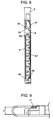
- FIG. 5 is a side view of circuit board 4 shown in FIG. 4 before folding, that is, before insertion into card case 123.
- FIG. 10 shows another preferred embodiment of the card adapter in the present invention.
- circuit board 4 is folded and inserted into card case 123, circuit board 4 is fixed by insulating adhesives applied inner face of card case 123, providing SD card connector 6 with no support for circuit board 4.
- first adhesive sheet 11 and second adhesive sheet 12 are both resin sheets having rubber adhesives such as polybuden or the like.
- the embodiment is to form the holder for a compact memory card on SD card connector 6 by first guide 65, second guide 66, third guide 67 and first metal cover 22 as shown in FIG. 3.
- the insertion direction of SD card (X) is at right angle to that of the adapter (Y) as shown in FIG. 1.
- the configuration can prevent SD card 100 inserted in card adapter 1 from being removed while running. Therefore, a mechanism to switch on/off power supply from SD card connector 6 to SD card 100 or a mechanism to detect any compact memory card in the adapter can be eliminated as shown in FIG. 4.
- main board 41 of circuit board 4 is generally L-shaped so as to prevent SD card holder 7 from being blocked when folded to the opposite face of sub-board 42 as shown in FIG. 5.
- first contact portion 44 and second contact portion 45 of circuit board 4 are appressed to first support 61 and to second support 62 respectively enabling distance (Z) between the facing circuit boards to keep a prescribed dimension.
- Still another aspect is a configuration in that signal processing circuit such as controller IC chip is not installed in circuit board 4. That is, CF slot connector 5 is connected to SD card connector 6 electrically, and that circuit to convert pin arrangement is installed in circuit board 4.
- Card adapter 1 is an assembly of first case 2 and second case 3 bonded together by ultrasonic welding to form card case 123 as shown in FIG. 1.
- First case 2 is an integral mold of first resin frame 21 and first metal cover 22.
- Second case 3 is also an integral mold of second resin frame 31 and second metal cover 32. Then, first resin frame 21 and second resin frame 31 are ultrasonically welded to complete card case 123.
- CF slot connector 5 which is a first connector compliant with the first specification, is disposed on the front edge facing CF type I slot, and SD card inlet 71 to insert SD card 100 is disposed on one side of the adapter. That is, the insertion direction (X) of SD card 100 for card adapter 1 is at right angle to the insertion direction (Y) of adapter 1.
- the configuration can provide SD card connector 6 with the minimum thickness as no press mechanism is needed to SD card 100 from above SD card connector 6.
- first case 2 and second case 3 have integral molded first metal cover 22 and second metal cover 32 respectively.
- Circuit board 4 held between first case 2 and second case 3, is appressed to first metal cover 22 and second metal cover 32.
- First insulation sheet 8 insulates main board 41 from first metal cover 22 appressed to main board 41 electrically.
- Second insulation sheet 9 insulates sub-board 42 from second metal cover 32 appressed to sub-board 42 electrically.
- SD card connector 6 surface-mounted on circuit board 4, the main part of card adapter 1, is disposed at the back of SD card holder 7.
- SD card 100 inserted from inlet 71 is coupled to card adapter 1 mechanically as well as electrically.
- SD card 100 is a sheet-type card embedding a resin packaged IC (not shown) with a plurality of terminals disposed on the bottom surface.
- Card adapter 1 has circuit board 4 internally, and circuit board 4 includes main board 41, sub-board 42 and flexible bend 43 to connect main board 41 and sub-board 42.
- Main board 41 includes mainly controller IC chip and its peripheral circuits (not shown), and is formed generally L-shaped in plan view.
- Sub-board 42 carries mainly CF slot connector 5, SD card connector 6 and its peripheral circuits (not shown).
- Flexible bend 43 includes a wiring conductor (not shown) to connect circuits between main board 41 and sub-board 42.
- Circuit board 4 includes: CF slot connector 5 compliant with the first specification; SD card connector 6 compliant with the second specification; and signal processing circuit mainly involving controller IC chip 10 and its peripheral circuits (not shown).
- a signal processing circuit (not shown) is disposed in the card adapter so as to use a compact memory card compliant with the second specification in an equipment provided with a card slot compliant with the first specification. This is because the signal processing circuit is necessary in any one of followings: equipment with a card slot; a compact memory card compliant with the second specification; and a card adapter to insert a compact memory card.
- the signal processing circuit receives, via pattern wiring of circuit board 4, signal compliant with the first specification to and from CF slot connector 5 and signal compliant with the second specification to and from SD card connector 6. Then the signal processing circuit (not shown) converts data between both specifications.
- SD card connector 6 mounted on sub-board 42 includes: terminals 63 corresponding to the terminals (not shown) disposed on the bottom surface of SD card 100; and write protect switch terminal 64 corresponding to write protect switch 101 disposed on a side surface of SD card 100.
- Terminals 63 and 64 are made of a resilient conductive material
- First support 61 and second support 62 are disposed on the top surface of external periphery of SD card connector 6.
- the configuration can hold first contact portion 44 and second contact portion 45 of main board 41 when circuit board 4 is folded, and can keep distance (Z) between main board 41 and sub-board 42 facing each other in a prescribed dimension.
- SD card connector 6 has first guide 65, second guide 66 and third guide 67 internally to limit front and right and left sides positions of inserted SD card.
- SD card 100 can be inserted to or extracted from card adapter 1 only when card adapter 1 is out of the card slot.
- the ability of insertion/removal of SD card 100 with card adapter 1 being coupled (in a running state) to equipment (not shown), so-called hot plugging, needs not be assured. Therefore, terminals to switch on/off the power supply from SD card connector 6 to SD card 100 or to detect any SD card 100 remaining in the adapter are not necessary any more.
- Both first support 61 and second support 62 disposed on the top surface of external periphery of SD card connector 6 form a step equal to the thickness of the circuit board and can provide distance (Z) between main board 41 and sub-board 42 folded to face each other in a prescribed dimension.
- circuit board 4 folded at flexible bend 43 until main board 41 faces sub-board 42, and inserted into card adapter 1 are shown in FIGs. 6 to 8.
- main board 41 is formed generally L-shaped, even if main board 41 is folded to the opposite face of sub-board 42, the top of SD card connector 6 is open. That is, main board 41 has an open area equal to or wider than SD card holder 7 at the place facing SD card holder 7.
- main board 41 is formed L-shaped to form an open area.
- the form is not limited to L-shape but for instance main board formed U-shaped for forming the open space may be also acceptable.
- the thickness of card adapter 1 can be the height stacking: first metal cover 22; SD card connector 6; sub-board 42; second insulation sheet 9; and second metal cover 32. That is, as the thickness of main board 41 is not added to the total height, card adapter 1 can be thinner accordingly.
- circuit board 4 includes main board 41, sub-board 42 and flexible bend 43 in preferred embodiment 1, integrating main board 41 and sub-board 42 can eliminate flexible bend 43.
- FIG. 10 shows the card adapter used in preferred embodiment 2 of the present invention.
- insulating adhesive is employed.
- Adhesive sheet 11 for instance, is applied on first metal cover 22 appressed to main board 41, and adhesive sheet 12 is applied on second metal cover 32 appressed to sub-board 42.
- the configuration can hold the facing distance (Z) between boards of the folded circuit board in a prescribed dimension.
- Adhesive sheet is a resinous sheet applied with rubber-based adhesives such as polybuden or the like.
- the configuration can eliminate first insulation sheet 8 and second insulation sheet 9 used in preferred embodiment 1.
- the adhesive fixing is not limited to rubber adhesives such as polybuden or the like.
- circuit board 4 having no signal processing circuit (not shown), that connects CF slot connector 5 to SD card connector 6 electrically by pattern wirings to convert pin arrangements without carrying any signal conversion can be adopted in preferred embodiment 2 of the present invention.
- Card adapter 1 having an outline identical to CF type I compliant with the CompactFlash Association Standard (the first specification) has SD card holder 7 to insert SD card 100 compliant with SD Card Association Standard (the second specification) internally. As SD card 100 is inserted in SD card holder 7 without any extrusion, card adapter 1 with inserted SD card 100 can become a CF type I card. By introducing card adapter 1 of the present invention, therefore, PDAs or digital still cameras with CF type I slot can use SD card 100.
- Card adapter 1 has the structure with: CF slot connector 5 disposed on front edge surface of card adapter 1 facing CF type I card slot; and SD card inlet 71 formed on a side surface of card adapter 1. That is, insertion direction (X) of SD card 100 with respect to card adapter 1 is at right angle to insertion direction (Y) of card adapter 1 with respect to CF type I card slot. This can prevent SD card 100 inserted in card adapter 1 from being removed while running. Consequently, there is no need to take into account the so-called "hot plugging", and detection of insertion and removal of SD card 100 in the adapter may be eliminated. Therefore, the configuration enables to design card adapter 1 easily with a simplified structure of SD card connector 6 and to improve the product reliability.
- the present invention can realize a card adapter having a signal processing circuit to convert signals between the first specification and the second specification with a card thickness compliant with CF type I, as a low profile connector for a compact memory card can be provided.
- second supports can be downsized and simplified as mechanisms to detect any compact memory card compliant with the second specification staying in the adapter can be eliminated. This can provide a cheaper second supports.
- parts consisting of the signal processing circuit can be arranged easily for the card adapter, CF type I compliant shape, having the signal processing circuit to convert signals between the first specification and second specifications.
- circuit board of the card adapter CF type I compliant shaped, having the signal processing circuit is widened, as an area of upper board of circuit boards that is folded corresponding to the compact card holder is removed. This makes it unnecessary to use a thin circuit board.
- circuit board supports This can prevent parts facing each other from being damaged by collision and can make it unnecessary to dispose other materials for electrical insulation.
- resin sheets applied with rubber adhesives such as polybuden or the like to keep the distance between the main and sub boards of the circuit board folded can prevent parts facing each other from being damaged by collision. This makes it unnecessary to dispose insulation sheets for the electrical insulation.
- the present invention can provide the card adapter with CF type I compliant thickness for a type of card adapter that performs pin arrangements between the first specification and second specifications.
Applications Claiming Priority (3)
| Application Number | Priority Date | Filing Date | Title |
|---|---|---|---|
| JP2002162499 | 2002-06-04 | ||
| JP2002162499A JP3835353B2 (ja) | 2002-06-04 | 2002-06-04 | カード接続用アダプタ |
| PCT/JP2003/006918 WO2003102863A1 (fr) | 2002-06-04 | 2003-06-02 | Adaptateur pour carte de connexion |
Publications (2)
| Publication Number | Publication Date |
|---|---|
| EP1510965A1 true EP1510965A1 (de) | 2005-03-02 |
| EP1510965A4 EP1510965A4 (de) | 2008-07-30 |
Family
ID=29706605
Family Applications (1)
| Application Number | Title | Priority Date | Filing Date |
|---|---|---|---|
| EP03730756A Withdrawn EP1510965A4 (de) | 2002-06-04 | 2003-06-02 | Kartenadapter |
Country Status (4)
| Country | Link |
|---|---|
| US (1) | US20050225950A1 (de) |
| EP (1) | EP1510965A4 (de) |
| JP (1) | JP3835353B2 (de) |
| WO (1) | WO2003102863A1 (de) |
Cited By (2)
| Publication number | Priority date | Publication date | Assignee | Title |
|---|---|---|---|---|
| EP1760627A2 (de) | 2005-08-30 | 2007-03-07 | Matsushita Electric Works, Ltd. | Speicherkartensockel |
| EP1816583A1 (de) * | 2006-02-07 | 2007-08-08 | Lumberg Connect GmbH | Kontaktiervorrichtung für eine Chipkarte |
Families Citing this family (16)
| Publication number | Priority date | Publication date | Assignee | Title |
|---|---|---|---|---|
| JP4019965B2 (ja) * | 2003-02-10 | 2007-12-12 | ソニー株式会社 | Icカードのアダプタ装置 |
| JP2004326434A (ja) * | 2003-04-24 | 2004-11-18 | Softbank Bb Corp | Pcカード及びpcカードの制御方法 |
| US8177129B2 (en) * | 2004-02-17 | 2012-05-15 | Timothy D. Larin | Interactive multimedia smart affinity card with flash memory |
| JP4384525B2 (ja) * | 2004-03-11 | 2009-12-16 | マクセル精器株式会社 | ミニカードアダプター |
| TW200818613A (en) * | 2004-11-18 | 2008-04-16 | Alps Electric Co Ltd | Connector device for card and adapter device for card |
| JP2007034612A (ja) * | 2005-07-26 | 2007-02-08 | Sony Corp | カードトレイ |
| US7381096B2 (en) * | 2005-10-28 | 2008-06-03 | Hewlett-Packard Development Company, L.P. | Media power protection system and method |
| US7310223B2 (en) * | 2005-12-09 | 2007-12-18 | Seagate Technology Llc | Electrical connector device for a disc drive |
| US7437496B2 (en) * | 2006-04-28 | 2008-10-14 | Ixia | Hot swap adapter |
| US7364468B2 (en) * | 2006-05-16 | 2008-04-29 | Stone Technology International Co., Ltd. | Dual-interface converter of miniature memory card |
| JP4821592B2 (ja) * | 2006-12-08 | 2011-11-24 | 日本電気株式会社 | 枠体の補強構造及び該構造を備えた電子機器 |
| US7713091B2 (en) * | 2008-09-12 | 2010-05-11 | Getac Technology Corp. | Adaptor device for connecting and accessing data card and computer device incorporating the adaptor device |
| CN102035069A (zh) * | 2009-09-30 | 2011-04-27 | 深圳富泰宏精密工业有限公司 | 便携式电子装置 |
| US8550858B2 (en) * | 2010-04-07 | 2013-10-08 | Apple Inc. | Extensible memory card-compatible receptacle and port expansion device |
| CN111131732B (zh) * | 2019-12-24 | 2021-10-19 | 深圳翔成电子科技有限公司 | 一种ku波段高频头 |
| JP2023143131A (ja) | 2022-03-25 | 2023-10-06 | マクセル株式会社 | 書類用スタンド |
Citations (3)
| Publication number | Priority date | Publication date | Assignee | Title |
|---|---|---|---|---|
| US5184282A (en) * | 1989-02-27 | 1993-02-02 | Mips Co., Ltd. | IC card adapter |
| US6015092A (en) * | 1998-02-05 | 2000-01-18 | Postlewaite; William M. | Smart card reader having angled smart card holder |
| US20020032813A1 (en) * | 1999-01-21 | 2002-03-14 | Taiji Hosaka | Card connection adaptor |
Family Cites Families (4)
| Publication number | Priority date | Publication date | Assignee | Title |
|---|---|---|---|---|
| US6089459A (en) * | 1992-06-16 | 2000-07-18 | Smartdiskette Gmbh | Smart diskette device adaptable to receive electronic medium |
| US5887145A (en) * | 1993-09-01 | 1999-03-23 | Sandisk Corporation | Removable mother/daughter peripheral card |
| JPH0992937A (ja) * | 1995-09-25 | 1997-04-04 | Mitsubishi Electric Corp | 印刷配線基板 |
| KR20020027732A (ko) * | 2000-10-04 | 2002-04-15 | 윤종용 | 디스크 드라이브 |
-
2002
- 2002-06-04 JP JP2002162499A patent/JP3835353B2/ja not_active Expired - Fee Related
-
2003
- 2003-06-02 EP EP03730756A patent/EP1510965A4/de not_active Withdrawn
- 2003-06-02 WO PCT/JP2003/006918 patent/WO2003102863A1/ja active Application Filing
- 2003-06-02 US US10/516,464 patent/US20050225950A1/en not_active Abandoned
Patent Citations (3)
| Publication number | Priority date | Publication date | Assignee | Title |
|---|---|---|---|---|
| US5184282A (en) * | 1989-02-27 | 1993-02-02 | Mips Co., Ltd. | IC card adapter |
| US6015092A (en) * | 1998-02-05 | 2000-01-18 | Postlewaite; William M. | Smart card reader having angled smart card holder |
| US20020032813A1 (en) * | 1999-01-21 | 2002-03-14 | Taiji Hosaka | Card connection adaptor |
Non-Patent Citations (1)
| Title |
|---|
| See also references of WO03102863A1 * |
Cited By (5)
| Publication number | Priority date | Publication date | Assignee | Title |
|---|---|---|---|---|
| EP1760627A2 (de) | 2005-08-30 | 2007-03-07 | Matsushita Electric Works, Ltd. | Speicherkartensockel |
| EP1760627A3 (de) * | 2005-08-30 | 2007-05-23 | Matsushita Electric Works, Ltd. | Speicherkartensockel |
| US7357674B2 (en) | 2005-08-30 | 2008-04-15 | Matsushita Electric Works, Ltd. | Memory card socket structure |
| CN100511847C (zh) * | 2005-08-30 | 2009-07-08 | 松下电工株式会社 | 存储卡插座结构 |
| EP1816583A1 (de) * | 2006-02-07 | 2007-08-08 | Lumberg Connect GmbH | Kontaktiervorrichtung für eine Chipkarte |
Also Published As
| Publication number | Publication date |
|---|---|
| EP1510965A4 (de) | 2008-07-30 |
| JP2004013259A (ja) | 2004-01-15 |
| JP3835353B2 (ja) | 2006-10-18 |
| US20050225950A1 (en) | 2005-10-13 |
| WO2003102863A1 (fr) | 2003-12-11 |
Similar Documents
| Publication | Publication Date | Title |
|---|---|---|
| EP1510965A1 (de) | Kartenadapter | |
| US7032827B2 (en) | Combination SD/MMC flash memory card with thirteen contact pads | |
| US7834276B2 (en) | Structure for connecting a USB communication interface in a flash memory card by the height difference of a rigid flexible board | |
| JP3530460B2 (ja) | カードコネクタ | |
| US7152801B2 (en) | Memory cards having two standard sets of contacts | |
| US7771238B2 (en) | Card-type peripheral device | |
| US6222726B1 (en) | Portable personal computer with arrangement for connecting an expansion card to a socket therein | |
| US6607405B2 (en) | Multi-card card connector for multi-type cards | |
| US7458519B2 (en) | Card tray | |
| US20050281010A1 (en) | Contact pad arrangement for integrated SD/MMC system | |
| JP3581063B2 (ja) | カードコネクタのスイッチ構造 | |
| US20040087213A1 (en) | Plug used for connection with a usb receptacle | |
| JP2001223044A (ja) | カードコネクタ | |
| US9195278B2 (en) | Foldable electrical connector-housing system and method of manufacture thereof | |
| US7325745B2 (en) | Card reader assembly | |
| US20050136744A1 (en) | Memory card connector | |
| US6642614B1 (en) | Multi-functional memory chip connector | |
| US20080189486A1 (en) | USB Flash Memory Devices with An Improved Cap | |
| CN101471502A (zh) | 电子设备 | |
| US6902435B1 (en) | Electrical connector adapted for use with different electronic cards | |
| US20110092109A1 (en) | Flash memory device and assembly thereof with improved planar contact portions | |
| JP3102935U (ja) | ユニバーサルシリアルバスのコネクター外カバーおよびメモリカード外カバーの一体成形構造 | |
| WO1997047479A1 (fr) | Equipement electronique de type carte | |
| JP3385249B2 (ja) | カードコネクタ構造 | |
| EP1515398B1 (de) | Verbinder und Verbindungseinheit |
Legal Events
| Date | Code | Title | Description |
|---|---|---|---|
| PUAI | Public reference made under article 153(3) epc to a published international application that has entered the european phase |
Free format text: ORIGINAL CODE: 0009012 |
|
| 17P | Request for examination filed |
Effective date: 20041203 |
|
| AK | Designated contracting states |
Kind code of ref document: A1 Designated state(s): AT BE BG CH CY CZ DE DK EE ES FI FR GB GR HU IE IT LI LU MC NL PT RO SE SI SK TR |
|
| AX | Request for extension of the european patent |
Extension state: AL LT LV MK |
|
| DAX | Request for extension of the european patent (deleted) | ||
| RBV | Designated contracting states (corrected) |
Designated state(s): DE FR GB |
|
| A4 | Supplementary search report drawn up and despatched |
Effective date: 20080701 |
|
| 17Q | First examination report despatched |
Effective date: 20080905 |
|
| RAP1 | Party data changed (applicant data changed or rights of an application transferred) |
Owner name: PANASONIC CORPORATION |
|
| STAA | Information on the status of an ep patent application or granted ep patent |
Free format text: STATUS: THE APPLICATION IS DEEMED TO BE WITHDRAWN |
|
| 18D | Application deemed to be withdrawn |
Effective date: 20090116 |