TECHNICAL FIELD
-
The present invention relates to a card adapter to connect a
removable compact memory card to portable information equipments
represented by PC (personal computer), PDA (personal digital assistants),
digital still camera or the like.
BACKGROUND ART
-
Recent notebook computers (personal computers) are generally
provided with PC card slots. The PC card inserted in the slot can extend
functionalities of the notebook computers.
-
The PC card satisfies the PC Card Standard with a flat rectangular
shape of 54.0 mm wide, 85.6 mm long, and 3.3 mm (type I), 5.0 mm (type II)
and 10.5 mm (type III) high respectively. However, as even the PC card is
not compact enough to meet strong requirements for downsizing in recent
portable information equipment represented by PDAs or digital still
cameras, a CF card that is more compact in size has been introduced in
many cases.
-
The CF card represented by the Flash memory card is used to store
images taken by digital still cameras or schedule and address data in PDAs.
The CF card compliant with the CompactFlash Association Standard
(hereafter referred to as the first specification) has a flat rectangular shape
of 36.4 mm wide, 42.5 mm long, and 3.3 mm (type I) and 5.0 mm (type II)
high respectively. Most recent PDAs and digital cameras adopt 3.3 mm
high model (type I) being advantageous for product downsizing.
-
On the other hand, compact memory cards specialized in memory
have been used widely for digital still cameras, silicon-audio players or the
like as a storage media. These compact memory cards having memory IC
chips or controller IC chips and directly packaged using resin have a feature
of extremely low profile. Smart media cards and MMCs (MultiMedia
Cards) belong to this category. Moreover, the SD memory card (Secure
Digital memory card) having copyright protection functions has become very
popular recently with its compact size, large capacity and high transfer rate.
Hereafter, standard for these compact memory cards is referred to
generically as the second specification.
-
The age of real multi-media has come and portable information
equipments and notebook personal computers have become very popular
due to the achievements of downsizing and high functionalities in portable
information equipment.
-
In this situation, for instance, transferring images taken by digital
still camera to notebook PCs to edit pictures on the PCs or exchanging data
between PDAs and notebook PCs are enjoyed everyday. Most notebook PCs
are, however, not provided with slots to insert the compact memory card
directly while CF cards or other compact memory cards are well established
as storage media. To meet the requirements to connect the CF cards or
compact memory cards to PC card slot formed according to the PC Card
Standard, the PC card adapter has been provided so far.
-
Most modern PDAs or digital still cameras have been provided with
slots for CF cards but have no slots to insert MMC or the SD cards directly
that have been used widely in recent years. Until now, any card adapter
compliant with 3.3 mm (type I) for PDAs or digital still cameras has not yet
been developed.
-
The reason is that designing a card adapter thinner than CF type I is
physically impossible as the compact memory cards have a thickness almost
similar to CF type I.
-
Information equipment having CF card slots compliant with the
CompactFlash Association Standard have to satisfy a precondition specified
in the standard: the compact memory card side must have a signal
processing circuit to convert signals between the first specification and the
second specification. Compact memory cards, therefore, without carrying
the signal processing circuit cannot be used directly in the CF card slots.
-
Therefore, to connect the compact memory cards to information
equipment having the CF card slots, a CF-card-shaped card adapter
provided with a signal processing circuit to convert data between both
specifications is necessary.
-
For instance, as disclosed in Japanese Patent Laid-Open Application
No. 2000-214970, conventional CF-card-shaped card adapter has slot
connectors mounted on the top surface of an internal circuit board to form a
holder for a compact memory card. On the bottom surface of the internal
circuit board, the signal processing circuit is formed to convert signals
between both specifications. Therefore, the thickness of the card adapter
can be the minimum when followings are stacked with no space in between:
a holder for a compact memory card or a slot connector; a circuit board;
parts for the signal processing circuit; and metal covers to cover top and
bottom surfaces of the card adapter.
-
Even in this case, to produce a card adapter thinner than CF type I is
physically impossible as compact memory cards have thickness near to that
specified for CF type I. Therefore, as disclosed for instance in Japanese
Patent Laid-Open Application No. 2000-214970, a card adapter compliant
with CF type II has been realized (shaped 36.4 mm wide, 42.5 mm long and
5.0 mm high as specified in CompactFlash Association Standard).
-
In another example, to allow a card adapter to connect to information
equipment having CF type I slot, a card adapter has been realized
complying the width and thickness of the card adapter with respect to the
insertion direction with CF type I and extending the longitudinal length
along the insertion direction longer than CF type I.
-
Similarly, another CF type I "compatible" card adapter has been
realized that holds a compact memory card in the holder with an end
portion extending out of the card adapter.
-
As conventional compact memory cards have thicknesses
approximately equal to the thickness specified for CF type I,
commercializing a CF type I card adapter has been physically difficult that
must satisfy following three requirements: (1) capable of connecting to
information equipment having a CF type I slot, (2) capable of including
whole of the holder for a compact memory card and the signal processing
circuit, (3) capable of holding a compact memory card without any extrusion
out of the CF type I card adapter.
-
Japanese Patent Laid-Open Application No. 2000-214970 discloses a
CompactFlash Association Standard type II compliant card adapter.
Portable information equipment, however, represented by PDA or digital
still camera has been in many cases provided with CF type I card slot due to
strong needs for downsizing. As the result, the present situation is that
many portable information equipment with CF type I card slot cannot
connect to type II card adapter.
-
Most portable information equipments are provided with a protection
lid for card slot inlet. Additionally, some of the equipments have a function
to detect closing of the lid and causing the equipment not to start operation
unless the lid is closed perfectly. Therefore, card adapters with a
longitudinal elongation along the card slot or card adapters with an inserted
compact memory card having an extrusion from the end of adapter even
though the card adapter itself has the CF type I compliant shape cannot be
used for these equipment.
-
Most usual card adapters are made up to insert a compact memory
card from the rear end. Structures of card adapter with an inserted
compact memory card having an extrusion from the end have risks to drop
off from the card adapter by unexpected external forces. In some card
adapters such as disclosed in Japanese Patent Laid-Open Application No.
2000-214970, the power supply control for compact memory cards, so-called
"hot plugging", is simplified as the aforementioned problems is solved by
modifying the adapter structure. However, detection of insertion and
removal of a compact memory card in the card adapter has been an essential
function.
SUMMARY OF THE INVENTION
-
The present invention aims at solving the conventional problems
with the first purpose of providing a CF type I card adapter that can
includes all of the holder for a compact memory card and the signal
processing circuit, and can hold a compact memory card without any
extrusion out of the CF type I card adapter.
-
The second purpose is to provide a card adapter with an improved
reliability by forming an adapter structure capable of preventing the
compact memory card from dropping off or from removing while the card
adapter is in the card slot, and a simple structure by simplifying the power
supply control for the compact memory card and by eliminating the
detection of insertion and removal of the compact memory card.
-
The card adapter of the present invention is to connect a compact
memory card compliant with the second specification to the CF card slot
compliant with the CompactFlash Association Standard or the first
specification.
-
The card adapter includes a circuit board and a card case, and
the circuit board has:
- a first connector compliant with the first specification;
- a second connector compliant with the second specification; and
- a signal processing circuit connected to the first connector and the
second connector to convert signals between the first specification and the
second specification, and
the card case accommodating and including the circuit board has:
- a compact memory card inlet perpendicular to the insertion
direction of the card slot compliant with the first specification,
wherein the card case and the second connector form the holder for
the compact memory card, and the card case makes up the top portion of the
holder for the compact memory card.-
BRIEF DESCRIPTION OF THE DRAWINGS
-
- Fig. 1 is a perspective view of an outline of the card adapter used in
the preferred embodiment of the present invention.
- Fig. 2 is a cross-sectional view of the card adapter along the line A - A
shown in FIG. 1.
- Fig. 3 is an exploded perspective view of the card adapter shown in
FIG. 1.
- Fig. 4 is a plan view of the circuit board used in the preferred
embodiment of the present invention.
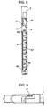
- Fig. 5 is a side view of the circuit board used in the preferred
embodiment of the present invention.
- Fig. 6 is a plan view of the circuit board in a folded condition used in
the preferred embodiment of the present invention
- Fig. 7 is a side view of the circuit board in a folded structure used in
the preferred embodiment of the present invention
- Fig. 8 is a cross-sectional view of the circuit board along the line B - B
shown in FIG. 7.
- Fig. 9 is an expanded partial side view of the circuit board in a folded
structure used in the preferred embodiment of the present invention
- Fig. 10 is an exploded perspective view of the card adapter shown in
FIG. 1.
-
DETAILED DESCRIPTION OF THE PREFERRED EMBODIMENTS
-
The card adapter of the present invention is described with reference
to drawings. As shown in FIG. 1, card adapter 1 comprises first case 2,
second case 3, CF slot connector 5, and card inlet 71. Card case 123 is an
assembly of first case 2 and second case 3. SD card 100 has a write protect
switch 101 on a side surface. An insertion direction of SD card is indicated
by arrow X, and an insertion direction of the card adapter to information
equipment is indicated by arrow Y.
-
FIG. 2 shows a cross-sectional view taken along the line A -A of card
adapter 1 shown in FIG. 1. First case 2 is an integral mold of first resin
frame 21 and first metal cover 22. Second case 3 is an integral mold of
second resin frame 31 and second metal cover 32. First resin frame 21 and
second resin frame 31 are carried out ultrasonic welding. First metal cover
22 and second metal cover 32 can shield circuit board 4 including signal
processing circuit (not shown) from external electric noises or static
electricity and can protect noise radiations from circuit board 4.
-
Circuit board 4 is sandwiched between first case 2 and second case 3.
First metal cover 22 and second metal cover 32 contact to circuit board 4.
Main board 41 is insulated electrically from first metal cover 22 appressed
to main board 41 by first insulation sheet 8 shown in FIG. 3. Similarly,
sub-board 42 is insulated electrically from second metal cover 32 appressed
to sub-board 42 by second insulation sheet 9.
-
FIG. 3 shows an exploded perspective view of card adapter 1 shown in
FIG. 1. Circuit board 4 including signal processing circuit (not shown)
comprises main board 41, sub-board 42 and flexible bend 43. Additionally,
the card adapter includes: CF slot connector 5, SD card connector 6, circuit
board first support (first support) 61, first upper support 611, circuit board
second support (second support) 62, terminals 63, first guide 65, second
guide 66, third guide 67, card inlet 71, first insulation sheet 8, second
insulation sheet 9, controller IC chip 10 and write protect switch terminal
64 as shown in FIG. 4.
-
Here, SD card connector 6 makes up a housing including first support
61, first upper support 611, second support 62, first guide 65, second guide
66 and third guide 67. SD card connector 6 includes first support 61 and
second support 62. The adapter structure allows first contact portion 44 of
circuit board 4 to touch first support 61, and second contact portion 45 of
circuit board 4 to touch second support 62 when circuit board 4 is folded to
opposite faces. If first support 61 and second support 62 have a same
height, and the step between first upper support 611 and first support 61 is
equal to the thickness of circuit board 4, the bottom surface of circuit board
4 and first upper support 611 come to a same level when circuit board 4 is
folded.
-
FIG. 4 is a plan view showing whole of the circuit board shown in FIG.
3. The card adapter has a structure so as to form SD card holder 7 by first
guide 65, second guide 66 and third guide 67 of SD card connector 6
respectively. FIG. 5 is a side view of circuit board 4 shown in FIG. 4 before
folding, that is, before insertion into card case 123.
-
FIG. 10 shows another preferred embodiment of the card adapter in
the present invention. After circuit board 4 is folded and inserted into card
case 123, circuit board 4 is fixed by insulating adhesives applied inner face
of card case 123, providing SD card connector 6 with no support for circuit
board 4. For instance, first adhesive sheet 11 and second adhesive sheet 12
are both resin sheets having rubber adhesives such as polybuden or the like.
The embodiment is to form the holder for a compact memory card on SD
card connector 6 by first guide 65, second guide 66, third guide 67 and first
metal cover 22 as shown in FIG. 3.
-
In another aspect of the present invention, the insertion direction of
SD card (X) is at right angle to that of the adapter (Y) as shown in FIG. 1.
The configuration can prevent SD card 100 inserted in card adapter 1 from
being removed while running. Therefore, a mechanism to switch on/off
power supply from SD card connector 6 to SD card 100 or a mechanism to
detect any compact memory card in the adapter can be eliminated as shown
in FIG. 4.
-
Still another aspect is that main board 41 of circuit board 4 is
generally L-shaped so as to prevent SD card holder 7 from being blocked
when folded to the opposite face of sub-board 42 as shown in FIG. 5.
-
Still another aspect is described with reference to FIGs. 5 & 6.
When main board 41 is folded to the opposite face of sub-board 42, first
contact portion 44 and second contact portion 45 of circuit board 4 are
appressed to first support 61 and to second support 62 respectively enabling
distance (Z) between the facing circuit boards to keep a prescribed
dimension.
-
Still another aspect is described again with reference to FIGs. 5 & 6.
When main board 41 is folded to the opposite face of sub-board 42, first
adhesive sheet 11 and second adhesive sheet 12 provided on first metal
cover 22 and on second metal cover 32 respectively, resinous sheets applied
with rubber-based adhesives such as polybuden or the like as shown in FIG.
10 can keep distance (Z) between the facing circuit boards in a prescribed
dimension.
-
Still another aspect is a configuration in that signal processing circuit
such as controller IC chip is not installed in circuit board 4. That is, CF
slot connector 5 is connected to SD card connector 6 electrically, and that
circuit to convert pin arrangement is installed in circuit board 4.
(PREFERRED EMBODIMENT 1)
-
The card adapter of the present invention is described in detail
further with reference to preferred embodiment 1.
-
Card adapter 1 is an assembly of first case 2 and second case 3
bonded together by ultrasonic welding to form card case 123 as shown in
FIG. 1. First case 2 is an integral mold of first resin frame 21 and first
metal cover 22. Second case 3 is also an integral mold of second resin
frame 31 and second metal cover 32. Then, first resin frame 21 and second
resin frame 31 are ultrasonically welded to complete card case 123.
-
Circuit board 4 including signal processing circuit (not shown) as a
main part, is folded and held in card case 123 composed of first case 2 and
second case 3 bonded together.
-
CF slot connector 5, which is a first connector compliant with the first
specification, is disposed on the front edge facing CF type I slot, and SD card
inlet 71 to insert SD card 100 is disposed on one side of the adapter. That
is, the insertion direction (X) of SD card 100 for card adapter 1 is at right
angle to the insertion direction (Y) of adapter 1.
-
In this embodiment, the top of SD card connector 6, which is a second
connector compliant with the second specification, contacts first metal cover
22. Therefore, SD card connector 6 and first metal cover 22 hold SD card
100 inserted in SD card holder 7. The configuration can provide SD card
connector 6 with the minimum thickness as no press mechanism is needed
to SD card 100 from above SD card connector 6.
-
To shield circuit board 4 from external electric noise or static
electricity and to protect noise radiations from circuit board 4, first case 2
and second case 3 have integral molded first metal cover 22 and second
metal cover 32 respectively.
-
Circuit board 4, held between first case 2 and second case 3, is
appressed to first metal cover 22 and second metal cover 32. First
insulation sheet 8 insulates main board 41 from first metal cover 22
appressed to main board 41 electrically. Second insulation sheet 9
insulates sub-board 42 from second metal cover 32 appressed to sub-board
42 electrically.
-
SD card connector 6 surface-mounted on circuit board 4, the main
part of card adapter 1, is disposed at the back of SD card holder 7. SD card
100 inserted from inlet 71 is coupled to card adapter 1 mechanically as well
as electrically.
-
SD card 100 is a sheet-type card embedding a resin packaged IC (not
shown) with a plurality of terminals disposed on the bottom surface.
-
Card adapter 1 has circuit board 4 internally, and circuit board 4
includes main board 41, sub-board 42 and flexible bend 43 to connect main
board 41 and sub-board 42.
-
Main board 41 includes mainly controller IC chip and its peripheral
circuits (not shown), and is formed generally L-shaped in plan view.
-
Sub-board 42 carries mainly CF slot connector 5, SD card connector 6
and its peripheral circuits (not shown).
-
Flexible bend 43 includes a wiring conductor (not shown) to connect
circuits between main board 41 and sub-board 42.
-
Circuit board 4 includes: CF slot connector 5 compliant with the first
specification; SD card connector 6 compliant with the second specification;
and signal processing circuit mainly involving controller IC chip 10 and its
peripheral circuits (not shown).
-
A signal processing circuit (not shown) is disposed in the card adapter
so as to use a compact memory card compliant with the second specification
in an equipment provided with a card slot compliant with the first
specification. This is because the signal processing circuit is necessary in
any one of followings: equipment with a card slot; a compact memory card
compliant with the second specification; and a card adapter to insert a
compact memory card.
-
The signal processing circuit (not shown) receives, via pattern wiring
of circuit board 4, signal compliant with the first specification to and from
CF slot connector 5 and signal compliant with the second specification to
and from SD card connector 6. Then the signal processing circuit (not
shown) converts data between both specifications.
-
SD card connector 6 mounted on sub-board 42 includes: terminals 63
corresponding to the terminals (not shown) disposed on the bottom surface
of SD card 100; and write protect switch terminal 64 corresponding to write
protect switch 101 disposed on a side surface of SD card 100. Terminals 63
and 64 are made of a resilient conductive material
-
First support 61 and second support 62 are disposed on the top
surface of external periphery of SD card connector 6. The configuration can
hold first contact portion 44 and second contact portion 45 of main board 41
when circuit board 4 is folded, and can keep distance (Z) between main
board 41 and sub-board 42 facing each other in a prescribed dimension.
-
SD card connector 6 has first guide 65, second guide 66 and third
guide 67 internally to limit front and right and left sides positions of
inserted SD card.
-
As the insertion direction (X) of SD card is at right angle to the
insertion direction (Y) of the card adapter, SD card 100 can be inserted to or
extracted from card adapter 1 only when card adapter 1 is out of the card
slot. As a result, the ability of insertion/removal of SD card 100 with card
adapter 1 being coupled (in a running state) to equipment (not shown),
so-called hot plugging, needs not be assured. Therefore, terminals to
switch on/off the power supply from SD card connector 6 to SD card 100 or
to detect any SD card 100 remaining in the adapter are not necessary any
more.
-
Both first support 61 and second support 62 disposed on the top
surface of external periphery of SD card connector 6 form a step equal to the
thickness of the circuit board and can provide distance (Z) between main
board 41 and sub-board 42 folded to face each other in a prescribed
dimension.
-
At the time, what is important is that parts mounted on main board
41 and facing parts mounted on sub-board 42 must be disposed so as not to
collide with each other. That is, a 3 dimensional designing is required to
dispose parts such that the sum of heights of facing parts does not exceed
the distance (Z) between two facing boards when circuit board 4 is folded.
-
Structure of circuit board 4, folded at flexible bend 43 until main
board 41 faces sub-board 42, and inserted into card adapter 1 are shown in
FIGs. 6 to 8. As main board 41 is formed generally L-shaped, even if main
board 41 is folded to the opposite face of sub-board 42, the top of SD card
connector 6 is open. That is, main board 41 has an open area equal to or
wider than SD card holder 7 at the place facing SD card holder 7. In
preferred embodiment 1, main board 41 is formed L-shaped to form an open
area. However, the form is not limited to L-shape but for instance main
board formed U-shaped for forming the open space may be also acceptable.
As main board 41 does not cover SD card connector 6, the thickness of card
adapter 1 can be the height stacking: first metal cover 22; SD card connector
6; sub-board 42; second insulation sheet 9; and second metal cover 32.
That is, as the thickness of main board 41 is not added to the total height,
card adapter 1 can be thinner accordingly.
-
Though circuit board 4 includes main board 41, sub-board 42 and
flexible bend 43 in preferred embodiment 1, integrating main board 41 and
sub-board 42 can eliminate flexible bend 43.
(PREFERRED EMBODIMENT 2)
-
Next, preferred embodiment 2 that provides distance between main
board 41 and sub-board 42 of folded circuit board 4 with a prescribed
dimension is described
-
FIG. 10 shows the card adapter used in preferred embodiment 2 of
the present invention. Instead of first support 61 and second support 62
used for SD card connector 6 in preferred embodiment 1, insulating
adhesive is employed. Adhesive sheet 11, for instance, is applied on first
metal cover 22 appressed to main board 41, and adhesive sheet 12 is applied
on second metal cover 32 appressed to sub-board 42. The configuration can
hold the facing distance (Z) between boards of the folded circuit board in a
prescribed dimension. Adhesive sheet is a resinous sheet applied with
rubber-based adhesives such as polybuden or the like. The configuration
can eliminate first insulation sheet 8 and second insulation sheet 9 used in
preferred embodiment 1.
-
Needless to say, the adhesive fixing is not limited to rubber adhesives
such as polybuden or the like.
-
Additionally, needless to say, even a kind of circuit board 4, having no
signal processing circuit (not shown), that connects CF slot connector 5 to
SD card connector 6 electrically by pattern wirings to convert pin
arrangements without carrying any signal conversion can be adopted in
preferred embodiment 2 of the present invention.
-
Next, the operation of card adapter of the present invention is
described.
-
Card adapter 1 having an outline identical to CF type I compliant
with the CompactFlash Association Standard (the first specification) has SD
card holder 7 to insert SD card 100 compliant with SD Card Association
Standard (the second specification) internally. As SD card 100 is inserted
in SD card holder 7 without any extrusion, card adapter 1 with inserted SD
card 100 can become a CF type I card. By introducing card adapter 1 of the
present invention, therefore, PDAs or digital still cameras with CF type I
slot can use SD card 100.
-
Card adapter 1 has the structure with: CF slot connector 5 disposed
on front edge surface of card adapter 1 facing CF type I card slot; and SD
card inlet 71 formed on a side surface of card adapter 1. That is, insertion
direction (X) of SD card 100 with respect to card adapter 1 is at right angle
to insertion direction (Y) of card adapter 1 with respect to CF type I card
slot. This can prevent SD card 100 inserted in card adapter 1 from being
removed while running. Consequently, there is no need to take into
account the so-called "hot plugging", and detection of insertion and removal
of SD card 100 in the adapter may be eliminated. Therefore, the
configuration enables to design card adapter 1 easily with a simplified
structure of SD card connector 6 and to improve the product reliability.
-
Although the embodiments are explained when the invention is
applied to SD card, the invention is also applied to Multi Media Card.
INDUSTRIAL APPLICABILITY
-
As described above, the present invention can realize a card adapter
having a signal processing circuit to convert signals between the first
specification and the second specification with a card thickness compliant
with CF type I, as a low profile connector for a compact memory card can be
provided.
-
Additionally, the structure of second supports can be downsized and
simplified as mechanisms to detect any compact memory card compliant
with the second specification staying in the adapter can be eliminated.
This can provide a cheaper second supports. At the same time, parts
consisting of the signal processing circuit can be arranged easily for the card
adapter, CF type I compliant shape, having the signal processing circuit to
convert signals between the first specification and second specifications.
-
Additionally, the thickness limit of circuit board of the card adapter,
CF type I compliant shaped, having the signal processing circuit is widened,
as an area of upper board of circuit boards that is folded corresponding to
the compact card holder is removed. This makes it unnecessary to use a
thin circuit board.
-
Additionally, the distance between the main board and sub board of
the circuit board folded to opposite faces and inserted into a card case is
kept by circuit board supports. This can prevent parts facing each other
from being damaged by collision and can make it unnecessary to dispose
other materials for electrical insulation.
-
Additionally, resin sheets applied with rubber adhesives such as
polybuden or the like to keep the distance between the main and sub boards
of the circuit board folded can prevent parts facing each other from being
damaged by collision. This makes it unnecessary to dispose insulation
sheets for the electrical insulation.
-
Additionally, the present invention can provide the card adapter with
CF type I compliant thickness for a type of card adapter that performs pin
arrangements between the first specification and second specifications.