EP1510752A1 - Brennstoffbehälter mit Thermosicherung - Google Patents
Brennstoffbehälter mit Thermosicherung Download PDFInfo
- Publication number
- EP1510752A1 EP1510752A1 EP03019184A EP03019184A EP1510752A1 EP 1510752 A1 EP1510752 A1 EP 1510752A1 EP 03019184 A EP03019184 A EP 03019184A EP 03019184 A EP03019184 A EP 03019184A EP 1510752 A1 EP1510752 A1 EP 1510752A1
- Authority
- EP
- European Patent Office
- Prior art keywords
- cartridge
- fuel
- thermal fuse
- limit temperature
- fuel cartridge
- Prior art date
- Legal status (The legal status is an assumption and is not a legal conclusion. Google has not performed a legal analysis and makes no representation as to the accuracy of the status listed.)
- Granted
Links
- 239000000446 fuel Substances 0.000 title claims description 57
- 238000013021 overheating Methods 0.000 title 1
- 239000012530 fluid Substances 0.000 claims description 17
- 238000000605 extraction Methods 0.000 claims description 7
- 230000007246 mechanism Effects 0.000 claims description 5
- 239000000155 melt Substances 0.000 claims description 5
- 230000002441 reversible effect Effects 0.000 claims description 5
- 230000000740 bleeding effect Effects 0.000 abstract 1
- OKKJLVBELUTLKV-UHFFFAOYSA-N Methanol Chemical compound OC OKKJLVBELUTLKV-UHFFFAOYSA-N 0.000 description 12
- 239000001993 wax Substances 0.000 description 12
- 238000002844 melting Methods 0.000 description 7
- 230000008018 melting Effects 0.000 description 7
- 230000006835 compression Effects 0.000 description 6
- 238000007906 compression Methods 0.000 description 6
- 230000002093 peripheral effect Effects 0.000 description 3
- 230000009471 action Effects 0.000 description 2
- 230000002427 irreversible effect Effects 0.000 description 2
- 239000012188 paraffin wax Substances 0.000 description 2
- 238000007789 sealing Methods 0.000 description 2
- 239000000126 substance Substances 0.000 description 2
- 230000001960 triggered effect Effects 0.000 description 2
- 230000001154 acute effect Effects 0.000 description 1
- 230000004888 barrier function Effects 0.000 description 1
- 230000015572 biosynthetic process Effects 0.000 description 1
- 238000004891 communication Methods 0.000 description 1
- 230000006378 damage Effects 0.000 description 1
- 230000000694 effects Effects 0.000 description 1
- 230000000763 evoking effect Effects 0.000 description 1
- 238000004880 explosion Methods 0.000 description 1
- 239000002360 explosive Substances 0.000 description 1
- 239000007789 gas Substances 0.000 description 1
- 230000004941 influx Effects 0.000 description 1
- 239000007788 liquid Substances 0.000 description 1
- 238000004519 manufacturing process Methods 0.000 description 1
- 239000000463 material Substances 0.000 description 1
- 238000000034 method Methods 0.000 description 1
- 238000003825 pressing Methods 0.000 description 1
- 230000008569 process Effects 0.000 description 1
- 238000005070 sampling Methods 0.000 description 1
- 239000007787 solid Substances 0.000 description 1
- 230000007704 transition Effects 0.000 description 1
Images
Classifications
-
- H—ELECTRICITY
- H01—ELECTRIC ELEMENTS
- H01M—PROCESSES OR MEANS, e.g. BATTERIES, FOR THE DIRECT CONVERSION OF CHEMICAL ENERGY INTO ELECTRICAL ENERGY
- H01M8/00—Fuel cells; Manufacture thereof
- H01M8/04—Auxiliary arrangements, e.g. for control of pressure or for circulation of fluids
- H01M8/04082—Arrangements for control of reactant parameters, e.g. pressure or concentration
- H01M8/04201—Reactant storage and supply, e.g. means for feeding, pipes
- H01M8/04208—Cartridges, cryogenic media or cryogenic reservoirs
-
- F—MECHANICAL ENGINEERING; LIGHTING; HEATING; WEAPONS; BLASTING
- F16—ENGINEERING ELEMENTS AND UNITS; GENERAL MEASURES FOR PRODUCING AND MAINTAINING EFFECTIVE FUNCTIONING OF MACHINES OR INSTALLATIONS; THERMAL INSULATION IN GENERAL
- F16K—VALVES; TAPS; COCKS; ACTUATING-FLOATS; DEVICES FOR VENTING OR AERATING
- F16K17/00—Safety valves; Equalising valves, e.g. pressure relief valves
- F16K17/36—Safety valves; Equalising valves, e.g. pressure relief valves actuated in consequence of extraneous circumstances, e.g. shock, change of position
- F16K17/38—Safety valves; Equalising valves, e.g. pressure relief valves actuated in consequence of extraneous circumstances, e.g. shock, change of position of excessive temperature
- F16K17/383—Safety valves; Equalising valves, e.g. pressure relief valves actuated in consequence of extraneous circumstances, e.g. shock, change of position of excessive temperature the valve comprising fusible, softening or meltable elements, e.g. used as link, blocking element, seal, closure plug
-
- F—MECHANICAL ENGINEERING; LIGHTING; HEATING; WEAPONS; BLASTING
- F17—STORING OR DISTRIBUTING GASES OR LIQUIDS
- F17C—VESSELS FOR CONTAINING OR STORING COMPRESSED, LIQUEFIED OR SOLIDIFIED GASES; FIXED-CAPACITY GAS-HOLDERS; FILLING VESSELS WITH, OR DISCHARGING FROM VESSELS, COMPRESSED, LIQUEFIED, OR SOLIDIFIED GASES
- F17C13/00—Details of vessels or of the filling or discharging of vessels
- F17C13/06—Closures, e.g. cap, breakable member
-
- F—MECHANICAL ENGINEERING; LIGHTING; HEATING; WEAPONS; BLASTING
- F17—STORING OR DISTRIBUTING GASES OR LIQUIDS
- F17C—VESSELS FOR CONTAINING OR STORING COMPRESSED, LIQUEFIED OR SOLIDIFIED GASES; FIXED-CAPACITY GAS-HOLDERS; FILLING VESSELS WITH, OR DISCHARGING FROM VESSELS, COMPRESSED, LIQUEFIED, OR SOLIDIFIED GASES
- F17C2205/00—Vessel construction, in particular mounting arrangements, attachments or identifications means
- F17C2205/03—Fluid connections, filters, valves, closure means or other attachments
- F17C2205/0302—Fittings, valves, filters, or components in connection with the gas storage device
- F17C2205/0311—Closure means
-
- F—MECHANICAL ENGINEERING; LIGHTING; HEATING; WEAPONS; BLASTING
- F17—STORING OR DISTRIBUTING GASES OR LIQUIDS
- F17C—VESSELS FOR CONTAINING OR STORING COMPRESSED, LIQUEFIED OR SOLIDIFIED GASES; FIXED-CAPACITY GAS-HOLDERS; FILLING VESSELS WITH, OR DISCHARGING FROM VESSELS, COMPRESSED, LIQUEFIED, OR SOLIDIFIED GASES
- F17C2250/00—Accessories; Control means; Indicating, measuring or monitoring of parameters
- F17C2250/06—Controlling or regulating of parameters as output values
- F17C2250/0605—Parameters
- F17C2250/0631—Temperature
-
- Y—GENERAL TAGGING OF NEW TECHNOLOGICAL DEVELOPMENTS; GENERAL TAGGING OF CROSS-SECTIONAL TECHNOLOGIES SPANNING OVER SEVERAL SECTIONS OF THE IPC; TECHNICAL SUBJECTS COVERED BY FORMER USPC CROSS-REFERENCE ART COLLECTIONS [XRACs] AND DIGESTS
- Y02—TECHNOLOGIES OR APPLICATIONS FOR MITIGATION OR ADAPTATION AGAINST CLIMATE CHANGE
- Y02E—REDUCTION OF GREENHOUSE GAS [GHG] EMISSIONS, RELATED TO ENERGY GENERATION, TRANSMISSION OR DISTRIBUTION
- Y02E60/00—Enabling technologies; Technologies with a potential or indirect contribution to GHG emissions mitigation
- Y02E60/30—Hydrogen technology
- Y02E60/50—Fuel cells
Definitions
- the invention relates to a thermal fuse for a fluid container, in particular a fuel cartridge with such a thermal fuse, which is above a certain Limit temperature does not allow opening the cartridge.
- Fuel cartridges containing liquids or gases used to supply a consumer are used are usually closed fluid-tight for safety reasons, if fuel is not being extracted from them. As a result, can at elevated ambient temperatures, which occur in unfavorable cases can, e.g. in a car parked in the blazing sun (where on the dashboard Temperatures reaching 80 ° C and above) or on a dark Surface in direct sunlight, build up a high pressure in a cartridge. Will now such a high pressure fuel cartridge to a Consumer, e.g. a fuel cell system, connected, so may the sudden, possibly explosive, escaping of a large Fuel quantity from the cartridge facilities of the system, in particular also the fuel cells themselves are destroyed (e.g., by uncontrolled influx of too much methanol). There is also the danger that fuel escapes to the outside and the environment contaminated or evoked an acute fire / explosion hazard.
- This fuel cartridge comprises a closure device, a connection device, with an appropriately trained counterpart of a fluid removal device is connectable, wherein an opening of the closure device a fluid removal allowed over the counterpart, and a thermal fuse, after passing a limit temperature causes the opening of the closure device not possible.
- connection device is preferably designed so that only the counterpart to the connection device, which is part of a fluid extraction device, which is connected to the fuel cartridge for the purpose of fuel extraction, is suitable for fluid removal.
- the connection device can be designed in such a way that the cartridge is opened by the connection process via the counterpart.
- the opening can also be achieved by a separate operation for actuating the closure device respectively.
- the connection device can be so be configured that the opening of a separate operation for actuating the closure device but this is only possible if the connection device connected to the counterpart.
- the opening of the cartridge and the fluid removal from the fuel cartridge according to the invention are no longer possible even with the right counterpart, after a certain limit temperature has been exceeded. This can be the opening the cartridge, i. the actuation of the closure device to different Way be prevented.
- the thermal fuse can in case (2) include, for example, a lock that at Exceeding the limit temperature is triggered in the connection device and the connection of connection device and counterpart prevents.
- the thermal fuse is so designed such that after exceeding a limit temperature, a fuel extraction from the cartridge is not possible, regardless of whether the fuel cartridge before / at the exceeding of the limit temperature connected to the counterpart was.
- This training provides increased security in the handling of Fuel cartridge.
- the thermal fuse is part of the closure device.
- the Thermal fuse for example, include a valve, with another, mechanically operable valve of the closure device in the outlet channel of the cartridge connected in series. The normal condition of the thermal fuse valve is "open"; when the limit temperature is exceeded, this valve closes so that the cartridge regardless of the position of the other, mechanically actuated Valve is closed.
- the thermal fuse of the fuel cartridge comprises a reversible Mechanism, the opening of the cartridge and thus the fuel extraction again possible as soon as the temperature falls below the limit temperature again.
- a reversible mechanism can be formed for example by bimetallic elements become.
- the thermal fuse is against formed irreversible, so that after a single exceeding of a limit temperature opening of the cartridge is no longer possible, i. even if the Temperature has fallen below the limit temperature again.
- the irreversibly formed thermal fuse comprises a component from a melting substance that exceeds the limit temperature melts.
- Such a substance may be a wax type (eg paraffin).
- paraffins C n H 2n + 2
- n for example from about 30 ° C to about 90 ° C for n between 18 and 48, ie approximately a gradation of the melting temperatures of 2 ° C.
- a thermal fuse with a lying in this range limit temperature can thus be realized with a suitable paraffin with an accuracy of about one degree.
- thermal fuse does not require complex mechanics, as may be the case for realizing a reversible mechanism is.
- the fusible component may define an abutment, the Melting abolishes the function as an abutment and triggers a mechanism which no longer permits that when connecting counterpart and connection device a fluid connection is made, or alternatively prevents the counterpart can ever be connected to the connection device.
- the essential Advantages of a thermal fuse are the high temperature accuracy and the same low cost.
- the fuel cartridge comprises a display device, indicating when it is not possible to open the cartridge. This can Among other things, be avoided that the connection device or the associated Counterpart of a sampling device while trying to use the fuel cartridge to be opened, damaged.
- the display device is preferably by the Triggering the thermal fuse activated.
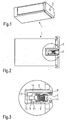
- Fig. 1 is a schematic three-dimensional view of a fuel cartridge 1, the can be used in the removal device of a fuel cell system, with this fuel, such as methanol in a DMFC (Direct methanol Fuel Cell) fuel cell.
- the fuel cartridge 1 has a connection device 2, in which a suitably trained removal device to introduce is to remove fuel from the cartridge.
- Closure device 3 comprises elements which close the cartridge in a fluid-tight manner, if there is no fuel extraction, and elements that allow it, that the cartridge 1 by connecting with the appropriately trained Counterpart 20 of the removal device can be opened.
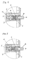
- closure device 3 For a better explanation of the closure device 3 is in Fig. 2 with a Circle surrounded section in the region of the closure device 3 in Fig. 3 in a reproduced enlarged representation.
- the closure device 3 is in a first bore 11 provided that ends on the consumer side with the connection device 2.
- the cartridge-side end of the first bore 11 is followed by a coaxial second bore 12 with a smaller cross section, which at its cartridge side End communicates with a perpendicular thereto provided third bore 13.
- Latter in turn communicates with a fourth bore 14 which is parallel to the first 11 and second bore 12 extends.
- first and second bores 11, 12 are, starting in the order of the outlet side, the following components of the closure device 3 are provided: an exhaust valve 4, a compression spring 6, a safety valve 5, and a solid Wax plug 7.
- the compression spring 6 is provided between outlet valve 4 and safety valve 5, that they pressurize these two, axially movable movable valves each other.
- the two valves 4 and 5 each comprise a more or less axisymmetric Valve body, each having a first portion with a lesser (not necessarily constant) diameter and a second section with a larger diameter, which is slightly smaller than the diameter of the first bore 11, so that a clean and play free axial guidance of Valves in the first hole is guaranteed.
- the second section with the larger one Diameter in the illustrated preferred embodiment also in each case an axial bore which serves to receive the compression spring 6.
- the two valve bodies are provided so that the two sections with larger Diameter opposite and the two axial holes each one Record end of compression spring 6.
- valve bodies are not sealing Have function. Rather, between the valve bodies and the inner wall of the first bore 11, the fuel fluid can flow in the axial direction. To one To allow or improve such flow, therefore, in the peripheral area the valve body grooves may be provided (not shown).
- the sealing function is filled with O-rings that slip over the smaller diameter section are and abut the front surface, which at the transition from the section with lesser Diameter is formed to the section of larger diameter.
- the insert body 8 has on its inside a radially extending groove in the another O-ring is fitted. This O-ring ensures that the counterpart 20 a removal device in the connection device 2 under training a fluid-tight connection can be introduced.
- the wax plug 7 which fills a cartridge-side portion of the second bore 12, serves as a cartridge-side stop (Wideriager) for the opened safety valve 5 (As a cartridge-side stop for the closed safety valve 5 serves the annular end face of the first bore 11 through the second bore 12 is pierced; see. also Fig. 5).
- the third and fourth holes form an escape channel 13, 14, in which the molten Wax after exceeding the melting temperature under action displaced axially displaced in the direction of the cartridge interior safety valve 5 becomes.
- the Wachsart and thus the melting temperature is according to the desired Limit temperature selected.
- the escape channel 13, 14 must be sufficient be large enough to absorb all the melted wax to be able to.
- the fourth bore 14 extends even to the outside of the cartridge and is there open or with a viewing window locked. This allows to visually check whether the original fixed Wax plug 7 is still intact, or whether the limit temperature is exceeded or has been exceeded in the meantime and thus wax in the escape channel 13, 14th was displaced.
- Fig. 4 now shows how using one of the connector 2 of the cartridge 1 matching counterpart 20 a removal device fuel from the cartridge 1 can be taken.
- the outlet valve 4 becomes axially in the direction of the cartridge interior shifted so that the O-ring of the exhaust valve the interior the first bore 11 no longer against its outer region (in the region of the connection device 2) seals, i. the exhaust valve 4 is opened.
- the counterpart 20 lies in its cylindrical peripheral region sealingly on the O-ring of the Insert body 8, so that fuel exclusively via a cannula 21 in the counterpart 20 can be dissipated.
- the pressing pressure of this O-ring on the peripheral portion of the counterpart 20 can be sufficient to establish a stable mechanical connection between cartridge 1 and To ensure counterpart 20. But it can also not shown facilities provided for a mechanical locking of the counterpart 20 to the cartridge 1 become.
- FIG. 5 which is executed analogously to FIG. 4, now shows the situation which exists when the specified limit temperature is exceeded (or was).
- wax plug 7 is melted and the molten wax 7 'was passed through the in the second bore 12 End of the body of the safety valve 5 under expansion of the compression spring 6 in the Dodge channel 13, 14 displaced.
- the fluid communication between the channel 9 and the first bore 11 is interrupted: the safety valve 5 - and thus the entire closure device 3 - is closed and a fluid removal from the fuel reservoir in the cartridge 1 is no longer possible (any residual amount in the region of the first bore 11th can be neglected).
- the dimension of the escape passage 13, 14 and the amount of wax 7 are preferably chosen so that the melting or molten wax 7 'in a Viewing window at the end of the fourth bore 14 causes a colored mark, the the user the non-usability of the cartridge 1 signals. This can also be a "Educational effect" to be exercised for the user.
- the fuel cartridge to be filled with methanol 1 designed so that the external structure of a certain internal pressure (preferably 1-2 bar overpressure) withstands.
- the invention also includes reversible formed thermal fuses, e.g. Use bimetallic strips, which are themselves behave almost reversibly with respect to temperature changes.
- Alternative embodiments consist of a thermally activated, mechanical barrier in the connection area, which prevents the mechanical connection of the fuel cartridge.
- Replaceable fuel cartridges are subject to enormous cost pressure.
- the present invention which is structurally easy to implement and The use of extremely low-cost materials becomes more effective "Protection at high temperatures" allows, without affecting the manufacturing costs increase significantly for a fuel cartridge.
Landscapes
- Engineering & Computer Science (AREA)
- General Engineering & Computer Science (AREA)
- Mechanical Engineering (AREA)
- Sustainable Development (AREA)
- Sustainable Energy (AREA)
- Chemical & Material Sciences (AREA)
- Chemical Kinetics & Catalysis (AREA)
- Electrochemistry (AREA)
- General Chemical & Material Sciences (AREA)
- Life Sciences & Earth Sciences (AREA)
- Manufacturing & Machinery (AREA)
- Safety Valves (AREA)
- Cooling, Air Intake And Gas Exhaust, And Fuel Tank Arrangements In Propulsion Units (AREA)
- Fuel Cell (AREA)
- Fuses (AREA)
Abstract
Description
- Fig. 1:
- eine schematische 3D-Ansicht einer Brennstoffpatrone;
- Fig. 2:
- eine Schnittansicht der in Fig. 1 gezeigten Brennstoffpatrone;
- Fig. 3:
- einen vergrößerten Ausschnitt der in Fig. 2 gezeigten Brennstoffpatrone im Bereich der Anschlusseinrichtung;
- Fig. 4:
- den Ausschnitt von Fig. 3 nach dem Öffnen durch Verbinden mit einem Gegenstück einer Entnahmevorrichtung;
- Fig. 5:
- den Ausschnitt von Fig. 3 und Fig. 4 nach dem Schließen des Sicherheitsventils nach dem Überschreiten einer vorgegebenen Grenztemperatur.
Claims (10)
- Brennstoffpatrone (1), umfassend:eine Verschlusseinrichtung (3),eine Anschlusseinrichtung (2), die mit einem entsprechend ausgebildeten Gegenstück (20) einer Fluidentnahmevorrichtung verbindbar ist, wobei ein Öffnen der Verschlusseinrichtung (3) eine Fluidentnahme über das Gegenstück (20) erlaubt,eine Thermosicherung (5,6,7), die nach Überschreiten einer Grenztemperatur bewirkt, dass das Öffnen der Verschlusseinrichtung (3) nicht möglich ist.
- Brennstoffpatrone (1) nach Anspruch 1, wobei die Thermosicherung (5,6,7) so ausgebildet ist, dass bei überschrittener Grenztemperatur eine Brennstoffentnahme aus der Patrone (1) nicht möglich ist.
- Brennstoffpatrone (1) nach Anspruch 1 oder 2, wobei die Verschlusseinrichtung (3) die Thermosicherung (5,6,7) umfasst.
- Brennstoffpatrone (1) nach einem der Ansprüche 1 bis 3, wobei die Thermosicherung einen reversiblen Mechanismus umfasst.
- Brennstoffpatrone (1) nach einem der Ansprüche 1 bis 3, wobei die Thermosicherung (5,6,7) irreversibel ausgebildet ist, so dass nach einem einmaligen Überschreiten einer Grenztemperatur kein Öffnen der Patrone (1) mehr möglich ist.
- Brennstoffpatrone (1) nach Anspruch 5, wobei die Thermosicherung (5,6,7) wenigstens eine Komponente (7) umfasst, die beim Überschreiten der Grenztemperatur schmilzt.
- Brennstoffpatrone (1) nach Anspruch 6, wobei die wenigstens eine Komponente (7) eine Wachsart umfasst, die beim Überschreiten der Grenztemperatur schmilzt.
- Brennstoffpatrone (1) nach Anspruch 6 oder 7, wobei die wenigstens eine Komponente (7) ein Widerlager für ein Sicherheitsventil (5) darstellt, wobei die Funktion als Widerlager aufgehoben wird, wenn die wenigstens eine Komponente (7) schmilzt oder geschmolzen ist.
- Brennstoffpatrone (1) nach einem der vorangegangenen Ansprüche, umfassend:eine Anzeigeeinrichtung, die anzeigt, wenn das Öffnen der Verschlusseinrichtung (4,6) nicht möglich ist.
- Brennstoffpatrone (1) nach Anspruch 9, wobei die Anzeigeeinrichtung durch die Thermosicherung aktiviert wird.
Priority Applications (4)
| Application Number | Priority Date | Filing Date | Title |
|---|---|---|---|
| EP03019184A EP1510752B1 (de) | 2003-08-25 | 2003-08-25 | Brennstoffbehälter mit Thermosicherung |
| DE50305501T DE50305501D1 (de) | 2003-08-25 | 2003-08-25 | Brennstoffbehälter mit Thermosicherung |
| AT03019184T ATE343761T1 (de) | 2003-08-25 | 2003-08-25 | Brennstoffbehälter mit thermosicherung |
| PCT/EP2004/008993 WO2005022029A1 (de) | 2003-08-25 | 2004-08-11 | Brennstoffbehälter mit thermosicherung |
Applications Claiming Priority (1)
| Application Number | Priority Date | Filing Date | Title |
|---|---|---|---|
| EP03019184A EP1510752B1 (de) | 2003-08-25 | 2003-08-25 | Brennstoffbehälter mit Thermosicherung |
Publications (2)
| Publication Number | Publication Date |
|---|---|
| EP1510752A1 true EP1510752A1 (de) | 2005-03-02 |
| EP1510752B1 EP1510752B1 (de) | 2006-10-25 |
Family
ID=34089601
Family Applications (1)
| Application Number | Title | Priority Date | Filing Date |
|---|---|---|---|
| EP03019184A Expired - Lifetime EP1510752B1 (de) | 2003-08-25 | 2003-08-25 | Brennstoffbehälter mit Thermosicherung |
Country Status (4)
| Country | Link |
|---|---|
| EP (1) | EP1510752B1 (de) |
| AT (1) | ATE343761T1 (de) |
| DE (1) | DE50305501D1 (de) |
| WO (1) | WO2005022029A1 (de) |
Cited By (2)
| Publication number | Priority date | Publication date | Assignee | Title |
|---|---|---|---|---|
| DE102007017429A1 (de) * | 2007-04-13 | 2008-10-16 | GM Global Technology Operations, Inc., Detroit | Sicherheitsanordnung für Gastank eines Kraftfahrzeugs |
| DE102010011878A1 (de) * | 2010-03-18 | 2011-09-22 | Hydac Technology Gmbh | Sicherheitseinrichtung für durch Gasdruck belastete Behälter |
Citations (6)
| Publication number | Priority date | Publication date | Assignee | Title |
|---|---|---|---|---|
| GB1402531A (en) * | 1971-02-01 | 1975-08-13 | Gehler J J | Mechanical cut-out device for combustion engines |
| GB2209200A (en) * | 1987-08-28 | 1989-05-04 | Thorn Emi Flow Measurement Ltd | Thermal cut-off valve |
| US5787918A (en) * | 1994-11-04 | 1998-08-04 | Kosan Teknova A/S | Reduction valve and gas container valve for a bottle for liquified gas |
| US6155285A (en) * | 1999-08-30 | 2000-12-05 | Hsiao; Chi-Chen | Gas safety valve |
| US20030041899A1 (en) * | 2001-09-04 | 2003-03-06 | The Coleman Company, Inc. | Pressurized gas canister |
| FR2832205A1 (fr) * | 2001-11-14 | 2003-05-16 | Briffault Sa | Robinet pour reservoir ou conduit a gaz, comportant un levier |
-
2003
- 2003-08-25 AT AT03019184T patent/ATE343761T1/de not_active IP Right Cessation
- 2003-08-25 EP EP03019184A patent/EP1510752B1/de not_active Expired - Lifetime
- 2003-08-25 DE DE50305501T patent/DE50305501D1/de not_active Expired - Lifetime
-
2004
- 2004-08-11 WO PCT/EP2004/008993 patent/WO2005022029A1/de not_active Ceased
Patent Citations (6)
| Publication number | Priority date | Publication date | Assignee | Title |
|---|---|---|---|---|
| GB1402531A (en) * | 1971-02-01 | 1975-08-13 | Gehler J J | Mechanical cut-out device for combustion engines |
| GB2209200A (en) * | 1987-08-28 | 1989-05-04 | Thorn Emi Flow Measurement Ltd | Thermal cut-off valve |
| US5787918A (en) * | 1994-11-04 | 1998-08-04 | Kosan Teknova A/S | Reduction valve and gas container valve for a bottle for liquified gas |
| US6155285A (en) * | 1999-08-30 | 2000-12-05 | Hsiao; Chi-Chen | Gas safety valve |
| US20030041899A1 (en) * | 2001-09-04 | 2003-03-06 | The Coleman Company, Inc. | Pressurized gas canister |
| FR2832205A1 (fr) * | 2001-11-14 | 2003-05-16 | Briffault Sa | Robinet pour reservoir ou conduit a gaz, comportant un levier |
Cited By (3)
| Publication number | Priority date | Publication date | Assignee | Title |
|---|---|---|---|---|
| DE102007017429A1 (de) * | 2007-04-13 | 2008-10-16 | GM Global Technology Operations, Inc., Detroit | Sicherheitsanordnung für Gastank eines Kraftfahrzeugs |
| DE102010011878A1 (de) * | 2010-03-18 | 2011-09-22 | Hydac Technology Gmbh | Sicherheitseinrichtung für durch Gasdruck belastete Behälter |
| US10000318B2 (en) | 2010-03-18 | 2018-06-19 | Hydac Technology Gmbh | Safety device against excess temperature |
Also Published As
| Publication number | Publication date |
|---|---|
| DE50305501D1 (de) | 2006-12-07 |
| ATE343761T1 (de) | 2006-11-15 |
| EP1510752B1 (de) | 2006-10-25 |
| WO2005022029A1 (de) | 2005-03-10 |
Similar Documents
| Publication | Publication Date | Title |
|---|---|---|
| EP2054691B1 (de) | Bypassventil für einen einem hydraulikaggregat nachgeordneten kühler | |
| DE19911530C2 (de) | Sicherheitsvorrichtung für einen Druckgasbehälter | |
| EP3521584B1 (de) | Ausgleichsbehälter für kühlkreisläufe mit unterschiedlichem temperaturniveau und druckaddition | |
| DE102016008442A1 (de) | Tankventil | |
| EP2796767B1 (de) | Sicherheitseinrichtung zum Einbau in einer Gas-Versorgungsanlage, insbesondere in einer Acetylen-Versorgungsanlage | |
| DE3206357A1 (de) | Temperaturempfindliches umgehungsventil mit integraler druckentlastung | |
| DE102013002777A1 (de) | Vorrichtung zum Speichern von Gas unter hohem Druck | |
| EP1510752B1 (de) | Brennstoffbehälter mit Thermosicherung | |
| WO2019206715A1 (de) | Schmelzsicherung, gasbehälter und verfahren zum zusammenbauen einer schmelzsicherung und zum einbauen derselben in einen gasbehälter | |
| EP2453804B1 (de) | Druckgasbetriebenes instrument, insbesondere chirurgisches instrument | |
| EP1745231B1 (de) | Kupplung für eine druckgasflasche | |
| CH634134A5 (de) | Ueberdruckventil. | |
| EP2275037B1 (de) | Druckgasbetriebenes Instrument | |
| DE10361453B3 (de) | Verschluss mit thermischer Sicherungsfunktion | |
| DE102013014205A1 (de) | Dämpfungsventil für Kupplung | |
| DE10361440B4 (de) | Hydrodynamische Strömungsmaschine mit Verschluss mit thermischer Sicherungsfunktion | |
| DE102014106639B4 (de) | Druckentlastungsventil | |
| DE2054638C3 (de) | Drosselventil | |
| DE2717820A1 (de) | Waerme-sicherheitsventil | |
| DE102024117587A1 (de) | Kolben-Zylinderaggregat | |
| DE8209703U1 (de) | Schlauchbruchsicherung fuer gasanlagen | |
| DE19813307B4 (de) | Absperrorgan mit einem Kugelhahn | |
| DE8536664U1 (de) | Druckmindervorrichtung | |
| DE19625405C2 (de) | Vorrichtung und Verfahren zur Kühlung von erhitzten Materialien in festem oder flüssigem Zustand, insbesondere Schmelzen, Schlacken und dergleichen | |
| DE19747496C1 (de) | Absperrorgan mit einem Kugelhahn |
Legal Events
| Date | Code | Title | Description |
|---|---|---|---|
| PUAI | Public reference made under article 153(3) epc to a published international application that has entered the european phase |
Free format text: ORIGINAL CODE: 0009012 |
|
| 17P | Request for examination filed |
Effective date: 20041014 |
|
| AK | Designated contracting states |
Kind code of ref document: A1 Designated state(s): AT BE BG CH CY CZ DE DK EE ES FI FR GB GR HU IE IT LI LU MC NL PT RO SE SI SK TR |
|
| AX | Request for extension of the european patent |
Extension state: AL LT LV MK |
|
| RAP1 | Party data changed (applicant data changed or rights of an application transferred) |
Owner name: SFC SMART FUEL CELL GMBH |
|
| RAP1 | Party data changed (applicant data changed or rights of an application transferred) |
Owner name: SFC SMART FUEL CELL AG |
|
| AKX | Designation fees paid |
Designated state(s): AT BE BG CH CY CZ DE DK EE ES FI FR GB GR HU IE IT LI LU MC NL PT RO SE SI SK TR |
|
| GRAP | Despatch of communication of intention to grant a patent |
Free format text: ORIGINAL CODE: EPIDOSNIGR1 |
|
| GRAS | Grant fee paid |
Free format text: ORIGINAL CODE: EPIDOSNIGR3 |
|
| GRAA | (expected) grant |
Free format text: ORIGINAL CODE: 0009210 |
|
| AK | Designated contracting states |
Kind code of ref document: B1 Designated state(s): AT BE BG CH CY CZ DE DK EE ES FI FR GB GR HU IE IT LI LU MC NL PT RO SE SI SK TR |
|
| PG25 | Lapsed in a contracting state [announced via postgrant information from national office to epo] |
Ref country code: IT Free format text: LAPSE BECAUSE OF FAILURE TO SUBMIT A TRANSLATION OF THE DESCRIPTION OR TO PAY THE FEE WITHIN THE PRESCRIBED TIME-LIMIT;WARNING: LAPSES OF ITALIAN PATENTS WITH EFFECTIVE DATE BEFORE 2007 MAY HAVE OCCURRED AT ANY TIME BEFORE 2007. THE CORRECT EFFECTIVE DATE MAY BE DIFFERENT FROM THE ONE RECORDED. Effective date: 20061025 Ref country code: SI Free format text: LAPSE BECAUSE OF FAILURE TO SUBMIT A TRANSLATION OF THE DESCRIPTION OR TO PAY THE FEE WITHIN THE PRESCRIBED TIME-LIMIT Effective date: 20061025 Ref country code: NL Free format text: LAPSE BECAUSE OF FAILURE TO SUBMIT A TRANSLATION OF THE DESCRIPTION OR TO PAY THE FEE WITHIN THE PRESCRIBED TIME-LIMIT Effective date: 20061025 Ref country code: SK Free format text: LAPSE BECAUSE OF FAILURE TO SUBMIT A TRANSLATION OF THE DESCRIPTION OR TO PAY THE FEE WITHIN THE PRESCRIBED TIME-LIMIT Effective date: 20061025 Ref country code: IE Free format text: LAPSE BECAUSE OF FAILURE TO SUBMIT A TRANSLATION OF THE DESCRIPTION OR TO PAY THE FEE WITHIN THE PRESCRIBED TIME-LIMIT Effective date: 20061025 Ref country code: RO Free format text: LAPSE BECAUSE OF FAILURE TO SUBMIT A TRANSLATION OF THE DESCRIPTION OR TO PAY THE FEE WITHIN THE PRESCRIBED TIME-LIMIT Effective date: 20061025 Ref country code: CZ Free format text: LAPSE BECAUSE OF FAILURE TO SUBMIT A TRANSLATION OF THE DESCRIPTION OR TO PAY THE FEE WITHIN THE PRESCRIBED TIME-LIMIT Effective date: 20061025 Ref country code: FI Free format text: LAPSE BECAUSE OF FAILURE TO SUBMIT A TRANSLATION OF THE DESCRIPTION OR TO PAY THE FEE WITHIN THE PRESCRIBED TIME-LIMIT Effective date: 20061025 |
|
| REG | Reference to a national code |
Ref country code: GB Ref legal event code: FG4D Free format text: NOT ENGLISH |
|
| REG | Reference to a national code |
Ref country code: CH Ref legal event code: EP |
|
| REG | Reference to a national code |
Ref country code: IE Ref legal event code: FG4D Free format text: LANGUAGE OF EP DOCUMENT: GERMAN |
|
| REF | Corresponds to: |
Ref document number: 50305501 Country of ref document: DE Date of ref document: 20061207 Kind code of ref document: P |
|
| PG25 | Lapsed in a contracting state [announced via postgrant information from national office to epo] |
Ref country code: SE Free format text: LAPSE BECAUSE OF FAILURE TO SUBMIT A TRANSLATION OF THE DESCRIPTION OR TO PAY THE FEE WITHIN THE PRESCRIBED TIME-LIMIT Effective date: 20070125 Ref country code: BG Free format text: LAPSE BECAUSE OF FAILURE TO SUBMIT A TRANSLATION OF THE DESCRIPTION OR TO PAY THE FEE WITHIN THE PRESCRIBED TIME-LIMIT Effective date: 20070125 Ref country code: DK Free format text: LAPSE BECAUSE OF FAILURE TO SUBMIT A TRANSLATION OF THE DESCRIPTION OR TO PAY THE FEE WITHIN THE PRESCRIBED TIME-LIMIT Effective date: 20070125 |
|
| PG25 | Lapsed in a contracting state [announced via postgrant information from national office to epo] |
Ref country code: ES Free format text: LAPSE BECAUSE OF FAILURE TO SUBMIT A TRANSLATION OF THE DESCRIPTION OR TO PAY THE FEE WITHIN THE PRESCRIBED TIME-LIMIT Effective date: 20070205 |
|
| GBT | Gb: translation of ep patent filed (gb section 77(6)(a)/1977) |
Effective date: 20070125 |
|
| PG25 | Lapsed in a contracting state [announced via postgrant information from national office to epo] |
Ref country code: PT Free format text: LAPSE BECAUSE OF FAILURE TO SUBMIT A TRANSLATION OF THE DESCRIPTION OR TO PAY THE FEE WITHIN THE PRESCRIBED TIME-LIMIT Effective date: 20070326 |
|
| NLV1 | Nl: lapsed or annulled due to failure to fulfill the requirements of art. 29p and 29m of the patents act | ||
| ET | Fr: translation filed | ||
| REG | Reference to a national code |
Ref country code: IE Ref legal event code: FD4D |
|
| PLBE | No opposition filed within time limit |
Free format text: ORIGINAL CODE: 0009261 |
|
| STAA | Information on the status of an ep patent application or granted ep patent |
Free format text: STATUS: NO OPPOSITION FILED WITHIN TIME LIMIT |
|
| 26N | No opposition filed |
Effective date: 20070726 |
|
| BERE | Be: lapsed |
Owner name: SFC SMART FUEL CELL A.G. Effective date: 20070831 |
|
| REG | Reference to a national code |
Ref country code: CH Ref legal event code: PL |
|
| PG25 | Lapsed in a contracting state [announced via postgrant information from national office to epo] |
Ref country code: GR Free format text: LAPSE BECAUSE OF FAILURE TO SUBMIT A TRANSLATION OF THE DESCRIPTION OR TO PAY THE FEE WITHIN THE PRESCRIBED TIME-LIMIT Effective date: 20070126 Ref country code: LI Free format text: LAPSE BECAUSE OF NON-PAYMENT OF DUE FEES Effective date: 20070831 Ref country code: CH Free format text: LAPSE BECAUSE OF NON-PAYMENT OF DUE FEES Effective date: 20070831 Ref country code: MC Free format text: LAPSE BECAUSE OF NON-PAYMENT OF DUE FEES Effective date: 20070831 |
|
| PG25 | Lapsed in a contracting state [announced via postgrant information from national office to epo] |
Ref country code: BE Free format text: LAPSE BECAUSE OF NON-PAYMENT OF DUE FEES Effective date: 20070831 |
|
| PG25 | Lapsed in a contracting state [announced via postgrant information from national office to epo] |
Ref country code: AT Free format text: LAPSE BECAUSE OF NON-PAYMENT OF DUE FEES Effective date: 20070825 |
|
| PG25 | Lapsed in a contracting state [announced via postgrant information from national office to epo] |
Ref country code: EE Free format text: LAPSE BECAUSE OF FAILURE TO SUBMIT A TRANSLATION OF THE DESCRIPTION OR TO PAY THE FEE WITHIN THE PRESCRIBED TIME-LIMIT Effective date: 20061025 |
|
| PG25 | Lapsed in a contracting state [announced via postgrant information from national office to epo] |
Ref country code: CY Free format text: LAPSE BECAUSE OF FAILURE TO SUBMIT A TRANSLATION OF THE DESCRIPTION OR TO PAY THE FEE WITHIN THE PRESCRIBED TIME-LIMIT Effective date: 20061025 Ref country code: LU Free format text: LAPSE BECAUSE OF NON-PAYMENT OF DUE FEES Effective date: 20070825 |
|
| PG25 | Lapsed in a contracting state [announced via postgrant information from national office to epo] |
Ref country code: HU Free format text: LAPSE BECAUSE OF FAILURE TO SUBMIT A TRANSLATION OF THE DESCRIPTION OR TO PAY THE FEE WITHIN THE PRESCRIBED TIME-LIMIT Effective date: 20070426 Ref country code: TR Free format text: LAPSE BECAUSE OF FAILURE TO SUBMIT A TRANSLATION OF THE DESCRIPTION OR TO PAY THE FEE WITHIN THE PRESCRIBED TIME-LIMIT Effective date: 20061025 |
|
| REG | Reference to a national code |
Ref country code: DE Ref legal event code: R082 Ref document number: 50305501 Country of ref document: DE Representative=s name: GRUENECKER, KINKELDEY, STOCKMAIR & SCHWANHAEUS, DE Effective date: 20110706 |
|
| REG | Reference to a national code |
Ref country code: FR Ref legal event code: PLFP Year of fee payment: 14 |
|
| REG | Reference to a national code |
Ref country code: FR Ref legal event code: PLFP Year of fee payment: 15 |
|
| REG | Reference to a national code |
Ref country code: FR Ref legal event code: PLFP Year of fee payment: 16 |
|
| PGFP | Annual fee paid to national office [announced via postgrant information from national office to epo] |
Ref country code: GB Payment date: 20220824 Year of fee payment: 20 Ref country code: DE Payment date: 20220825 Year of fee payment: 20 |
|
| PGFP | Annual fee paid to national office [announced via postgrant information from national office to epo] |
Ref country code: FR Payment date: 20220824 Year of fee payment: 20 |
|
| REG | Reference to a national code |
Ref country code: DE Ref legal event code: R071 Ref document number: 50305501 Country of ref document: DE |
|
| REG | Reference to a national code |
Ref country code: GB Ref legal event code: PE20 Expiry date: 20230824 |
|
| PG25 | Lapsed in a contracting state [announced via postgrant information from national office to epo] |
Ref country code: GB Free format text: LAPSE BECAUSE OF EXPIRATION OF PROTECTION Effective date: 20230824 |