EP1510752A1 - Fuel vessel with overheating safety device - Google Patents
Fuel vessel with overheating safety device Download PDFInfo
- Publication number
- EP1510752A1 EP1510752A1 EP03019184A EP03019184A EP1510752A1 EP 1510752 A1 EP1510752 A1 EP 1510752A1 EP 03019184 A EP03019184 A EP 03019184A EP 03019184 A EP03019184 A EP 03019184A EP 1510752 A1 EP1510752 A1 EP 1510752A1
- Authority
- EP
- European Patent Office
- Prior art keywords
- cartridge
- fuel
- thermal fuse
- limit temperature
- fuel cartridge
- Prior art date
- Legal status (The legal status is an assumption and is not a legal conclusion. Google has not performed a legal analysis and makes no representation as to the accuracy of the status listed.)
- Granted
Links
Images
Classifications
-
- H—ELECTRICITY
- H01—ELECTRIC ELEMENTS
- H01M—PROCESSES OR MEANS, e.g. BATTERIES, FOR THE DIRECT CONVERSION OF CHEMICAL ENERGY INTO ELECTRICAL ENERGY
- H01M8/00—Fuel cells; Manufacture thereof
- H01M8/04—Auxiliary arrangements, e.g. for control of pressure or for circulation of fluids
- H01M8/04082—Arrangements for control of reactant parameters, e.g. pressure or concentration
- H01M8/04201—Reactant storage and supply, e.g. means for feeding, pipes
- H01M8/04208—Cartridges, cryogenic media or cryogenic reservoirs
-
- F—MECHANICAL ENGINEERING; LIGHTING; HEATING; WEAPONS; BLASTING
- F16—ENGINEERING ELEMENTS AND UNITS; GENERAL MEASURES FOR PRODUCING AND MAINTAINING EFFECTIVE FUNCTIONING OF MACHINES OR INSTALLATIONS; THERMAL INSULATION IN GENERAL
- F16K—VALVES; TAPS; COCKS; ACTUATING-FLOATS; DEVICES FOR VENTING OR AERATING
- F16K17/00—Safety valves; Equalising valves, e.g. pressure relief valves
- F16K17/36—Safety valves; Equalising valves, e.g. pressure relief valves actuated in consequence of extraneous circumstances, e.g. shock, change of position
- F16K17/38—Safety valves; Equalising valves, e.g. pressure relief valves actuated in consequence of extraneous circumstances, e.g. shock, change of position of excessive temperature
- F16K17/383—Safety valves; Equalising valves, e.g. pressure relief valves actuated in consequence of extraneous circumstances, e.g. shock, change of position of excessive temperature the valve comprising fusible, softening or meltable elements, e.g. used as link, blocking element, seal, closure plug
-
- F—MECHANICAL ENGINEERING; LIGHTING; HEATING; WEAPONS; BLASTING
- F17—STORING OR DISTRIBUTING GASES OR LIQUIDS
- F17C—VESSELS FOR CONTAINING OR STORING COMPRESSED, LIQUEFIED OR SOLIDIFIED GASES; FIXED-CAPACITY GAS-HOLDERS; FILLING VESSELS WITH, OR DISCHARGING FROM VESSELS, COMPRESSED, LIQUEFIED, OR SOLIDIFIED GASES
- F17C13/00—Details of vessels or of the filling or discharging of vessels
- F17C13/06—Closures, e.g. cap, breakable member
-
- F—MECHANICAL ENGINEERING; LIGHTING; HEATING; WEAPONS; BLASTING
- F17—STORING OR DISTRIBUTING GASES OR LIQUIDS
- F17C—VESSELS FOR CONTAINING OR STORING COMPRESSED, LIQUEFIED OR SOLIDIFIED GASES; FIXED-CAPACITY GAS-HOLDERS; FILLING VESSELS WITH, OR DISCHARGING FROM VESSELS, COMPRESSED, LIQUEFIED, OR SOLIDIFIED GASES
- F17C2205/00—Vessel construction, in particular mounting arrangements, attachments or identifications means
- F17C2205/03—Fluid connections, filters, valves, closure means or other attachments
- F17C2205/0302—Fittings, valves, filters, or components in connection with the gas storage device
- F17C2205/0311—Closure means
-
- F—MECHANICAL ENGINEERING; LIGHTING; HEATING; WEAPONS; BLASTING
- F17—STORING OR DISTRIBUTING GASES OR LIQUIDS
- F17C—VESSELS FOR CONTAINING OR STORING COMPRESSED, LIQUEFIED OR SOLIDIFIED GASES; FIXED-CAPACITY GAS-HOLDERS; FILLING VESSELS WITH, OR DISCHARGING FROM VESSELS, COMPRESSED, LIQUEFIED, OR SOLIDIFIED GASES
- F17C2250/00—Accessories; Control means; Indicating, measuring or monitoring of parameters
- F17C2250/06—Controlling or regulating of parameters as output values
- F17C2250/0605—Parameters
- F17C2250/0631—Temperature
-
- Y—GENERAL TAGGING OF NEW TECHNOLOGICAL DEVELOPMENTS; GENERAL TAGGING OF CROSS-SECTIONAL TECHNOLOGIES SPANNING OVER SEVERAL SECTIONS OF THE IPC; TECHNICAL SUBJECTS COVERED BY FORMER USPC CROSS-REFERENCE ART COLLECTIONS [XRACs] AND DIGESTS
- Y02—TECHNOLOGIES OR APPLICATIONS FOR MITIGATION OR ADAPTATION AGAINST CLIMATE CHANGE
- Y02E—REDUCTION OF GREENHOUSE GAS [GHG] EMISSIONS, RELATED TO ENERGY GENERATION, TRANSMISSION OR DISTRIBUTION
- Y02E60/00—Enabling technologies; Technologies with a potential or indirect contribution to GHG emissions mitigation
- Y02E60/30—Hydrogen technology
- Y02E60/50—Fuel cells
Abstract
Description
Die Erfindung betrifft eine Thermosicherung für einen Fluidbehälter, insbesondere eine Brennstoffpatrone mit einer solchen Thermosicherung, die oberhalb einer gewissen Grenztemperatur das Öffnen der Patrone nicht mehr zulässt.The invention relates to a thermal fuse for a fluid container, in particular a fuel cartridge with such a thermal fuse, which is above a certain Limit temperature does not allow opening the cartridge.
Brennstoffpatronen mit Flüssigkeiten oder Gasen, die zur Versorgung eines Verbrauchers verwendet werden, sind in der Regel aus Sicherheitsgründen fluiddicht verschlossen, wenn aus ihnen nicht gerade Brennstoff entnommen wird. Als Folge können sich bei erhöhten Umgebungstemperaturen, die in ungünstigen Fällen auftreten können, z.B. in einem in der prallen Sonne geparkten Auto (wo auf dem Armaturenbrett Temperaturen bis 80°C und darüber erreicht werden) oder auf einer dunklen Fläche in direkter Sonneneinstrahlung, in einer Patrone ein hoher Druck aufbauen. Wird nun eine solche unter hohem Druck stehende Brennstoffpatrone an einen Verbraucher, z.B. ein Brennstoffzellensystem, angeschlossen, so können aufgrund des plötzlichen, unter Umständen explosionsartigen, Entweichens einer großen Brennstoffmenge aus der Patrone Einrichtungen des Systems, insbesondere auch die Brennstoffzellen selbst, zerstört werden (z.B. durch unkontrolliertes Einströmen von zu viel Methanol). Ferner besteht die Gefahr, dass Brennstoff nach außen entweicht und die Umgebung kontaminiert bzw. eine akute Feuer-/Explosionsgefahr heraufbeschwört.Fuel cartridges containing liquids or gases used to supply a consumer are used are usually closed fluid-tight for safety reasons, if fuel is not being extracted from them. As a result, can at elevated ambient temperatures, which occur in unfavorable cases can, e.g. in a car parked in the blazing sun (where on the dashboard Temperatures reaching 80 ° C and above) or on a dark Surface in direct sunlight, build up a high pressure in a cartridge. Will now such a high pressure fuel cartridge to a Consumer, e.g. a fuel cell system, connected, so may the sudden, possibly explosive, escaping of a large Fuel quantity from the cartridge facilities of the system, in particular also the fuel cells themselves are destroyed (e.g., by uncontrolled influx of too much methanol). There is also the danger that fuel escapes to the outside and the environment contaminated or evoked an acute fire / explosion hazard.
Es ist somit eine Aufgabe der vorliegenden Erfindung, die oben genannten Gefahren zu vermeiden und damit den Umgang mit Brennstoffpatronen sicherer zu machen. It is thus an object of the present invention to overcome the above-mentioned dangers to avoid and thus make the handling of fuel cartridges safer.
Diese Aufgabe wird gelöst durch die erfindungsgemäße Brennstoffpatrone mit den Merkmalen von Anspruch 1.This object is achieved by the fuel cartridge according to the invention with the Features of claim 1.
Diese Brennstoffpatrone umfasst eine Verschlusseinrichtung, eine Anschlusseinrichtung, die mit einem entsprechend ausgebildeten Gegenstück einer Fluidentnahmevorrichtung verbindbar ist, wobei ein Öffnen der Verschlusseinrichtung eine Fluidentnahme über das Gegenstück erlaubt, und eine Thermosicherung, die nach Überschreiten einer Grenztemperatur bewirkt, dass das Öffnen der Verschlusseinrichtung nicht möglich ist.This fuel cartridge comprises a closure device, a connection device, with an appropriately trained counterpart of a fluid removal device is connectable, wherein an opening of the closure device a fluid removal allowed over the counterpart, and a thermal fuse, after passing a limit temperature causes the opening of the closure device not possible.
Die Anschlusseinrichtung ist vorzugsweise so ausgebildet, dass allein das Gegenstück zur Anschlusseinrichtung, das Teil eines Flüssigkeitsentnahmevorrichtung ist, die zum Zwecke der Brennstoffentnahme mit der Brennstoffpatrone verbunden wird, zur Fluidentnahme geeignet ist. Die Anschlusseinrichtung kann so ausgebildet sein, dass die Patrone durch den Verbindungsvorgang über das Gegenstück geöffnet wird. Das Öffnen kann aber auch durch einen separaten Vorgang zur Betätigung der Verschlusseinrichtung erfolgen. Insbesondere kann die Anschlusseinrichtung kann so ausgebildet sein, dass das Öffnen eines separaten Vorgangs zur Betätigung der Verschlusseinrichtung bedarf, dieser aber erst dann möglich wird, wenn die Anschlusseinrichtung mit dem Gegenstück verbunden ist.The connection device is preferably designed so that only the counterpart to the connection device, which is part of a fluid extraction device, which is connected to the fuel cartridge for the purpose of fuel extraction, is suitable for fluid removal. The connection device can be designed in such a way that the cartridge is opened by the connection process via the counterpart. The opening can also be achieved by a separate operation for actuating the closure device respectively. In particular, the connection device can be so be configured that the opening of a separate operation for actuating the closure device but this is only possible if the connection device connected to the counterpart.
Das Öffnen der Patrone und die Fluidentnahme aus der erfindungsgemäßen Brennstoffpatrone sind aber auch mit dem passenden Gegenstück nicht mehr möglich, nachdem eine bestimmte Grenztemperatur überschritten wurde. Dabei kann das Öffnen der Patrone, d.h. das Betätigen der Verschlusseinrichtung auf unterschiedliche Art und Weise verhindert werden.The opening of the cartridge and the fluid removal from the fuel cartridge according to the invention but are no longer possible even with the right counterpart, after a certain limit temperature has been exceeded. This can be the opening the cartridge, i. the actuation of the closure device to different Way be prevented.
Als Beispiele seien für den Spezialfall genannt, bei dem das Öffnen der Patrone im
Normalfall (d.h. unterhalb der Grenztemperatur) dadurch erfolgt, dass das Gegenstück
mit der Anschlusseinrichtung verbunden wird:
Das "Verhindern" trifft für die sachgemäße Behandlung der Patrone zu. Öffnen der Patrone durch übermäßige Gewalteinwirkung, die zur Zerstörung der Patrone führt, soll natürlich ausgeschlossen sein.The "prevent" applies to the proper handling of the cartridge. Open the Cartridge due to excessive force, which leads to the destruction of the cartridge, should of course be excluded.
Die Thermosicherung kann im Fall (2) beispielsweise eine Sperre umfassen, die bei Überschreiten der Grenztemperatur in der Anschlusseinrichtung ausgelöst wird und das Verbinden von Anschlusseinrichtung und Gegenstück verhindert.The thermal fuse can in case (2) include, for example, a lock that at Exceeding the limit temperature is triggered in the connection device and the connection of connection device and counterpart prevents.
Hierbei ist zu beachten, dass eine Verbindung, die bereits vor dem Überschreiten der Grenztemperatur bestanden hat, bewirken kann, dass die Sperre nicht wirksam ausgelöst werden kann, so dass die bereits bestehende Fluidverbindung beim Überschreiten der Grenztemperatur nicht unterbrochen wird. Auch hier trifft zu, dass nach dem Überschreiten der Grenztemperatur das Öffnen der Patrone nicht möglich ist. Wenn sie aber bereits vor dem Überschreiten der Grenztemperatur geöffnet war und dies auch während und nach dem Überschreiten der Grenztemperatur blieb, so ist eine Brennstoffentnahme auch nach dem Überschreiten der Grenztemperatur so lange möglich, bis Verbindung zwischen der Anschlusseinrichtung und dem Gegenstück gelöst wird. Wenn hierbei eine permanente Fluidentnahme erfolgte, kann sich in der Patrone beim Überschreiten der Grenztemperatur kein erhöhter Druck aufbauen, so dass diese Weiterbildung zum einen sehr nutzerfreundlich ist, zum anderen aber dennoch erhöhte Sicherheit gegenüber einer herkömmlichen Brennstoffpatrone bietet.It should be noted that a connection that has already been made before crossing the Limit temperature has existed, can cause the lock is not effectively triggered can be, so that the already existing fluid connection when crossing the limit temperature is not interrupted. Again, it is true that after exceeding the limit temperature, the opening of the cartridge is not possible. But if it was already open before the limit temperature was exceeded, and this also remained during and after exceeding the limit temperature, so is a fuel extraction even after exceeding the limit temperature for so long possible until connection between the connection device and the counterpart is solved. If in this case a permanent fluid withdrawal took place in the Cartridge when exceeding the limit temperature do not build up increased pressure, so that this training is on the one hand very user-friendly, on the other hand nevertheless provides increased safety over a conventional fuel cartridge.
In einer bevorzugten alternativen Weiterbildung ist die Thermosicherung aber so ausgebildet, dass nach dem Überschreiten einer Grenztemperatur eine Brennstoffentnahme aus der Patrone nicht möglich ist, unabhängig davon, ob die Brennstoffpatrone vor/bei dem Überschreiten der Grenztemperatur mit dem Gegenstück verbunden war. Diese Weiterbildung bietet eine erhöhte Sicherheit bei der Handhabung der Brennstoffpatrone. Diese Weiterbildung lässt sich besonders einfach realisieren, wenn die Thermosicherung Teil der Verschlusseinrichtung ist. In diesem Fall kann die Thermosicherung beispielsweise ein Ventil umfassen, das mit einem weiteren, mechanisch betätigbaren Ventil der Verschlusseinrichtung im Auslasskanal der Patrone in Serie geschaltet ist. Der Normalzustand des Ventils der Thermosicherung ist "geöffnet"; wenn die Grenztemperatur überschritten wird, schließt dieses Ventil, so dass die Patrone unabhängig von der Stellung des weiteren, mechanisch betätigbaren Ventils geschlossen ist.In a preferred alternative development, however, the thermal fuse is so designed such that after exceeding a limit temperature, a fuel extraction from the cartridge is not possible, regardless of whether the fuel cartridge before / at the exceeding of the limit temperature connected to the counterpart was. This training provides increased security in the handling of Fuel cartridge. This development can be realized particularly easily if the thermal fuse is part of the closure device. In this case, the Thermal fuse, for example, include a valve, with another, mechanically operable valve of the closure device in the outlet channel of the cartridge connected in series. The normal condition of the thermal fuse valve is "open"; when the limit temperature is exceeded, this valve closes so that the cartridge regardless of the position of the other, mechanically actuated Valve is closed.
Vorzugsweise umfasst die Thermosicherung der Brennstoffpatrone einen reversiblen Mechanismus, der das Öffnen der Patrone und damit die Brennstoffentnahme wieder möglich macht, sobald die Temperatur wieder unter die Grenztemperatur fällt. Ein solcher reversibler Mechanismus kann beispielsweise durch Bimetallelemente gebildet werden.Preferably, the thermal fuse of the fuel cartridge comprises a reversible Mechanism, the opening of the cartridge and thus the fuel extraction again possible as soon as the temperature falls below the limit temperature again. One such reversible mechanism can be formed for example by bimetallic elements become.
In einer alternativen bevorzugten Weiterbildung ist die Thermosicherung dagegen irreversibel ausgebildet, so dass nach einem einmaligen Überschreiten einer Grenztemperatur kein Öffnen der Patrone mehr möglich ist, d.h. selbst dann, wenn die Temperatur wieder unterhalb die Grenztemperatur zurückgegangen ist.In an alternative preferred development, the thermal fuse is against formed irreversible, so that after a single exceeding of a limit temperature opening of the cartridge is no longer possible, i. even if the Temperature has fallen below the limit temperature again.
Vorzugsweise umfasst die irreversibel ausgebildete Thermosicherung eine Komponente aus einer schmelzenden Substanz, die beim Überschreiten der Grenztemperatur schmilzt.Preferably, the irreversibly formed thermal fuse comprises a component from a melting substance that exceeds the limit temperature melts.
Eine solche Substanz kann eine Wachsart (z.B. Paraffin) sein. Bei Paraffinen (CnH2n+2) beobachtet man eine kontinuierliche Zunahme der Schmelztemperatur mit n, beispielsweise von etwa 30°C auf etwa 90°C für n zwischen 18 und 48, also näherungsweise eine Abstufung der Schmelztemperaturen von 2°C. Eine Thermosicherung mit einer in diesem Bereich liegenden Grenztemperatur kann also mit einem geeigneten Paraffin mit einer Genauigkeit von etwa einem Grad realisiert werden.Such a substance may be a wax type (eg paraffin). For paraffins (C n H 2n + 2 ), one observes a continuous increase of the melting temperature with n, for example from about 30 ° C to about 90 ° C for n between 18 and 48, ie approximately a gradation of the melting temperatures of 2 ° C. A thermal fuse with a lying in this range limit temperature can thus be realized with a suitable paraffin with an accuracy of about one degree.
Darüber hinaus erfordert eine solche Thermosicherung keine aufwändige Mechanik, wie dies unter Umständen zur Realisierung eines reversiblen Mechanismus der Fall ist. Die schmelzbare Komponente kann ein Widerlager definieren, wobei das Schmelzen die Funktion als Widerlager aufhebt und einen Mechanismus ausgelöst, der nicht mehr zulässt, dass beim Verbinden von Gegenstück und Anschlusseinrichtung einer Fluidverbindung zustande kommt, oder alternativ verhindert, dass das Gegenstück überhaupt mit der Anschlusseinrichtung verbunden werden kann. Die wesentlichen Vorteile einer Thermosicherung sind die hohe Temperaturgenauigkeit und die gleichzeitig geringen Kosten.In addition, such a thermal fuse does not require complex mechanics, as may be the case for realizing a reversible mechanism is. The fusible component may define an abutment, the Melting abolishes the function as an abutment and triggers a mechanism which no longer permits that when connecting counterpart and connection device a fluid connection is made, or alternatively prevents the counterpart can ever be connected to the connection device. The essential Advantages of a thermal fuse are the high temperature accuracy and the same low cost.
In einer bevorzugten Weiterbildung umfasst die Brennstoffpatrone eine Anzeigeeinrichtung, die anzeigt, wenn das Öffnen der Patrone nicht möglich ist. Dadurch kann unter anderem vermieden werden, dass die Anschlusseinrichtung oder das dazugehörige Gegenstück einer Entnahmeeinrichtung beim Versuch, die Brennstoffpatrone zu öffnen, beschädigt werden. Die Anzeigeeinrichtung wird vorzugsweise durch das Auslösen der Thermosicherung aktiviert.In a preferred embodiment, the fuel cartridge comprises a display device, indicating when it is not possible to open the cartridge. This can Among other things, be avoided that the connection device or the associated Counterpart of a sampling device while trying to use the fuel cartridge to be opened, damaged. The display device is preferably by the Triggering the thermal fuse activated.
Zur besseren Veranschaulichung der Erfindung wird diese nachfolgend anhand besonders bevorzugter Ausführungsformen unter Bezugnahme auf die beigefügte Figur erläutert.For a better illustration of the invention, this is described below with reference to particular preferred embodiments with reference to the accompanying figure explained.
Es zeigen:
- Fig. 1:
- eine schematische 3D-Ansicht einer Brennstoffpatrone;
- Fig. 2:
- eine Schnittansicht der in Fig. 1 gezeigten Brennstoffpatrone;
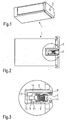
- Fig. 3:
- einen vergrößerten Ausschnitt der in Fig. 2 gezeigten Brennstoffpatrone im Bereich der Anschlusseinrichtung;
- Fig. 4:
- den Ausschnitt von Fig. 3 nach dem Öffnen durch Verbinden mit einem Gegenstück einer Entnahmevorrichtung;
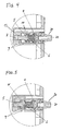
- Fig. 5:
- den Ausschnitt von Fig. 3 und Fig. 4 nach dem Schließen des Sicherheitsventils nach dem Überschreiten einer vorgegebenen Grenztemperatur.
- Fig. 1:
- a schematic 3D view of a fuel cartridge;
- Fig. 2:
- a sectional view of the fuel cartridge shown in Figure 1;
- 3:
- an enlarged detail of the fuel cartridge shown in Figure 2 in the region of the connection device.
- 4:
- the section of Figure 3 after opening by connecting to a counterpart of a removal device.
- Fig. 5:
- the section of Fig. 3 and Fig. 4 after closing the safety valve after exceeding a predetermined limit temperature.
Fig. 1 ist eine schematische dreidimensionale Ansicht einer Brennstoffpatrone 1, die
in die Entnahmeeinrichtung eines Brennstoffzellensystems eingesetzt werden kann,
um dieses mit Brennstoff, beispielsweise Methanol bei einer DMFC (Direct Methanol
Fuel Cell) Brennstoffzelle, zu versorgen. Die Brennstoffpatrone 1 weist eine Anschlusseinrichtung
2 auf, in die eine passend ausgebildete Entnahmeeinrichtung einzuführen
ist, um Brennstoff aus der Patrone zu entnehmen.Fig. 1 is a schematic three-dimensional view of a fuel cartridge 1, the
can be used in the removal device of a fuel cell system,
with this fuel, such as methanol in a DMFC (Direct methanol
Fuel Cell) fuel cell. The fuel cartridge 1 has a
Wie anhand der Schnittansicht von Fig. 2 ersichtlich ist, ist patronenseitig hinter der
Anschlusseinrichtung 2 der Patrone 1 eine Verschlusseinrichtung 3 vorgesehen. Diese
Verschlusseinrichtung 3 umfasst Elemente, die die Patrone fluiddicht verschließen,
wenn keine Brennstoffentnahme erfolgt, und Elemente, die es ermöglichen erlauben,
dass die Patrone 1 durch Verbinden mit dem entsprechend ausgebildeten
Gegenstück 20 der Entnahmeeinrichtung geöffnet werden kann.As can be seen from the sectional view of Fig. 2, is the cartridge side behind the
Zur besseren Erläuterung der Verschlusseinrichtung 3 ist der in Fig. 2 mit einem
Kreis umgebene Ausschnitt im Bereich der Verschlusseinrichtung 3 in Fig. 3 in einer
vergrößerten Darstellung wiedergegeben.For a better explanation of the
Wie Fig. 3 verdeutlicht, ist die Verschlusseinrichtung 3 in einer ersten Bohrung 11
vorgesehen, die verbraucherseitig mit der Anschlusseinrichtung 2 endet. Am gegenüberliegenden
patronenseitigen Ende der ersten Bohrung 11 schließt sich eine koaxiale
zweite Bohrung 12 mit kleinerem Querschnitt an, die an ihrem patronenseitigen
Ende mit einer senkrecht dazu vorgesehenen dritten Bohrung 13 kommuniziert. Letztere
wiederum kommuniziert mit einer vierten Bohrung 14, die parallel zur ersten 11
und zweiten Bohrung 12 verläuft. Für die Fluidverbindung zwischen dem Fluidreservoir
in der Patrone 1 und der ersten Bohrung 11 sorgt ein seitlich in die zweite Bohrung
12 mündender Kanal 9.As FIG. 3 illustrates, the
In der ersten bzw. zweiten Bohrung 11, 12 sind, in der Reihenfolge beginnend von
der Auslassseite, die folgenden Komponenten der Verschlusseinrichtung 3 vorgesehen:
ein Auslassventil 4, eine Druckfeder 6, ein Sicherheitsventil 5, sowie ein fester
Wachspfropfen 7.In the first and
Die Druckfeder 6 ist so zwischen Auslassventil 4 und Sicherheitsventil 5 vorgesehen,
dass sie diese beiden, axial begrenzt bewegbaren Ventile gegenseitig druckbeaufschlagt. The
Die beiden Ventile 4 und 5 umfassen jeweils einen mehr oder weniger axialsymmetrischen
Ventilkörper, der jeweils einen ersten Abschnitt mit einem geringerem (nicht
notwendigerweise konstantem) Durchmesser und einen zweiten Abschnitt mit einem
größeren Durchmesser aufweist, der geringfügig kleiner als der Durchmesser der
ersten Bohrung 11 ist, damit eine saubere und möglichst spielfreie axiale Führung der
Ventile in der ersten Bohrung gewährleistet ist. Der zweite Abschnitt mit dem größeren
Durchmesser weist im abgebildeten bevorzugten Ausführungsbeispiel außerdem
jeweils eine axiale Bohrung, die zur Aufnahme der Druckfeder 6 dient.The two
Die beiden Ventilkörper sind so vorgesehen, dass sich die beiden Abschnitte mit größeren
Durchmesser gegenüberliegen und die beiden axialen Bohrungen jeweils ein
Ende der Druckfeder 6 aufnehmen.The two valve bodies are provided so that the two sections with larger
Diameter opposite and the two axial holes each one
Record end of
Es sei ausdrücklich darauf hingewiesen, dass diese Ventilkörper keine dichtende
Funktion haben. Vielmehr soll zwischen den Ventilkörpern und der Innenwand der
ersten Bohrung 11 das Brennstofffluid in axialer Richtung strömen können. Um eine
solche Strömung zu ermöglichen oder zu verbessern, können daher im Umfangsbereich
der Ventilkörper Nuten vorgesehen sein (nicht gezeigt). Die dichtende Funktion
wird durch O-Ringe erfüllt, die über den Abschnitt mit geringerem Durchmesser gestülpt
sind und an der Stirnfläche anliegen, die am Übergang vom Abschnitt mit geringerem
Durchmesser zum Abschnitt mit größerem Durchmesser ausgebildet ist.It should be expressly understood that these valve bodies are not sealing
Have function. Rather, between the valve bodies and the inner wall of the
Beim in Fig. 3 skizzierten Zustand liegt der O-Ring des Auslassventils 4 zudem an
einem auslassseitigen Anschlag an, der durch die patronenseitig Stirnseite eines
ringförmigen Einsatzkörpers 8 gebildet wird, welcher in das Auslassende 2 eingepasst
ist, wodurch die Patrone 1 fluiddicht verschlossen wird.When sketched in Fig. 3 state of the O-ring of the
Der Einsatzkörper 8 weist an seiner Innenseite eine radial verlaufende Nut auf, in die
ein weiterer O-Ring eingepasst ist. Dieser O-Ring gewährleistet, dass das Gegenstück
20 einer Entnahmeeinrichtung in die Anschlusseinrichtung 2 unter Ausbildung
einer fluiddichten Verbindung eingeführt werden kann.The
Der Wachspfropfen 7, der einen patronenseitiger Abschnitt der zweiten Bohrung 12 ausfüllt, dient als patronenseitiger Anschlag (Wideriager) für das geöffnete Sicherheitsventil
5 (Als patronenseitiger Anschlag für das geschlossene Sicherheitsventil 5
dient die ringförmige Stirnfläche der ersten Bohrung 11, die durch die zweite Bohrung
12 durchstoßen wird; vgl. auch Fig. 5).The
Die dritte und vierte Bohrung bilden einen Ausweichkanal 13, 14, in den das geschmolzene
Wachs nach dem Überschreiten der Schmelztemperatur unter Einwirken
des axial in Richtung Patroneninneres verschobenen Sicherheitsventils 5 verdrängt
wird. Die Wachsart und damit die Schmelztemperatur wird entsprechend der erwünschten
Grenztemperatur ausgewählt. Der Ausweichkanal 13, 14 muss ausreichend
groß dimensioniert sein, um das gesamte geschmolzene Wachs aufnehmen
zu können. Im vorliegenden Ausführungsbeispiel erstreckt sich die vierte Bohrung 14
sogar bis zur Außenseite der Patrone und ist dort offen oder mit einem Sichtfenster
verschlossen. Dies ermöglicht es, visuell zu überprüften, ob der originale feste
Wachspfropfen 7 noch intakt ist, oder ob die Grenztemperatur überschritten ist bzw.
zwischenzeitlich überschritten wurde und somit Wachs in den Ausweichkanal 13, 14
verdrängt wurde.The third and fourth holes form an
Wenn - wie in Fig. 3 gezeigt - keine Entnahmeeinrichtung vorgesehen ist und eine
vorgegebene Grenztemperatur noch nicht überschritten wurde, ist das Auslassventil
4 geschlossen und das Sicherheitsventil 5 offen, so dass Brennstoff aus dem
Patroneninneren über den Kanal 9 in den Abschnitt der ersten Bohrung 11 strömen
kann, der durch das Auslassventil 4 gegenüber der Anschlusseinrichtung 2
abgedichtet wird, aber nicht nach außen gelangen kann. D.h., die
Verschlusseinrichtung 3 ist insgesamt geschlossen.If - as shown in Fig. 3 - no removal device is provided and a
specified limit temperature has not been exceeded, is the
Fig. 4 zeigt nun, wie unter Verwendung eines zur Anschlusseinrichtung 2 der Patrone
1 passenden Gegenstücks 20 einer Entnahmevorrichtung Brennstoff aus der Patrone
1 entnommen werden kann.Fig. 4 now shows how using one of the
Durch Einführen des Gegenstücks 20 wird das Auslassventil 4 axial in Richtung Patroneninneres
verschoben, so dass der O-Ring des Auslassventil den Innenbereich
der ersten Bohrung 11 nicht mehr gegen ihren äußeren Bereich (im Bereich der Anschlusseinrichtung
2) abdichtet, d.h. das Auslassventil 4 wird geöffnet. Das Gegenstück
20 liegt in seinem zylindrische Umfangsbereich dichtend am O-Ring des
Einsatzkörpers 8, so dass Brennstoff ausschließlich über eine Kanüle 21 im Gegenstück
20 abgeführt werden kann.By inserting the
Der Pressdruck dieses O-Rings auf den Umfangsbereich des Gegenstücks 20 kann
ausreichend sein, um eine stabile mechanische Verbindung zwischen Patrone 1 und
Gegenstück 20 zu gewährleisten. Es können aber auch nicht gezeigte Einrichtungen
für eine mechanische Arretierung des Gegenstücks 20 an der Patrone 1 vorgesehen
werden.The pressing pressure of this O-ring on the peripheral portion of the
Die analog zu Fig. 4 ausgeführte Fig. 5 zeigt nun die Situation, die vorliegt, wenn die vorgegebene Grenztemperatur überschritten wird (oder wurde).FIG. 5, which is executed analogously to FIG. 4, now shows the situation which exists when the specified limit temperature is exceeded (or was).
Der in der zweiten Bohrung 12 vorgesehene Wachspfropfen 7 ist geschmolzen und
das geschmolzene Wachs 7' wurde durch das in der zweiten Bohrung 12 geführte
Ende der Körpers der Sicherheitsventils 5 unter Expansion der Druckfeder 6 in den
Ausweichkanal 13, 14 verdrängt. Damit entfällt der Wachspfropfen 7 als patronenseitiger
Anschlag für das geöffnete Sicherheitsventil 5 und der O-Ring des Sicherheitsventil
5 wird an die ringförmige Stirnfläche der ersten Bohrung 11, die durch die zweite
Bohrung 12 durchstoßen wird, unter Wirkung der Druckfeder 6 gepresst. Dadurch
wird die Fluidverbindung zwischen dem Kanal 9 und der ersten Bohrung 11 unterbrochen:
das Sicherheitsventil 5 - und damit auch die gesamte Verschlusseinrichtung 3 -
ist geschlossen und eine Fluidentnahme aus dem Brennstoffreservoir in der Patrone
1 ist nicht mehr möglich (eine etwaige Restmenge im Bereich der ersten Bohrung 11
kann vernachlässigt werden).The measures provided for in the
Die Dimension des Ausweichkanals 13, 14 und die Menge an Wachs 7 werden vorzugsweise
so gewählt, dass das schmelzende oder geschmolzene Wachs 7' in einem
Sichtfenster am Ende der vierten Bohrung 14 eine farbige Markierung bewirkt, die
dem Nutzer die Nichtverwendbarkeit der Patrone 1 signalisiert. Damit kann auch ein
"Erziehungseffekt" für den Benutzer ausgeübt werden.The dimension of the
Für Anwendungen bei DMFC-Brennstoffzellen ist die mit Methanol zu füllende Brennstoffpatrone 1 so gestaltet, dass der äußere Aufbau einem gewissen Innendruck (vorzugsweise 1-2 bar Überdruck) widersteht. For DMFC fuel cell applications, the fuel cartridge to be filled with methanol 1 designed so that the external structure of a certain internal pressure (preferably 1-2 bar overpressure) withstands.
Obwohl die Beschreibung der Erfindung anhand eines Ausführungsbeispiels mit einem irreversiblen Thermosicherung erfolgte, umfasst die Erfindung auch reversibel ausgebildete Thermosicherungen, die z.B. Bimetallstreifen verwenden, welche sich nahezu reversibel gegenüber Temperaturänderungen verhalten. Alternative Ausführungsformen bestehen aus einer thermisch aktivierten, mechanischen Sperre im Anschlussbereich, die den mechanischen Anschluss der Tankpatrone unterbindet.Although the description of the invention with reference to an embodiment with a irreversible thermal fuse, the invention also includes reversible formed thermal fuses, e.g. Use bimetallic strips, which are themselves behave almost reversibly with respect to temperature changes. Alternative embodiments consist of a thermally activated, mechanical barrier in the connection area, which prevents the mechanical connection of the fuel cartridge.
Austauschbare Brennstoffpatronen (Tankpatronen) unterliegen einem enormen Kostendruck. Mit der vorliegenden Erfindung, die konstruktiv einfach realisierbar ist und die Verwendung äußerst preisgünstiger Materialien ermöglicht, wird ein wirksamer "Schutz bei hohen Temperaturen" ermöglicht, ohne dass dadurch die Herstellungskosten für eine Brennstoffpatrone signifikant steigen.Replaceable fuel cartridges (fuel cartridges) are subject to enormous cost pressure. With the present invention, which is structurally easy to implement and The use of extremely low-cost materials becomes more effective "Protection at high temperatures" allows, without affecting the manufacturing costs increase significantly for a fuel cartridge.
Claims (10)
Priority Applications (4)
| Application Number | Priority Date | Filing Date | Title |
|---|---|---|---|
| DE50305501T DE50305501D1 (en) | 2003-08-25 | 2003-08-25 | Fuel container with thermal fuse |
| EP03019184A EP1510752B1 (en) | 2003-08-25 | 2003-08-25 | Fuel vessel with overheating safety device |
| AT03019184T ATE343761T1 (en) | 2003-08-25 | 2003-08-25 | FUEL TANK WITH THERMAL FUSE |
| PCT/EP2004/008993 WO2005022029A1 (en) | 2003-08-25 | 2004-08-11 | Fuel container comprising a thermal safety device |
Applications Claiming Priority (1)
| Application Number | Priority Date | Filing Date | Title |
|---|---|---|---|
| EP03019184A EP1510752B1 (en) | 2003-08-25 | 2003-08-25 | Fuel vessel with overheating safety device |
Publications (2)
| Publication Number | Publication Date |
|---|---|
| EP1510752A1 true EP1510752A1 (en) | 2005-03-02 |
| EP1510752B1 EP1510752B1 (en) | 2006-10-25 |
Family
ID=34089601
Family Applications (1)
| Application Number | Title | Priority Date | Filing Date |
|---|---|---|---|
| EP03019184A Expired - Lifetime EP1510752B1 (en) | 2003-08-25 | 2003-08-25 | Fuel vessel with overheating safety device |
Country Status (4)
| Country | Link |
|---|---|
| EP (1) | EP1510752B1 (en) |
| AT (1) | ATE343761T1 (en) |
| DE (1) | DE50305501D1 (en) |
| WO (1) | WO2005022029A1 (en) |
Cited By (2)
| Publication number | Priority date | Publication date | Assignee | Title |
|---|---|---|---|---|
| DE102007017429A1 (en) * | 2007-04-13 | 2008-10-16 | GM Global Technology Operations, Inc., Detroit | Safety arrangement for gas tank of a motor vehicle |
| DE102010011878A1 (en) * | 2010-03-18 | 2011-09-22 | Hydac Technology Gmbh | Safety device for gas pressure loaded containers |
Citations (6)
| Publication number | Priority date | Publication date | Assignee | Title |
|---|---|---|---|---|
| GB1402531A (en) * | 1971-02-01 | 1975-08-13 | Gehler J J | Mechanical cut-out device for combustion engines |
| GB2209200A (en) * | 1987-08-28 | 1989-05-04 | Thorn Emi Flow Measurement Ltd | Thermal cut-off valve |
| US5787918A (en) * | 1994-11-04 | 1998-08-04 | Kosan Teknova A/S | Reduction valve and gas container valve for a bottle for liquified gas |
| US6155285A (en) * | 1999-08-30 | 2000-12-05 | Hsiao; Chi-Chen | Gas safety valve |
| US20030041899A1 (en) * | 2001-09-04 | 2003-03-06 | The Coleman Company, Inc. | Pressurized gas canister |
| FR2832205A1 (en) * | 2001-11-14 | 2003-05-16 | Briffault Sa | Tap for gas container comprises valve activated by plastic lever which melts at pre-specified temperature to push rod which puts valve in closed position on seat |
-
2003
- 2003-08-25 EP EP03019184A patent/EP1510752B1/en not_active Expired - Lifetime
- 2003-08-25 AT AT03019184T patent/ATE343761T1/en not_active IP Right Cessation
- 2003-08-25 DE DE50305501T patent/DE50305501D1/en not_active Expired - Lifetime
-
2004
- 2004-08-11 WO PCT/EP2004/008993 patent/WO2005022029A1/en active Application Filing
Patent Citations (6)
| Publication number | Priority date | Publication date | Assignee | Title |
|---|---|---|---|---|
| GB1402531A (en) * | 1971-02-01 | 1975-08-13 | Gehler J J | Mechanical cut-out device for combustion engines |
| GB2209200A (en) * | 1987-08-28 | 1989-05-04 | Thorn Emi Flow Measurement Ltd | Thermal cut-off valve |
| US5787918A (en) * | 1994-11-04 | 1998-08-04 | Kosan Teknova A/S | Reduction valve and gas container valve for a bottle for liquified gas |
| US6155285A (en) * | 1999-08-30 | 2000-12-05 | Hsiao; Chi-Chen | Gas safety valve |
| US20030041899A1 (en) * | 2001-09-04 | 2003-03-06 | The Coleman Company, Inc. | Pressurized gas canister |
| FR2832205A1 (en) * | 2001-11-14 | 2003-05-16 | Briffault Sa | Tap for gas container comprises valve activated by plastic lever which melts at pre-specified temperature to push rod which puts valve in closed position on seat |
Cited By (3)
| Publication number | Priority date | Publication date | Assignee | Title |
|---|---|---|---|---|
| DE102007017429A1 (en) * | 2007-04-13 | 2008-10-16 | GM Global Technology Operations, Inc., Detroit | Safety arrangement for gas tank of a motor vehicle |
| DE102010011878A1 (en) * | 2010-03-18 | 2011-09-22 | Hydac Technology Gmbh | Safety device for gas pressure loaded containers |
| US10000318B2 (en) | 2010-03-18 | 2018-06-19 | Hydac Technology Gmbh | Safety device against excess temperature |
Also Published As
| Publication number | Publication date |
|---|---|
| ATE343761T1 (en) | 2006-11-15 |
| EP1510752B1 (en) | 2006-10-25 |
| DE50305501D1 (en) | 2006-12-07 |
| WO2005022029A1 (en) | 2005-03-10 |
Similar Documents
| Publication | Publication Date | Title |
|---|---|---|
| EP2054691B1 (en) | Bypass valve for a cooler connected downstream of a hydraulic unit | |
| DE60309339T2 (en) | HEAT AND PRESSURE RELIEF COMBINATION VALVE | |
| DE102006003271A1 (en) | Thermostatic valve for connecting an automatic transmission to an oil cooler | |
| DE102016008442A1 (en) | tank valve | |
| EP3521584B1 (en) | Compensation container for coolant circuits with different temperature level and pressure addition | |
| EP2796767B1 (en) | Safety device for installation in a gas supply installation, in particular in an acetylene supply installation | |
| EP1745231B1 (en) | Coupling device for a compressed gas cylinder | |
| EP1510752B1 (en) | Fuel vessel with overheating safety device | |
| DE102014003586A1 (en) | Fuel tank, motor vehicle | |
| DE102013002777A1 (en) | Device for storing gas under high pressure, particularly for storing hydrogen in vehicle using hydrogen as fuel, has trip unit with pyrocharge for indirect triggering of safety blow-off unit | |
| EP2453804B1 (en) | Compressed gas operated instrument, in particular surgical instrument | |
| WO2019206715A1 (en) | Fusible link, gas tank, and method for assembling a fusible link and for installing same in a gas tank | |
| CH634134A5 (en) | PRESSURE VALVE. | |
| DE3204309A1 (en) | DISPLAY DEVICE FOR MONITORING THE EXCEEDING OF A PARTICULAR PRESSURE DIFFERENCE IN A PRESSURE FLUID SYSTEM AFTER REACHING A PARTICULAR FLUID TEMPERATURE | |
| DE10361453B3 (en) | Plug for sealing off working chambers in especially hydrodynamic machines has sealing component comprising sleeve with through-hole in which is fitted bolt, with fusible safety element interconnecting sleeve and bolt | |
| EP2275037B1 (en) | Instrument operated using pressurised gas | |
| DE102014106639B4 (en) | Pressure relief valve | |
| DE10361440B4 (en) | Hydrodynamic fluid machine with closure with thermal safety function | |
| DE2054638C3 (en) | Throttle valve | |
| DE8209703U1 (en) | HOSE BREAKAGE PROTECTION FOR GAS SYSTEMS | |
| DE19813307B4 (en) | Shut-off valve with a ball valve | |
| DE2717820A1 (en) | HEAT SAFETY VALVE | |
| DE19625405C2 (en) | Device and method for cooling heated materials in solid or liquid state, in particular melting, slagging and the like | |
| DE19747496C1 (en) | Gas pipe closure with ball valve | |
| DE8536664U1 (en) | Pressure reducing device |
Legal Events
| Date | Code | Title | Description |
|---|---|---|---|
| PUAI | Public reference made under article 153(3) epc to a published international application that has entered the european phase |
Free format text: ORIGINAL CODE: 0009012 |
|
| 17P | Request for examination filed |
Effective date: 20041014 |
|
| AK | Designated contracting states |
Kind code of ref document: A1 Designated state(s): AT BE BG CH CY CZ DE DK EE ES FI FR GB GR HU IE IT LI LU MC NL PT RO SE SI SK TR |
|
| AX | Request for extension of the european patent |
Extension state: AL LT LV MK |
|
| RAP1 | Party data changed (applicant data changed or rights of an application transferred) |
Owner name: SFC SMART FUEL CELL GMBH |
|
| RAP1 | Party data changed (applicant data changed or rights of an application transferred) |
Owner name: SFC SMART FUEL CELL AG |
|
| AKX | Designation fees paid |
Designated state(s): AT BE BG CH CY CZ DE DK EE ES FI FR GB GR HU IE IT LI LU MC NL PT RO SE SI SK TR |
|
| GRAP | Despatch of communication of intention to grant a patent |
Free format text: ORIGINAL CODE: EPIDOSNIGR1 |
|
| GRAS | Grant fee paid |
Free format text: ORIGINAL CODE: EPIDOSNIGR3 |
|
| GRAA | (expected) grant |
Free format text: ORIGINAL CODE: 0009210 |
|
| AK | Designated contracting states |
Kind code of ref document: B1 Designated state(s): AT BE BG CH CY CZ DE DK EE ES FI FR GB GR HU IE IT LI LU MC NL PT RO SE SI SK TR |
|
| PG25 | Lapsed in a contracting state [announced via postgrant information from national office to epo] |
Ref country code: IT Free format text: LAPSE BECAUSE OF FAILURE TO SUBMIT A TRANSLATION OF THE DESCRIPTION OR TO PAY THE FEE WITHIN THE PRESCRIBED TIME-LIMIT;WARNING: LAPSES OF ITALIAN PATENTS WITH EFFECTIVE DATE BEFORE 2007 MAY HAVE OCCURRED AT ANY TIME BEFORE 2007. THE CORRECT EFFECTIVE DATE MAY BE DIFFERENT FROM THE ONE RECORDED. Effective date: 20061025 Ref country code: SI Free format text: LAPSE BECAUSE OF FAILURE TO SUBMIT A TRANSLATION OF THE DESCRIPTION OR TO PAY THE FEE WITHIN THE PRESCRIBED TIME-LIMIT Effective date: 20061025 Ref country code: NL Free format text: LAPSE BECAUSE OF FAILURE TO SUBMIT A TRANSLATION OF THE DESCRIPTION OR TO PAY THE FEE WITHIN THE PRESCRIBED TIME-LIMIT Effective date: 20061025 Ref country code: SK Free format text: LAPSE BECAUSE OF FAILURE TO SUBMIT A TRANSLATION OF THE DESCRIPTION OR TO PAY THE FEE WITHIN THE PRESCRIBED TIME-LIMIT Effective date: 20061025 Ref country code: IE Free format text: LAPSE BECAUSE OF FAILURE TO SUBMIT A TRANSLATION OF THE DESCRIPTION OR TO PAY THE FEE WITHIN THE PRESCRIBED TIME-LIMIT Effective date: 20061025 Ref country code: RO Free format text: LAPSE BECAUSE OF FAILURE TO SUBMIT A TRANSLATION OF THE DESCRIPTION OR TO PAY THE FEE WITHIN THE PRESCRIBED TIME-LIMIT Effective date: 20061025 Ref country code: CZ Free format text: LAPSE BECAUSE OF FAILURE TO SUBMIT A TRANSLATION OF THE DESCRIPTION OR TO PAY THE FEE WITHIN THE PRESCRIBED TIME-LIMIT Effective date: 20061025 Ref country code: FI Free format text: LAPSE BECAUSE OF FAILURE TO SUBMIT A TRANSLATION OF THE DESCRIPTION OR TO PAY THE FEE WITHIN THE PRESCRIBED TIME-LIMIT Effective date: 20061025 |
|
| REG | Reference to a national code |
Ref country code: GB Ref legal event code: FG4D Free format text: NOT ENGLISH |
|
| REG | Reference to a national code |
Ref country code: CH Ref legal event code: EP |
|
| REG | Reference to a national code |
Ref country code: IE Ref legal event code: FG4D Free format text: LANGUAGE OF EP DOCUMENT: GERMAN |
|
| REF | Corresponds to: |
Ref document number: 50305501 Country of ref document: DE Date of ref document: 20061207 Kind code of ref document: P |
|
| PG25 | Lapsed in a contracting state [announced via postgrant information from national office to epo] |
Ref country code: SE Free format text: LAPSE BECAUSE OF FAILURE TO SUBMIT A TRANSLATION OF THE DESCRIPTION OR TO PAY THE FEE WITHIN THE PRESCRIBED TIME-LIMIT Effective date: 20070125 Ref country code: BG Free format text: LAPSE BECAUSE OF FAILURE TO SUBMIT A TRANSLATION OF THE DESCRIPTION OR TO PAY THE FEE WITHIN THE PRESCRIBED TIME-LIMIT Effective date: 20070125 Ref country code: DK Free format text: LAPSE BECAUSE OF FAILURE TO SUBMIT A TRANSLATION OF THE DESCRIPTION OR TO PAY THE FEE WITHIN THE PRESCRIBED TIME-LIMIT Effective date: 20070125 |
|
| PG25 | Lapsed in a contracting state [announced via postgrant information from national office to epo] |
Ref country code: ES Free format text: LAPSE BECAUSE OF FAILURE TO SUBMIT A TRANSLATION OF THE DESCRIPTION OR TO PAY THE FEE WITHIN THE PRESCRIBED TIME-LIMIT Effective date: 20070205 |
|
| GBT | Gb: translation of ep patent filed (gb section 77(6)(a)/1977) |
Effective date: 20070125 |
|
| PG25 | Lapsed in a contracting state [announced via postgrant information from national office to epo] |
Ref country code: PT Free format text: LAPSE BECAUSE OF FAILURE TO SUBMIT A TRANSLATION OF THE DESCRIPTION OR TO PAY THE FEE WITHIN THE PRESCRIBED TIME-LIMIT Effective date: 20070326 |
|
| NLV1 | Nl: lapsed or annulled due to failure to fulfill the requirements of art. 29p and 29m of the patents act | ||
| ET | Fr: translation filed | ||
| REG | Reference to a national code |
Ref country code: IE Ref legal event code: FD4D |
|
| PLBE | No opposition filed within time limit |
Free format text: ORIGINAL CODE: 0009261 |
|
| STAA | Information on the status of an ep patent application or granted ep patent |
Free format text: STATUS: NO OPPOSITION FILED WITHIN TIME LIMIT |
|
| 26N | No opposition filed |
Effective date: 20070726 |
|
| BERE | Be: lapsed |
Owner name: SFC SMART FUEL CELL A.G. Effective date: 20070831 |
|
| REG | Reference to a national code |
Ref country code: CH Ref legal event code: PL |
|
| PG25 | Lapsed in a contracting state [announced via postgrant information from national office to epo] |
Ref country code: GR Free format text: LAPSE BECAUSE OF FAILURE TO SUBMIT A TRANSLATION OF THE DESCRIPTION OR TO PAY THE FEE WITHIN THE PRESCRIBED TIME-LIMIT Effective date: 20070126 Ref country code: LI Free format text: LAPSE BECAUSE OF NON-PAYMENT OF DUE FEES Effective date: 20070831 Ref country code: CH Free format text: LAPSE BECAUSE OF NON-PAYMENT OF DUE FEES Effective date: 20070831 Ref country code: MC Free format text: LAPSE BECAUSE OF NON-PAYMENT OF DUE FEES Effective date: 20070831 |
|
| PG25 | Lapsed in a contracting state [announced via postgrant information from national office to epo] |
Ref country code: BE Free format text: LAPSE BECAUSE OF NON-PAYMENT OF DUE FEES Effective date: 20070831 |
|
| PG25 | Lapsed in a contracting state [announced via postgrant information from national office to epo] |
Ref country code: AT Free format text: LAPSE BECAUSE OF NON-PAYMENT OF DUE FEES Effective date: 20070825 |
|
| PG25 | Lapsed in a contracting state [announced via postgrant information from national office to epo] |
Ref country code: EE Free format text: LAPSE BECAUSE OF FAILURE TO SUBMIT A TRANSLATION OF THE DESCRIPTION OR TO PAY THE FEE WITHIN THE PRESCRIBED TIME-LIMIT Effective date: 20061025 |
|
| PG25 | Lapsed in a contracting state [announced via postgrant information from national office to epo] |
Ref country code: CY Free format text: LAPSE BECAUSE OF FAILURE TO SUBMIT A TRANSLATION OF THE DESCRIPTION OR TO PAY THE FEE WITHIN THE PRESCRIBED TIME-LIMIT Effective date: 20061025 Ref country code: LU Free format text: LAPSE BECAUSE OF NON-PAYMENT OF DUE FEES Effective date: 20070825 |
|
| PG25 | Lapsed in a contracting state [announced via postgrant information from national office to epo] |
Ref country code: HU Free format text: LAPSE BECAUSE OF FAILURE TO SUBMIT A TRANSLATION OF THE DESCRIPTION OR TO PAY THE FEE WITHIN THE PRESCRIBED TIME-LIMIT Effective date: 20070426 Ref country code: TR Free format text: LAPSE BECAUSE OF FAILURE TO SUBMIT A TRANSLATION OF THE DESCRIPTION OR TO PAY THE FEE WITHIN THE PRESCRIBED TIME-LIMIT Effective date: 20061025 |
|
| REG | Reference to a national code |
Ref country code: DE Ref legal event code: R082 Ref document number: 50305501 Country of ref document: DE Representative=s name: GRUENECKER, KINKELDEY, STOCKMAIR & SCHWANHAEUS, DE Effective date: 20110706 |
|
| REG | Reference to a national code |
Ref country code: FR Ref legal event code: PLFP Year of fee payment: 14 |
|
| REG | Reference to a national code |
Ref country code: FR Ref legal event code: PLFP Year of fee payment: 15 |
|
| REG | Reference to a national code |
Ref country code: FR Ref legal event code: PLFP Year of fee payment: 16 |
|
| PGFP | Annual fee paid to national office [announced via postgrant information from national office to epo] |
Ref country code: GB Payment date: 20220824 Year of fee payment: 20 Ref country code: DE Payment date: 20220825 Year of fee payment: 20 |
|
| PGFP | Annual fee paid to national office [announced via postgrant information from national office to epo] |
Ref country code: FR Payment date: 20220824 Year of fee payment: 20 |
|
| REG | Reference to a national code |
Ref country code: DE Ref legal event code: R071 Ref document number: 50305501 Country of ref document: DE |
|
| REG | Reference to a national code |
Ref country code: GB Ref legal event code: PE20 Expiry date: 20230824 |
|
| PG25 | Lapsed in a contracting state [announced via postgrant information from national office to epo] |
Ref country code: GB Free format text: LAPSE BECAUSE OF EXPIRATION OF PROTECTION Effective date: 20230824 |