EP1510699B1 - Procédé et dispositif pour commuter un flux - Google Patents
Procédé et dispositif pour commuter un flux Download PDFInfo
- Publication number
- EP1510699B1 EP1510699B1 EP20040018691 EP04018691A EP1510699B1 EP 1510699 B1 EP1510699 B1 EP 1510699B1 EP 20040018691 EP20040018691 EP 20040018691 EP 04018691 A EP04018691 A EP 04018691A EP 1510699 B1 EP1510699 B1 EP 1510699B1
- Authority
- EP
- European Patent Office
- Prior art keywords
- slide
- housing
- diameter
- sliding ring
- valve
- Prior art date
- Legal status (The legal status is an assumption and is not a legal conclusion. Google has not performed a legal analysis and makes no representation as to the accuracy of the status listed.)
- Not-in-force
Links
Images


Classifications
-
- F—MECHANICAL ENGINEERING; LIGHTING; HEATING; WEAPONS; BLASTING
- F15—FLUID-PRESSURE ACTUATORS; HYDRAULICS OR PNEUMATICS IN GENERAL
- F15B—SYSTEMS ACTING BY MEANS OF FLUIDS IN GENERAL; FLUID-PRESSURE ACTUATORS, e.g. SERVOMOTORS; DETAILS OF FLUID-PRESSURE SYSTEMS, NOT OTHERWISE PROVIDED FOR
- F15B13/00—Details of servomotor systems ; Valves for servomotor systems
- F15B13/02—Fluid distribution or supply devices characterised by their adaptation to the control of servomotors
- F15B13/04—Fluid distribution or supply devices characterised by their adaptation to the control of servomotors for use with a single servomotor
- F15B13/0401—Valve members; Fluid interconnections therefor
- F15B13/0402—Valve members; Fluid interconnections therefor for linearly sliding valves, e.g. spool valves
- F15B13/0403—Valve members; Fluid interconnections therefor for linearly sliding valves, e.g. spool valves a secondary valve member sliding within the main spool, e.g. for regeneration flow
-
- Y—GENERAL TAGGING OF NEW TECHNOLOGICAL DEVELOPMENTS; GENERAL TAGGING OF CROSS-SECTIONAL TECHNOLOGIES SPANNING OVER SEVERAL SECTIONS OF THE IPC; TECHNICAL SUBJECTS COVERED BY FORMER USPC CROSS-REFERENCE ART COLLECTIONS [XRACs] AND DIGESTS
- Y10—TECHNICAL SUBJECTS COVERED BY FORMER USPC
- Y10T—TECHNICAL SUBJECTS COVERED BY FORMER US CLASSIFICATION
- Y10T137/00—Fluid handling
- Y10T137/8593—Systems
- Y10T137/86493—Multi-way valve unit
- Y10T137/86574—Supply and exhaust
- Y10T137/86582—Pilot-actuated
-
- Y—GENERAL TAGGING OF NEW TECHNOLOGICAL DEVELOPMENTS; GENERAL TAGGING OF CROSS-SECTIONAL TECHNOLOGIES SPANNING OVER SEVERAL SECTIONS OF THE IPC; TECHNICAL SUBJECTS COVERED BY FORMER USPC CROSS-REFERENCE ART COLLECTIONS [XRACs] AND DIGESTS
- Y10—TECHNICAL SUBJECTS COVERED BY FORMER USPC
- Y10T—TECHNICAL SUBJECTS COVERED BY FORMER US CLASSIFICATION
- Y10T137/00—Fluid handling
- Y10T137/8593—Systems
- Y10T137/86493—Multi-way valve unit
- Y10T137/86574—Supply and exhaust
- Y10T137/86622—Motor-operated
- Y10T137/8663—Fluid motor
Definitions
- the invention relates to a method and apparatus for rapid switching of a liquid or gaseous medium in a hydraulic or pneumatic route by means of a pump depending on the pilot pressure either in a reservoir or in the hydraulic / pneumatic route using a switching valve.
- the control of, for example, an oil flow in a hydraulic path takes place primarily via at least one pump, the direction and the flow rate of which are arranged in the hydraulic path, correspondingly pilot operated valves.
- a balance of hydraulic amount is realized via a reservoir, so that corresponding valves or valve assemblies are provided to realize a flood switch from the pump either in the hydraulic route or in the reservoir, such as from EP-A-1 279 870 is known.
- a check valve with a parallel throttle section wherein a correspondingly constructive throttle insert operates in this throttle section as a flow regulator.
- a plurality of valves of different function such as a non-return and a relief valve function, are coupled together as a pilot-operated pressure control valve with a check valve.
- the spring chamber of the pressure regulating piston is connected via a further throttle bore in the pressure regulating piston itself with a pressure or pump connection. If the static pressure rises above the set value of the pressure valve, it is opened, allowing hydraulic fluid to drain to the reservoir. This drain creates a pressure drop in the spring chamber of the pressure regulating piston, whereby the closing force of the spring is released and the pressure regulating piston of the check valve opens the way to the reservoir.
- valve spool If the valve spool is subjected to a pressure which is higher than the two spring forces in the spring chambers, the valve spool lifts from its valve seat fixed to the housing and closes the control port.
- the other closure piece works as a pressure regulating piston and communicates with the other housing-side connections, which are released or opened during this process accordingly.
- valve spool covers during the switching for a certain time a defined area in the housing, which must be technical, so that the hydraulic route can not be connected directly to the reservoir.
- the pressure that builds up before the pump is limited by the pressure relief valve, which is located between the hydraulic section and the pump.
- the object of the invention is to switch the fluid from a pump pilot pressure dependent in different line connections so that the time required for this purpose shortened and the switching is realized by means of only one valve while the size of the valve undergoes only an insignificant change.
- this object is initially achieved in that the slide has a first slide element and a second slide element, which are accelerated independently of each other at least during a time interval of the switching process.
- This acceleration serves to shorten the switching process in order to reduce the pressure increase occurring during the switching before the pump as quickly as possible, which u. a. extends the life of the pump.
- the axial movement of the slide in the valve is superimposed on a further axial movement, resulting in a resulting movement, which is the result of the addition of equal and opposite forces, these forces acting simultaneously or with a time delay on the slide during the switching operation.
- a pump is connected either to a fluidic path or to a reservoir by means of a pilot-pressure-dependent three-way valve.
- a pilot-pressure-dependent three-way valve which contains a two-part slide with a first slide element and a second slide element and that the housing of the valve has further connections to the pump, which connect to the existing connections in the axial direction and are spaced from both these and from each other.
- the wall thickness of the housing like a paragraph and remains the same for the rest of the housing part.
- the resulting at the shoulder radial annular surface also forms the abutment surface for the slider guided in the housing.
- the object is achieved in that the slide has an incision in front of its pressure spring end, which reaches the diameter of the slide again in two correspondingly wide steps in the direction of this end and with a further outermost stage adapts to the inner diameter of the housing.
- This step-like design of the incision has the advantage that simultaneously defined stops can be realized in this way.
- the structural design of the housing suggests that the radial annular surface created by the outermost step of the slide forms the return surface and advantageously limits the travel of the pressure spring with the stop surface.
- the slide is provided in the radial direction with a centrally arranged through hole
- the diameter of this hole is equal to the diameter of the two additional pump connections to choose to establish a secure connection between the pump and slide can and to achieve no pressure losses.
- the holes provided in the slide which are connected at right angles to a line, are used together with the step-like recess for receiving a defined volume of oil, which can be carried out in case of need by pressurization or pressure relief movements of components.
- the existing in the blind hole pin within the blind hole is moved either towards the housing wall or in the direction of drilling. It is advantageous that it has a certain length in order to be able to center also for the slide in the housing.
- a further advantageous embodiment of the invention provides that functionally, the width of the innermost stage of the incision is defined by the distance between the outer wall of the diameter of the through hole to the shoulder of the subsequent second stage and the width of the second stage of the sum of the diameter the two additional pump connections and their distance from each other.
- the width of the second stage of the incision adjoins that of the innermost and goes beyond the heel-like reduction of the wall thickness of the housing.
- an additional pressure chamber is formed, which also serves to influence the axial movement of the slide.
- a sliding ring is applied to the innermost stage of the incision, which can move axially on this.
- the mass of the slider is divided into two sub-masses. The mutually operatively connected masses can thus be acted upon with different, large forces whose direction may also be different.
- the outer diameter of the sliding ring corresponds to the inner diameter of the housing, d. h., that both abut each other. This ensures that, on the one hand, the respective additional pump connection is closed and, on the other hand, the pressure built up in the second pressure chamber can not be reduced in an uncontrolled manner.
- the width of the sliding ring results from the difference between the width of the innermost step width and the diameter of the connection. This ensures that an additional pump connection is always open when the sliding ring is in one of its end positions at the innermost stage.
- Another advantage is that the surface roughness of the outer and inner diameter of the sliding ring is different. It is particularly advantageous if the roughness of the surface at the outer diameter of the sliding ring is higher than at the inner diameter. As a result, a static friction between the surface of the sliding ring and the surface of the inner diameter of the housing is achieved, which is exploited to achieve a delay in reversing the direction of movement of the slider.
- the slider and sliding ring is made of metallic material.
- both can equally well consist of non-metallic material and plastic material.
- the two components may have different materials. This depends on the particular application.
- FIG. 1 is the basic structure and operation of the invention in a hydraulic route visible.
- a pilot pressure which is performed by a piston.
- the closure member or slide present in the valve is moved so that the desired lines are connected to each other.
- Fig. 1 is essentially a connection from the pump to the hydraulic path recognizable, which is interrupted by the closing body of the valve at falling pilot pressure to make the connection hydraulic route - reservoir.
- the slide in the valve housing covers a certain area, so that in this connection to two ports can not be produced, but always a housing connection is closed.
- this overlap area is technically conditioned to exclude a connection of the hydraulic route to the reservoir.
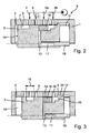
- the valve 8 consisting essentially of a housing 1 and a slide 2, which is held by a compression spring 11 in a certain position, inter alia.
- the housing 1, whose wall thickness is reduced step-like to form a paragraph pressure spring side, has 6 holes or connection options for corresponding lines. In this case, a connection for the introduction of hydraulic oil for acting on the pressing surface 14 of the slider 2 with a certain pressure, the pilot pressure is used.
- the further holes are provided for connections to a pump 4, 4a and 4b, to a reservoir 5 and to the hydraulic path 6.
- the slider 2 is provided at a distance from the pressing surface 14 with a circumferential groove 7, the width of which results from the distance between two adjacent ports plus their diameter. This ensures that the groove 7 in the axial movement of the slider 2 in each case two of the adjacent terminals 6, 4, 5, the distance between the groove 7 of the pressing surface 14 depends on the stop of the slider 2 on the housing 1, resulting from the Impact of the return surface 12 of the slider 2 on the stop surface 9 of the housing 1 results.
- the connections 4a and 4b are provided in the housing 1 of the valve 8.
- the slider 2 has a radial incision 10, which tapers the diameter of the slide 2 to a specific diameter. This is maintained in the axial direction over a certain length until the original diameter of the slider 2 is reached again via the adjoining step.
- Another in continuation of the slide 2 subsequent stage whose diameter is greater than its original diameter, is used with the housing 1 to form a stop.
- the slider 2 is provided in the radial direction with a centrally disposed through hole 13 which penetrates the incision 10 at two points of the circumference and this affects it with its outer wall.
- the diameter of this bore 13 is equal to that of the terminals 4a and 4b.
- the slide 2 is further provided with an axially central blind hole 17 which, starting from the tikfeder devisem end, with the through hole 13 coincides.
- a bolt 18 is arranged, which is used to center the Slider 2 on the inner wall of the housing 1 is supported.
- the two holes 13 and 17 are filled with hydraulic fluid.
- the innermost step of the recess 10 serves to receive a sliding ring 16, which is within the limit of the stage, d. H. from the outer wall of the through hole 13 to the subsequent step, is axially movable.
- This sliding ring 16 has an outer diameter which is adapted to the inner diameter of the housing 1 at this point. Its width is defined by the distance of the terminals 4a and 4b from each other plus the diameter of one of these ports, both diameters, due to their function, are the same size.
- the surface of the sliding ring 16 is roughened on the outer circumference, so that although it is axially movable on the slider 2, but always a certain static friction is ensured to the inner wall of the housing 1.
- the arrangement and design of the incision 10 is of particular importance. Is the circumferential groove 7 in the region of the housing 1, where only the terminal 4 remains open, the bore 4a must be congruent with the through hole 13.
- the incision 10 adjoining the through-hole in this illustration has, as already mentioned, two stages, wherein the width of the innermost stage is so great that it forms the two connections 4a and 4b and their space covered. The subsequent step must be so wide that it extends beyond the shoulder of the housing 1, so that in conjunction with the outermost stage in this position of the slide 2, a second pressure chamber 20 is provided.
- the two bores 13 and 17 together form the third pressure chamber 21.
- the slide 2 is in the vicinity of the left inner wall of the housing 1 of the valve 8.
- a suitably dimensioned centrally mounted on the inner wall spacer ensures that the slider 2 is always kept at a distance from the inner wall of the housing 1, so that with a appropriate pilot pressure hydraulic fluid may be introduced into the first pressure chamber 19.
- the pump 4 is connected to the hydraulic path 6.
- This axial movement reaches the circumferential groove 7 in the region of the terminals 6 and 4.
- the sliding ring 16 fitting to its left boundary, is moved along.
- the return surface 12 of the slider 2 lifts off from the stop surface 9 of the housing 1 and hydraulic fluid can through the port 4 b in the free space of the incision 10 and in the, directed by the two oppositely directed stages of slide 2 and housing 1, second pressure chamber 20 flow.
- the movement in this direction continues until the switching operation is completed, i. H. until the groove 7 of the slider 2 releases the ports 4 and 5.
Landscapes
- Engineering & Computer Science (AREA)
- Physics & Mathematics (AREA)
- Fluid Mechanics (AREA)
- Mechanical Engineering (AREA)
- General Engineering & Computer Science (AREA)
- Multiple-Way Valves (AREA)
- Stereo-Broadcasting Methods (AREA)
- Reciprocating Pumps (AREA)
- Fluid-Driven Valves (AREA)
- Fluid-Pressure Circuits (AREA)
Claims (25)
- Procédé pour libérer un raccord de sortie à l'aide d'une soupape (8), qui présente un boîtier (1) avec un raccord d'entrée (3) et un premier raccord de sortie (6) et un deuxième raccord de sortie (5), et comprenant un tiroir (2) déplaçable dans le boîtier (1), le tiroir (2) présentant un premier élément de tiroir (2) et un deuxième élément de tiroir (16), qui sont accélérés au moins pendant un intervalle de temps de l'opération de commutation indépendamment l'un de l'autre, dans lequel, en outre, le tiroir (2) présentant, avant son extrémité du côté d'un ressort de pression, une découpure (10), qui, en deux gradins de largeur correspondante dans la direction de cette extrémité, atteint à nouveau le diamètre du tiroir (2), et s'adapte, avec un gradin supplémentaire le plus à l'extérieur, au diamètre intérieur du boîtier (1).
- Procédé selon la revendication 1, caractérisé en ce qu'une commutation de fluide est réalisée par une pompe soit dans une section fluidique (6) soit dans un réservoir (5), au moyen d'une soupape à trois voies (8) dépendant de la pression pilote.
- Procédé selon la revendication 1, caractérisé en ce qu'une augmentation ou une chute de la pression pilote déclenche un mouvement axial du tiroir (2) dans la soupape (8), qui est additionné d'un autre mouvement axial.
- Procédé selon l'une quelconque des revendications 1 à 3, caractérisé en ce que le mouvement résultant du tiroir (2) résulte de l'addition de forces de même sens et de sens opposé.
- Procédé selon l'une quelconque des revendications 1 à 4, caractérisé en ce que la superposition du mouvement du tiroir (2) pendant l'opération de commutation s'effectue simultanément ou de manière décalée dans le temps.
- Procédé selon l'une quelconque des revendications 1 à 5, caractérisé en ce qu'une quantité d'huile stockée dans un tiroir (2) peut être dirigée pendant l'opération de commutation dans la direction prédéfinie.
- Dispositif pour mettre en oeuvre le procédé selon l'une quelconque des revendications 1 à 6, caractérisé en ce qu'une pompe est connectée soit à une section fluidique (6) soit à un réservoir (5) au moyen d'une soupape à trois voies (8) dépendant de la pression pilote, qui contient un tiroir en deux parties (2) avec un premier élément de tiroir (2) et un deuxième élément de tiroir (16).
- Dispositif pour mettre en oeuvre le procédé selon l'une quelconque des revendications 1 à 7, caractérisé en ce que le boîtier (1) de la soupape (8) dispose d'autres raccords pour la pompe (4a et 4b), qui se raccordent aux raccords existants (6, 4, 5) dans la direction axiale et qui sont espacés de ceux-ci et les uns des autres.
- Dispositif selon la revendication 8, caractérisé en ce que du côté du ressort de pression, après le raccord (4b), l'épaisseur de paroi du boîtier (1) se rétrécit en forme de décrochement et reste inchangée pour le reste de la partie de boîtier et la surface annulaire radiale produite au niveau du décrochement forme la surface de butée (9).
- Dispositif selon la revendication 9, caractérisé en ce que la surface annulaire radiale formée avec le gradin le plus extérieur forme la surface de retour (12) qui limite avec la surface de butée (9) la course du ressort de pression (11).
- Dispositif selon l'une quelconque des revendications 1 à 10, caractérisé en ce que le tiroir (2) est muni dans la direction radiale d'un alésage traversant (13) disposé centralement, dont le diamètre est égal au diamètre des raccords (4a) et (4b).
- Dispositif selon la revendication 11, caractérisé en ce que la distance de l'alésage traversant (13) à la surface de pression (14) est choisie de telle sorte que lorsque la rainure (7) du tiroir (2) se trouve dans la zone de recouvrement (15), une connexion avec le raccord (4a) s'établisse par le biais de l'alésage traversant (13).
- Dispositif selon les revendications 11 et 12, caractérisé en ce que l'on prévoit dans le tiroir (2), partant de son extrémité du côté du ressort de pression, un alésage à trou borgne (17) débouchant axialement centralement dans l'alésage traversant (13), dans lequel est guidé un boulon (18).
- Dispositif selon la revendication 13, caractérisé en ce que le boulon (18) s'appuie du côté de l'extrémité contre la paroi interne du boîtier (1) et présente une longueur qui est inférieure ou égale à celle de l'alésage à trou borgne (17).
- Dispositif selon l'une quelconque des revendications 1 à 9, caractérisé en ce que la largeur du gradin le plus intérieur de la découpure (10) est définie par la distance entre la paroi extérieure du diamètre de l'alésage traversant (13) et le décrochement du deuxième gradin s'y raccordant.
- Dispositif selon l'une quelconque des revendications 1 à 9, caractérisé en ce que la largeur du deuxième gradin résulte de la somme des diamètres des raccords (4a) et (4b) et de leur espacement l'un de l'autre.
- Dispositif selon l'une quelconque des revendications 1 à 9, caractérisé en ce que la largeur du deuxième gradin de la découpure (10) se raccorde à celle du gradin le plus intérieur et dépasse au-delà du rétrécissement de type décrochement de l'épaisseur de paroi du boîtier (1).
- Dispositif selon l'une quelconque des revendications précédentes, caractérisé en ce qu'une bague coulissante (16) est montée sur le gradin le plus intérieur de la découpure (10), et peut se déplacer axialement sur celui-ci.
- Dispositif selon la revendication 18, caractérisé en ce que le diamètre extérieur de la bague coulissante (16) correspond au diamètre intérieur du boîtier (1).
- Dispositif selon les revendications 18 et 19, caractérisé en ce que le diamètre extérieur de la bague coulissante (16) forme avec le diamètre intérieur du boîtier (1) un ajustement par frottement.
- Dispositif selon l'une quelconque des revendications 18 à 20, caractérisé en ce que le diamètre intérieur de la bague coulissante (16) forme une fente avec le diamètre de la découpure (10).
- Dispositif selon l'une quelconque des revendications 18 à 21, caractérisé en ce que la largeur de la bague coulissante (16) résulte de la différence entre la largeur du gradin le plus intérieur et le diamètre du raccord (4a).
- Dispositif selon l'une quelconque des revendications 18 à 22, caractérisé en ce que la rugosité de surface du diamètre extérieur et du diamètre intérieur de la bague coulissante (16) est différente.
- Dispositif selon la revendication 19, caractérisé en ce que la rugosité de la surface du diamètre extérieur de la bague coulissante (16) est supérieure à celle du diamètre intérieur.
- Dispositif selon l'une quelconque des revendications précédentes 1 à 24, caractérisé en ce que le tiroir (2), la bague coulissante (16) et le boîtier peuvent être fabriqués en matériau métallique ou non métallique ou en plastique.
Applications Claiming Priority (2)
| Application Number | Priority Date | Filing Date | Title |
|---|---|---|---|
| DE10338881 | 2003-08-23 | ||
| DE10338881 | 2003-08-23 |
Publications (3)
| Publication Number | Publication Date |
|---|---|
| EP1510699A2 EP1510699A2 (fr) | 2005-03-02 |
| EP1510699A3 EP1510699A3 (fr) | 2005-07-20 |
| EP1510699B1 true EP1510699B1 (fr) | 2008-03-05 |
Family
ID=34089182
Family Applications (1)
| Application Number | Title | Priority Date | Filing Date |
|---|---|---|---|
| EP20040018691 Not-in-force EP1510699B1 (fr) | 2003-08-23 | 2004-08-06 | Procédé et dispositif pour commuter un flux |
Country Status (5)
| Country | Link |
|---|---|
| US (1) | US7458396B2 (fr) |
| EP (1) | EP1510699B1 (fr) |
| JP (1) | JP2005069482A (fr) |
| AT (1) | ATE388331T1 (fr) |
| DE (2) | DE102004038193A1 (fr) |
Families Citing this family (1)
| Publication number | Priority date | Publication date | Assignee | Title |
|---|---|---|---|---|
| CN110124384B (zh) * | 2019-05-19 | 2022-03-15 | 非润科技(山东)有限公司 | 一种污水处理系统 |
Family Cites Families (12)
| Publication number | Priority date | Publication date | Assignee | Title |
|---|---|---|---|---|
| US3107693A (en) * | 1961-05-24 | 1963-10-22 | Robertshaw Controls Co | Pneumatic relay |
| US3267965A (en) * | 1963-03-28 | 1966-08-23 | Airmatic Valve Inc | Pilot operated spool valve |
| US3548879A (en) * | 1968-11-12 | 1970-12-22 | Teldix Gmbh | Three-way valve |
| US3610285A (en) * | 1969-12-11 | 1971-10-05 | Scovill Manufacturing Co | Sliding valve |
| JPS5326686B2 (fr) * | 1973-11-07 | 1978-08-03 | ||
| US4187884A (en) * | 1978-06-12 | 1980-02-12 | General Gas Light Company | Four-way valve employing fluid spring |
| JPS5655762A (en) * | 1979-10-15 | 1981-05-16 | Hitachi Ltd | Fluid control valve |
| DE3629479A1 (de) * | 1985-09-03 | 1987-07-16 | Barmag Barmer Maschf | Wegeventil |
| US4763691A (en) | 1985-09-03 | 1988-08-16 | Barmag Barmer Maschinenfabrik Aktiengesellschaft | Hydraulic control valve |
| US4649957A (en) * | 1986-01-27 | 1987-03-17 | The Aro Corporation | Fluid assisted spring return for pilot operated, spool valve |
| DE3723672A1 (de) | 1987-07-17 | 1989-01-26 | Wessel Hydraulik | Rueckschlagventil mit integriertem druckregelkolben |
| DE10135298A1 (de) * | 2001-07-24 | 2003-02-13 | Bosch Rexroth Ag | Ventilanordnung |
-
2004
- 2004-08-06 EP EP20040018691 patent/EP1510699B1/fr not_active Not-in-force
- 2004-08-06 DE DE200410038193 patent/DE102004038193A1/de not_active Withdrawn
- 2004-08-06 AT AT04018691T patent/ATE388331T1/de not_active IP Right Cessation
- 2004-08-06 DE DE200450006385 patent/DE502004006385D1/de active Active
- 2004-08-17 US US10/919,941 patent/US7458396B2/en not_active Expired - Fee Related
- 2004-08-20 JP JP2004240676A patent/JP2005069482A/ja not_active Withdrawn
Also Published As
| Publication number | Publication date |
|---|---|
| ATE388331T1 (de) | 2008-03-15 |
| EP1510699A3 (fr) | 2005-07-20 |
| DE102004038193A1 (de) | 2005-03-17 |
| DE502004006385D1 (de) | 2008-04-17 |
| EP1510699A2 (fr) | 2005-03-02 |
| US7458396B2 (en) | 2008-12-02 |
| US20050039803A1 (en) | 2005-02-24 |
| JP2005069482A (ja) | 2005-03-17 |
Similar Documents
| Publication | Publication Date | Title |
|---|---|---|
| EP1851098B1 (fr) | Cylindre de frein a accumulateur a ressort et de service combine avec dispositif de respiration | |
| DE3913460C2 (de) | Hydraulisches Umsteuerventil | |
| DE2543466A1 (de) | Fluidgesteuertes ventil | |
| DE102008059436B3 (de) | Hydraulisches Steuerventil für einen einseitig arbeitenden Differentialzylinder | |
| DE3323363A1 (de) | Vorgesteuertes druckreduzierventil | |
| EP0066274B1 (fr) | Arrangement de vannes pour augmenter la vitesse de sortie d'un vérin | |
| DE3708248A1 (de) | Wegeventil | |
| DE102010026977B4 (de) | Verfahren zur Schildsteuerung | |
| EP1801473A2 (fr) | Soupape hydraulique | |
| DE3104957C2 (de) | Hydraulisch betätigbares Pressensicherheitsventil | |
| DE2624272A1 (de) | Anordnung bei einem hydraulisch betaetigbaren 5/3-wegeventil in schieberbauart | |
| DE3341643A1 (de) | Vorgesteuertes druckentlastungs- und steuerventil | |
| EP0200182A2 (fr) | Vanne-pilote hydraulique du type robinet à piston | |
| DE2923467C2 (de) | Überwachungseinrichtung | |
| EP0017036A1 (fr) | Pompe de dosage | |
| EP0222858B2 (fr) | Sectionneur de tuyau | |
| DE19725944C1 (de) | Hydraulische Zahnstangenlenkung | |
| EP1510699B1 (fr) | Procédé et dispositif pour commuter un flux | |
| DE2156696A1 (de) | Steuervorrichtung mit einer messspindel und einem mitlaufteil | |
| DE3817123A1 (de) | Sicherheitsventil | |
| EP1135614A1 (fr) | Clapet de non retour pilote destine a un systeme de portes pressions | |
| DE102010050323A1 (de) | Hydraulisches Steuerventil mit einem in dessen hohl ausgebildeten Steuerschieber angeordneten Vorsteuerkolben | |
| DE102008059437B3 (de) | Hydraulisches Steuerventil mit zwei Steuerkolben für einen einseitig arbeitenden Differentialzylinder | |
| DE102005011138B4 (de) | Vorgesteuertes Druckabschaltventil | |
| DE3836300C2 (de) | Magnetventil |
Legal Events
| Date | Code | Title | Description |
|---|---|---|---|
| PUAI | Public reference made under article 153(3) epc to a published international application that has entered the european phase |
Free format text: ORIGINAL CODE: 0009012 |
|
| AK | Designated contracting states |
Kind code of ref document: A2 Designated state(s): AT BE BG CH CY CZ DE DK EE ES FI FR GB GR HU IE IT LI LU MC NL PL PT RO SE SI SK TR |
|
| AX | Request for extension of the european patent |
Extension state: AL HR LT LV MK |
|
| PUAL | Search report despatched |
Free format text: ORIGINAL CODE: 0009013 |
|
| AK | Designated contracting states |
Kind code of ref document: A3 Designated state(s): AT BE BG CH CY CZ DE DK EE ES FI FR GB GR HU IE IT LI LU MC NL PL PT RO SE SI SK TR |
|
| AX | Request for extension of the european patent |
Extension state: AL HR LT LV MK |
|
| 17P | Request for examination filed |
Effective date: 20060120 |
|
| AKX | Designation fees paid |
Designated state(s): AT BE BG CH CY CZ DE DK EE ES FI FR GB GR HU IE IT LI LU MC NL PL PT RO SE SI SK TR |
|
| 17Q | First examination report despatched |
Effective date: 20061117 |
|
| GRAP | Despatch of communication of intention to grant a patent |
Free format text: ORIGINAL CODE: EPIDOSNIGR1 |
|
| GRAS | Grant fee paid |
Free format text: ORIGINAL CODE: EPIDOSNIGR3 |
|
| GRAA | (expected) grant |
Free format text: ORIGINAL CODE: 0009210 |
|
| AK | Designated contracting states |
Kind code of ref document: B1 Designated state(s): AT BE BG CH CY CZ DE DK EE ES FI FR GB GR HU IE IT LI LU MC NL PL PT RO SE SI SK TR |
|
| REG | Reference to a national code |
Ref country code: GB Ref legal event code: FG4D Free format text: NOT ENGLISH |
|
| REG | Reference to a national code |
Ref country code: CH Ref legal event code: EP |
|
| REG | Reference to a national code |
Ref country code: IE Ref legal event code: FG4D Free format text: LANGUAGE OF EP DOCUMENT: GERMAN |
|
| REF | Corresponds to: |
Ref document number: 502004006385 Country of ref document: DE Date of ref document: 20080417 Kind code of ref document: P |
|
| PG25 | Lapsed in a contracting state [announced via postgrant information from national office to epo] |
Ref country code: ES Free format text: LAPSE BECAUSE OF FAILURE TO SUBMIT A TRANSLATION OF THE DESCRIPTION OR TO PAY THE FEE WITHIN THE PRESCRIBED TIME-LIMIT Effective date: 20080616 Ref country code: FI Free format text: LAPSE BECAUSE OF FAILURE TO SUBMIT A TRANSLATION OF THE DESCRIPTION OR TO PAY THE FEE WITHIN THE PRESCRIBED TIME-LIMIT Effective date: 20080305 |
|
| NLV1 | Nl: lapsed or annulled due to failure to fulfill the requirements of art. 29p and 29m of the patents act | ||
| PG25 | Lapsed in a contracting state [announced via postgrant information from national office to epo] |
Ref country code: PL Free format text: LAPSE BECAUSE OF FAILURE TO SUBMIT A TRANSLATION OF THE DESCRIPTION OR TO PAY THE FEE WITHIN THE PRESCRIBED TIME-LIMIT Effective date: 20080305 Ref country code: SI Free format text: LAPSE BECAUSE OF FAILURE TO SUBMIT A TRANSLATION OF THE DESCRIPTION OR TO PAY THE FEE WITHIN THE PRESCRIBED TIME-LIMIT Effective date: 20080305 |
|
| REG | Reference to a national code |
Ref country code: IE Ref legal event code: FD4D |
|
| PG25 | Lapsed in a contracting state [announced via postgrant information from national office to epo] |
Ref country code: SK Free format text: LAPSE BECAUSE OF FAILURE TO SUBMIT A TRANSLATION OF THE DESCRIPTION OR TO PAY THE FEE WITHIN THE PRESCRIBED TIME-LIMIT Effective date: 20080305 Ref country code: CZ Free format text: LAPSE BECAUSE OF FAILURE TO SUBMIT A TRANSLATION OF THE DESCRIPTION OR TO PAY THE FEE WITHIN THE PRESCRIBED TIME-LIMIT Effective date: 20080305 Ref country code: SE Free format text: LAPSE BECAUSE OF FAILURE TO SUBMIT A TRANSLATION OF THE DESCRIPTION OR TO PAY THE FEE WITHIN THE PRESCRIBED TIME-LIMIT Effective date: 20080605 Ref country code: PT Free format text: LAPSE BECAUSE OF FAILURE TO SUBMIT A TRANSLATION OF THE DESCRIPTION OR TO PAY THE FEE WITHIN THE PRESCRIBED TIME-LIMIT Effective date: 20080805 Ref country code: NL Free format text: LAPSE BECAUSE OF FAILURE TO SUBMIT A TRANSLATION OF THE DESCRIPTION OR TO PAY THE FEE WITHIN THE PRESCRIBED TIME-LIMIT Effective date: 20080305 |
|
| PG25 | Lapsed in a contracting state [announced via postgrant information from national office to epo] |
Ref country code: RO Free format text: LAPSE BECAUSE OF FAILURE TO SUBMIT A TRANSLATION OF THE DESCRIPTION OR TO PAY THE FEE WITHIN THE PRESCRIBED TIME-LIMIT Effective date: 20080305 |
|
| EN | Fr: translation not filed | ||
| PLBE | No opposition filed within time limit |
Free format text: ORIGINAL CODE: 0009261 |
|
| STAA | Information on the status of an ep patent application or granted ep patent |
Free format text: STATUS: NO OPPOSITION FILED WITHIN TIME LIMIT |
|
| PG25 | Lapsed in a contracting state [announced via postgrant information from national office to epo] |
Ref country code: IE Free format text: LAPSE BECAUSE OF FAILURE TO SUBMIT A TRANSLATION OF THE DESCRIPTION OR TO PAY THE FEE WITHIN THE PRESCRIBED TIME-LIMIT Effective date: 20080305 Ref country code: DK Free format text: LAPSE BECAUSE OF FAILURE TO SUBMIT A TRANSLATION OF THE DESCRIPTION OR TO PAY THE FEE WITHIN THE PRESCRIBED TIME-LIMIT Effective date: 20080305 |
|
| 26N | No opposition filed |
Effective date: 20081208 |
|
| PG25 | Lapsed in a contracting state [announced via postgrant information from national office to epo] |
Ref country code: MC Free format text: LAPSE BECAUSE OF NON-PAYMENT OF DUE FEES Effective date: 20080831 |
|
| REG | Reference to a national code |
Ref country code: CH Ref legal event code: PL |
|
| GBPC | Gb: european patent ceased through non-payment of renewal fee |
Effective date: 20080806 |
|
| PG25 | Lapsed in a contracting state [announced via postgrant information from national office to epo] |
Ref country code: EE Free format text: LAPSE BECAUSE OF FAILURE TO SUBMIT A TRANSLATION OF THE DESCRIPTION OR TO PAY THE FEE WITHIN THE PRESCRIBED TIME-LIMIT Effective date: 20080305 Ref country code: BG Free format text: LAPSE BECAUSE OF FAILURE TO SUBMIT A TRANSLATION OF THE DESCRIPTION OR TO PAY THE FEE WITHIN THE PRESCRIBED TIME-LIMIT Effective date: 20080605 Ref country code: FR Free format text: LAPSE BECAUSE OF FAILURE TO SUBMIT A TRANSLATION OF THE DESCRIPTION OR TO PAY THE FEE WITHIN THE PRESCRIBED TIME-LIMIT Effective date: 20081226 |
|
| PG25 | Lapsed in a contracting state [announced via postgrant information from national office to epo] |
Ref country code: LI Free format text: LAPSE BECAUSE OF NON-PAYMENT OF DUE FEES Effective date: 20080831 Ref country code: CH Free format text: LAPSE BECAUSE OF NON-PAYMENT OF DUE FEES Effective date: 20080831 |
|
| PG25 | Lapsed in a contracting state [announced via postgrant information from national office to epo] |
Ref country code: BE Free format text: LAPSE BECAUSE OF NON-PAYMENT OF DUE FEES Effective date: 20080831 |
|
| PG25 | Lapsed in a contracting state [announced via postgrant information from national office to epo] |
Ref country code: IT Free format text: LAPSE BECAUSE OF FAILURE TO SUBMIT A TRANSLATION OF THE DESCRIPTION OR TO PAY THE FEE WITHIN THE PRESCRIBED TIME-LIMIT Effective date: 20080305 |
|
| PG25 | Lapsed in a contracting state [announced via postgrant information from national office to epo] |
Ref country code: CY Free format text: LAPSE BECAUSE OF FAILURE TO SUBMIT A TRANSLATION OF THE DESCRIPTION OR TO PAY THE FEE WITHIN THE PRESCRIBED TIME-LIMIT Effective date: 20080305 |
|
| PG25 | Lapsed in a contracting state [announced via postgrant information from national office to epo] |
Ref country code: AT Free format text: LAPSE BECAUSE OF NON-PAYMENT OF DUE FEES Effective date: 20080806 |
|
| PG25 | Lapsed in a contracting state [announced via postgrant information from national office to epo] |
Ref country code: GB Free format text: LAPSE BECAUSE OF NON-PAYMENT OF DUE FEES Effective date: 20080806 |
|
| PG25 | Lapsed in a contracting state [announced via postgrant information from national office to epo] |
Ref country code: LU Free format text: LAPSE BECAUSE OF NON-PAYMENT OF DUE FEES Effective date: 20080806 Ref country code: HU Free format text: LAPSE BECAUSE OF FAILURE TO SUBMIT A TRANSLATION OF THE DESCRIPTION OR TO PAY THE FEE WITHIN THE PRESCRIBED TIME-LIMIT Effective date: 20080906 |
|
| PG25 | Lapsed in a contracting state [announced via postgrant information from national office to epo] |
Ref country code: TR Free format text: LAPSE BECAUSE OF FAILURE TO SUBMIT A TRANSLATION OF THE DESCRIPTION OR TO PAY THE FEE WITHIN THE PRESCRIBED TIME-LIMIT Effective date: 20080305 |
|
| PG25 | Lapsed in a contracting state [announced via postgrant information from national office to epo] |
Ref country code: GR Free format text: LAPSE BECAUSE OF FAILURE TO SUBMIT A TRANSLATION OF THE DESCRIPTION OR TO PAY THE FEE WITHIN THE PRESCRIBED TIME-LIMIT Effective date: 20080606 |
|
| REG | Reference to a national code |
Ref country code: DE Ref legal event code: R081 Ref document number: 502004006385 Country of ref document: DE Owner name: SCHAEFFLER TECHNOLOGIES AG & CO. KG, DE Free format text: FORMER OWNER: SCHAEFFLER TECHNOLOGIES GMBH & CO. KG, 91074 HERZOGENAURACH, DE Effective date: 20120828 Ref country code: DE Ref legal event code: R081 Ref document number: 502004006385 Country of ref document: DE Owner name: SCHAEFFLER TECHNOLOGIES GMBH & CO. KG, DE Free format text: FORMER OWNER: SCHAEFFLER TECHNOLOGIES GMBH & CO. KG, 91074 HERZOGENAURACH, DE Effective date: 20120828 |
|
| REG | Reference to a national code |
Ref country code: DE Ref legal event code: R081 Ref document number: 502004006385 Country of ref document: DE Owner name: SCHAEFFLER TECHNOLOGIES AG & CO. KG, DE Free format text: FORMER OWNER: SCHAEFFLER TECHNOLOGIES AG & CO. KG, 91074 HERZOGENAURACH, DE Effective date: 20140218 Ref country code: DE Ref legal event code: R081 Ref document number: 502004006385 Country of ref document: DE Owner name: SCHAEFFLER TECHNOLOGIES GMBH & CO. KG, DE Free format text: FORMER OWNER: SCHAEFFLER TECHNOLOGIES AG & CO. KG, 91074 HERZOGENAURACH, DE Effective date: 20140218 |
|
| REG | Reference to a national code |
Ref country code: DE Ref legal event code: R081 Ref document number: 502004006385 Country of ref document: DE Owner name: SCHAEFFLER TECHNOLOGIES AG & CO. KG, DE Free format text: FORMER OWNER: SCHAEFFLER TECHNOLOGIES GMBH & CO. KG, 91074 HERZOGENAURACH, DE Effective date: 20150211 |
|
| PGFP | Annual fee paid to national office [announced via postgrant information from national office to epo] |
Ref country code: DE Payment date: 20151029 Year of fee payment: 12 |
|
| REG | Reference to a national code |
Ref country code: DE Ref legal event code: R119 Ref document number: 502004006385 Country of ref document: DE |
|
| PG25 | Lapsed in a contracting state [announced via postgrant information from national office to epo] |
Ref country code: DE Free format text: LAPSE BECAUSE OF NON-PAYMENT OF DUE FEES Effective date: 20170301 |
|
| P01 | Opt-out of the competence of the unified patent court (upc) registered |
Effective date: 20230522 |