EP1510699B1 - Method and device for switching a fluid flow - Google Patents
Method and device for switching a fluid flow Download PDFInfo
- Publication number
- EP1510699B1 EP1510699B1 EP20040018691 EP04018691A EP1510699B1 EP 1510699 B1 EP1510699 B1 EP 1510699B1 EP 20040018691 EP20040018691 EP 20040018691 EP 04018691 A EP04018691 A EP 04018691A EP 1510699 B1 EP1510699 B1 EP 1510699B1
- Authority
- EP
- European Patent Office
- Prior art keywords
- slide
- housing
- diameter
- sliding ring
- valve
- Prior art date
- Legal status (The legal status is an assumption and is not a legal conclusion. Google has not performed a legal analysis and makes no representation as to the accuracy of the status listed.)
- Expired - Lifetime
Links
- 238000000034 method Methods 0.000 title claims abstract description 21
- 239000012530 fluid Substances 0.000 title claims abstract description 13
- 230000006835 compression Effects 0.000 claims description 7
- 238000007906 compression Methods 0.000 claims description 7
- 230000001419 dependent effect Effects 0.000 claims description 5
- 230000007423 decrease Effects 0.000 claims description 3
- 239000007769 metal material Substances 0.000 claims description 3
- 230000003746 surface roughness Effects 0.000 claims description 2
- 238000007373 indentation Methods 0.000 claims 5
- 230000008569 process Effects 0.000 description 9
- 239000000243 solution Substances 0.000 description 7
- 230000001105 regulatory effect Effects 0.000 description 5
- 230000008901 benefit Effects 0.000 description 4
- 239000003921 oil Substances 0.000 description 4
- 230000003068 static effect Effects 0.000 description 3
- 239000000463 material Substances 0.000 description 2
- 230000009467 reduction Effects 0.000 description 2
- 230000001133 acceleration Effects 0.000 description 1
- 230000000712 assembly Effects 0.000 description 1
- 238000000429 assembly Methods 0.000 description 1
- 230000008859 change Effects 0.000 description 1
- 238000004891 communication Methods 0.000 description 1
- 230000001143 conditioned effect Effects 0.000 description 1
- 238000006073 displacement reaction Methods 0.000 description 1
- 238000005553 drilling Methods 0.000 description 1
- 239000010720 hydraulic oil Substances 0.000 description 1
- 239000007788 liquid Substances 0.000 description 1
- 125000006850 spacer group Chemical group 0.000 description 1
- 230000001960 triggered effect Effects 0.000 description 1
Images


Classifications
-
- F—MECHANICAL ENGINEERING; LIGHTING; HEATING; WEAPONS; BLASTING
- F15—FLUID-PRESSURE ACTUATORS; HYDRAULICS OR PNEUMATICS IN GENERAL
- F15B—SYSTEMS ACTING BY MEANS OF FLUIDS IN GENERAL; FLUID-PRESSURE ACTUATORS, e.g. SERVOMOTORS; DETAILS OF FLUID-PRESSURE SYSTEMS, NOT OTHERWISE PROVIDED FOR
- F15B13/00—Details of servomotor systems ; Valves for servomotor systems
- F15B13/02—Fluid distribution or supply devices characterised by their adaptation to the control of servomotors
- F15B13/04—Fluid distribution or supply devices characterised by their adaptation to the control of servomotors for use with a single servomotor
- F15B13/0401—Valve members; Fluid interconnections therefor
- F15B13/0402—Valve members; Fluid interconnections therefor for linearly sliding valves, e.g. spool valves
- F15B13/0403—Valve members; Fluid interconnections therefor for linearly sliding valves, e.g. spool valves a secondary valve member sliding within the main spool, e.g. for regeneration flow
-
- Y—GENERAL TAGGING OF NEW TECHNOLOGICAL DEVELOPMENTS; GENERAL TAGGING OF CROSS-SECTIONAL TECHNOLOGIES SPANNING OVER SEVERAL SECTIONS OF THE IPC; TECHNICAL SUBJECTS COVERED BY FORMER USPC CROSS-REFERENCE ART COLLECTIONS [XRACs] AND DIGESTS
- Y10—TECHNICAL SUBJECTS COVERED BY FORMER USPC
- Y10T—TECHNICAL SUBJECTS COVERED BY FORMER US CLASSIFICATION
- Y10T137/00—Fluid handling
- Y10T137/8593—Systems
- Y10T137/86493—Multi-way valve unit
- Y10T137/86574—Supply and exhaust
- Y10T137/86582—Pilot-actuated
-
- Y—GENERAL TAGGING OF NEW TECHNOLOGICAL DEVELOPMENTS; GENERAL TAGGING OF CROSS-SECTIONAL TECHNOLOGIES SPANNING OVER SEVERAL SECTIONS OF THE IPC; TECHNICAL SUBJECTS COVERED BY FORMER USPC CROSS-REFERENCE ART COLLECTIONS [XRACs] AND DIGESTS
- Y10—TECHNICAL SUBJECTS COVERED BY FORMER USPC
- Y10T—TECHNICAL SUBJECTS COVERED BY FORMER US CLASSIFICATION
- Y10T137/00—Fluid handling
- Y10T137/8593—Systems
- Y10T137/86493—Multi-way valve unit
- Y10T137/86574—Supply and exhaust
- Y10T137/86622—Motor-operated
- Y10T137/8663—Fluid motor
Definitions
- the invention relates to a method and apparatus for rapid switching of a liquid or gaseous medium in a hydraulic or pneumatic route by means of a pump depending on the pilot pressure either in a reservoir or in the hydraulic / pneumatic route using a switching valve.
- the control of, for example, an oil flow in a hydraulic path takes place primarily via at least one pump, the direction and the flow rate of which are arranged in the hydraulic path, correspondingly pilot operated valves.
- a balance of hydraulic amount is realized via a reservoir, so that corresponding valves or valve assemblies are provided to realize a flood switch from the pump either in the hydraulic route or in the reservoir, such as from EP-A-1 279 870 is known.
- a check valve with a parallel throttle section wherein a correspondingly constructive throttle insert operates in this throttle section as a flow regulator.
- a plurality of valves of different function such as a non-return and a relief valve function, are coupled together as a pilot-operated pressure control valve with a check valve.
- the spring chamber of the pressure regulating piston is connected via a further throttle bore in the pressure regulating piston itself with a pressure or pump connection. If the static pressure rises above the set value of the pressure valve, it is opened, allowing hydraulic fluid to drain to the reservoir. This drain creates a pressure drop in the spring chamber of the pressure regulating piston, whereby the closing force of the spring is released and the pressure regulating piston of the check valve opens the way to the reservoir.
- valve spool If the valve spool is subjected to a pressure which is higher than the two spring forces in the spring chambers, the valve spool lifts from its valve seat fixed to the housing and closes the control port.
- the other closure piece works as a pressure regulating piston and communicates with the other housing-side connections, which are released or opened during this process accordingly.
- valve spool covers during the switching for a certain time a defined area in the housing, which must be technical, so that the hydraulic route can not be connected directly to the reservoir.
- the pressure that builds up before the pump is limited by the pressure relief valve, which is located between the hydraulic section and the pump.
- the object of the invention is to switch the fluid from a pump pilot pressure dependent in different line connections so that the time required for this purpose shortened and the switching is realized by means of only one valve while the size of the valve undergoes only an insignificant change.
- this object is initially achieved in that the slide has a first slide element and a second slide element, which are accelerated independently of each other at least during a time interval of the switching process.
- This acceleration serves to shorten the switching process in order to reduce the pressure increase occurring during the switching before the pump as quickly as possible, which u. a. extends the life of the pump.
- the axial movement of the slide in the valve is superimposed on a further axial movement, resulting in a resulting movement, which is the result of the addition of equal and opposite forces, these forces acting simultaneously or with a time delay on the slide during the switching operation.
- a pump is connected either to a fluidic path or to a reservoir by means of a pilot-pressure-dependent three-way valve.
- a pilot-pressure-dependent three-way valve which contains a two-part slide with a first slide element and a second slide element and that the housing of the valve has further connections to the pump, which connect to the existing connections in the axial direction and are spaced from both these and from each other.
- the wall thickness of the housing like a paragraph and remains the same for the rest of the housing part.
- the resulting at the shoulder radial annular surface also forms the abutment surface for the slider guided in the housing.
- the object is achieved in that the slide has an incision in front of its pressure spring end, which reaches the diameter of the slide again in two correspondingly wide steps in the direction of this end and with a further outermost stage adapts to the inner diameter of the housing.
- This step-like design of the incision has the advantage that simultaneously defined stops can be realized in this way.
- the structural design of the housing suggests that the radial annular surface created by the outermost step of the slide forms the return surface and advantageously limits the travel of the pressure spring with the stop surface.
- the slide is provided in the radial direction with a centrally arranged through hole
- the diameter of this hole is equal to the diameter of the two additional pump connections to choose to establish a secure connection between the pump and slide can and to achieve no pressure losses.
- the holes provided in the slide which are connected at right angles to a line, are used together with the step-like recess for receiving a defined volume of oil, which can be carried out in case of need by pressurization or pressure relief movements of components.
- the existing in the blind hole pin within the blind hole is moved either towards the housing wall or in the direction of drilling. It is advantageous that it has a certain length in order to be able to center also for the slide in the housing.
- a further advantageous embodiment of the invention provides that functionally, the width of the innermost stage of the incision is defined by the distance between the outer wall of the diameter of the through hole to the shoulder of the subsequent second stage and the width of the second stage of the sum of the diameter the two additional pump connections and their distance from each other.
- the width of the second stage of the incision adjoins that of the innermost and goes beyond the heel-like reduction of the wall thickness of the housing.
- an additional pressure chamber is formed, which also serves to influence the axial movement of the slide.
- a sliding ring is applied to the innermost stage of the incision, which can move axially on this.
- the mass of the slider is divided into two sub-masses. The mutually operatively connected masses can thus be acted upon with different, large forces whose direction may also be different.
- the outer diameter of the sliding ring corresponds to the inner diameter of the housing, d. h., that both abut each other. This ensures that, on the one hand, the respective additional pump connection is closed and, on the other hand, the pressure built up in the second pressure chamber can not be reduced in an uncontrolled manner.
- the width of the sliding ring results from the difference between the width of the innermost step width and the diameter of the connection. This ensures that an additional pump connection is always open when the sliding ring is in one of its end positions at the innermost stage.
- Another advantage is that the surface roughness of the outer and inner diameter of the sliding ring is different. It is particularly advantageous if the roughness of the surface at the outer diameter of the sliding ring is higher than at the inner diameter. As a result, a static friction between the surface of the sliding ring and the surface of the inner diameter of the housing is achieved, which is exploited to achieve a delay in reversing the direction of movement of the slider.
- the slider and sliding ring is made of metallic material.
- both can equally well consist of non-metallic material and plastic material.
- the two components may have different materials. This depends on the particular application.
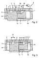
- FIG. 1 is the basic structure and operation of the invention in a hydraulic route visible.
- a pilot pressure which is performed by a piston.
- the closure member or slide present in the valve is moved so that the desired lines are connected to each other.
- Fig. 1 is essentially a connection from the pump to the hydraulic path recognizable, which is interrupted by the closing body of the valve at falling pilot pressure to make the connection hydraulic route - reservoir.
- the slide in the valve housing covers a certain area, so that in this connection to two ports can not be produced, but always a housing connection is closed.
- this overlap area is technically conditioned to exclude a connection of the hydraulic route to the reservoir.
- the valve 8 consisting essentially of a housing 1 and a slide 2, which is held by a compression spring 11 in a certain position, inter alia.
- the housing 1, whose wall thickness is reduced step-like to form a paragraph pressure spring side, has 6 holes or connection options for corresponding lines. In this case, a connection for the introduction of hydraulic oil for acting on the pressing surface 14 of the slider 2 with a certain pressure, the pilot pressure is used.
- the further holes are provided for connections to a pump 4, 4a and 4b, to a reservoir 5 and to the hydraulic path 6.
- the slider 2 is provided at a distance from the pressing surface 14 with a circumferential groove 7, the width of which results from the distance between two adjacent ports plus their diameter. This ensures that the groove 7 in the axial movement of the slider 2 in each case two of the adjacent terminals 6, 4, 5, the distance between the groove 7 of the pressing surface 14 depends on the stop of the slider 2 on the housing 1, resulting from the Impact of the return surface 12 of the slider 2 on the stop surface 9 of the housing 1 results.
- the connections 4a and 4b are provided in the housing 1 of the valve 8.
- the slider 2 has a radial incision 10, which tapers the diameter of the slide 2 to a specific diameter. This is maintained in the axial direction over a certain length until the original diameter of the slider 2 is reached again via the adjoining step.
- Another in continuation of the slide 2 subsequent stage whose diameter is greater than its original diameter, is used with the housing 1 to form a stop.
- the slider 2 is provided in the radial direction with a centrally disposed through hole 13 which penetrates the incision 10 at two points of the circumference and this affects it with its outer wall.
- the diameter of this bore 13 is equal to that of the terminals 4a and 4b.
- the slide 2 is further provided with an axially central blind hole 17 which, starting from the tikfeder devisem end, with the through hole 13 coincides.
- a bolt 18 is arranged, which is used to center the Slider 2 on the inner wall of the housing 1 is supported.
- the two holes 13 and 17 are filled with hydraulic fluid.
- the innermost step of the recess 10 serves to receive a sliding ring 16, which is within the limit of the stage, d. H. from the outer wall of the through hole 13 to the subsequent step, is axially movable.
- This sliding ring 16 has an outer diameter which is adapted to the inner diameter of the housing 1 at this point. Its width is defined by the distance of the terminals 4a and 4b from each other plus the diameter of one of these ports, both diameters, due to their function, are the same size.
- the surface of the sliding ring 16 is roughened on the outer circumference, so that although it is axially movable on the slider 2, but always a certain static friction is ensured to the inner wall of the housing 1.
- the arrangement and design of the incision 10 is of particular importance. Is the circumferential groove 7 in the region of the housing 1, where only the terminal 4 remains open, the bore 4a must be congruent with the through hole 13.
- the incision 10 adjoining the through-hole in this illustration has, as already mentioned, two stages, wherein the width of the innermost stage is so great that it forms the two connections 4a and 4b and their space covered. The subsequent step must be so wide that it extends beyond the shoulder of the housing 1, so that in conjunction with the outermost stage in this position of the slide 2, a second pressure chamber 20 is provided.
- the two bores 13 and 17 together form the third pressure chamber 21.
- the slide 2 is in the vicinity of the left inner wall of the housing 1 of the valve 8.
- a suitably dimensioned centrally mounted on the inner wall spacer ensures that the slider 2 is always kept at a distance from the inner wall of the housing 1, so that with a appropriate pilot pressure hydraulic fluid may be introduced into the first pressure chamber 19.
- the pump 4 is connected to the hydraulic path 6.
- This axial movement reaches the circumferential groove 7 in the region of the terminals 6 and 4.
- the sliding ring 16 fitting to its left boundary, is moved along.
- the return surface 12 of the slider 2 lifts off from the stop surface 9 of the housing 1 and hydraulic fluid can through the port 4 b in the free space of the incision 10 and in the, directed by the two oppositely directed stages of slide 2 and housing 1, second pressure chamber 20 flow.
- the movement in this direction continues until the switching operation is completed, i. H. until the groove 7 of the slider 2 releases the ports 4 and 5.
Landscapes
- Engineering & Computer Science (AREA)
- Physics & Mathematics (AREA)
- Fluid Mechanics (AREA)
- Mechanical Engineering (AREA)
- General Engineering & Computer Science (AREA)
- Multiple-Way Valves (AREA)
- Reciprocating Pumps (AREA)
- Stereo-Broadcasting Methods (AREA)
- Fluid-Pressure Circuits (AREA)
- Fluid-Driven Valves (AREA)
Abstract
Description
Die Erfindung betrifft ein Verfahren und eine Vorrichtung zur schnellen Umschaltung eines flüssigen oder gasförmigen Mediums in einer hydraulischen oder pneumatischen Strecke mittels einer Pumpe abhängig vom Vorsteuerdruck entweder in einen Vorratsbehälter oder in die hydraulische/pneumatische Strecke mit Hilfe eines Umschaltventils.
Die Steuerung beispielsweise eines Ölstromes in einer hydraulischen Strecke erfolgt in erster Linie über mindestens eine Pumpe, wobei die Richtung und die Durchflussmenge von in der hydraulischen Strecke angeordneten, entsprechend vorgesteuerten Ventilen festgelegt werden. Ein Ausgleich von Hydraulikmenge wird über einen Vorratsbehälter realisiert, so dass entsprechende Ventile oder Ventilanordnungen dafür vorgesehen sind, eine Flutumschaltung von der Pumpe entweder in die hydraulische Strecke oder in den Vorratsbehälter zu realisieren, wie z.B. aus der
The control of, for example, an oil flow in a hydraulic path takes place primarily via at least one pump, the direction and the flow rate of which are arranged in the hydraulic path, correspondingly pilot operated valves. A balance of hydraulic amount is realized via a reservoir, so that corresponding valves or valve assemblies are provided to realize a flood switch from the pump either in the hydraulic route or in the reservoir, such as from
So ist es beispielsweise üblich, ein Rückschlagventil mit einer parallelen Drosselstrecke einzusetzen, wobei ein entsprechend konstruktiv ausgebildeter Drosseleinsatz in dieser Drosselstrecke als Mengenregler arbeitet. Weiterhin können mehrere Ventile unterschiedlicher Funktion, beispielsweise einer Rückschlag- und einer Überdruckventilfunktion, miteinander gekoppelt werden wie ein vorgesteuertes Druckregelventil mit einem Rückschlagventil. Hierbei steht der Federraum des Druckregelkolbens über eine weitere Drosselbohrung im Druckregelkolben selbst mit einem Druck- oder Pumpenanschluss in Verbindung. Steigt der anstehende statische Druck über den Einstellwert des Druckventils, wird dieses geöffnet und lässt dabei Hydraulikflüssigkeit zum Vorratsbehälter abfließen. Dieses Abfließen erzeugt einen Druckabfall im Federraum des Druckregelkolbens, wodurch die Schließkraft der Feder aufgehoben wird und der Druckregelkolben des Rückschlagventils öffnet den Weg zum Vorratsbehälter.Thus, for example, it is customary to use a check valve with a parallel throttle section, wherein a correspondingly constructive throttle insert operates in this throttle section as a flow regulator. Furthermore, a plurality of valves of different function, such as a non-return and a relief valve function, are coupled together as a pilot-operated pressure control valve with a check valve. Here, the spring chamber of the pressure regulating piston is connected via a further throttle bore in the pressure regulating piston itself with a pressure or pump connection. If the static pressure rises above the set value of the pressure valve, it is opened, allowing hydraulic fluid to drain to the reservoir. This drain creates a pressure drop in the spring chamber of the pressure regulating piston, whereby the closing force of the spring is released and the pressure regulating piston of the check valve opens the way to the reservoir.
Für diese Lösung sind jedoch mehrere einzelne Ventile nötig, was einerseits technisch aufwendig ist und andererseits einen entsprechenden Platzbedarf erfordert.For this solution, however, several individual valves are needed, which on the one hand is technically complex and on the other hand requires a corresponding space requirement.
Eine elegantere Lösung der Flutumschaltung bzw. der Steuerung der Druckmittelwege wird in der
Dieser Vorgang der Flutumschaltung benötigt allerdings eine gewisse Zeit. So überdeckt der Ventilschieber während des Umschaltens für eine bestimmte Zeit einen definierten Bereich im Gehäuse, der technisch bedingt sein muss, damit die hydraulische Strecke nicht direkt mit dem Vorratsbehälter verbunden werden kann. In der Phase, wo der Ventilschieber die gehäuseseitigen Anschlüsse zur hydraulischen Strecke und zur Pumpe überdeckt, wird der sich sonst vor der Pumpe aufbauende Druck vom Druckbegrenzungsventil, das sich zwischen der hydraulischen Strecke und der Pumpe befindet, begrenzt.However, this process of flood switch requires a certain amount of time. Thus, the valve spool covers during the switching for a certain time a defined area in the housing, which must be technical, so that the hydraulic route can not be connected directly to the reservoir. In the phase where the valve spool covers the housing-side connections to the hydraulic line and to the pump, the pressure that builds up before the pump is limited by the pressure relief valve, which is located between the hydraulic section and the pump.
Anstelle eines Druckbegrenzungsventils ist auch der Einsatz eines Rückschlagventils bekannt. Beim Einsatz eines Rückschlagventils ist allerdings nicht gewährleistet, dass es zuverlässig funktioniert. Steigt der Vorsteuerdruck, öffnet es sich. Fällt der Vorsteuerdruck ab, spricht es zeitverzögert an und Öl kann inzwischen sowohl in die hydraulische Strecke als auch in den Vorratsbehälter abfließen.Instead of a pressure relief valve and the use of a check valve is known. However, using a check valve does not guarantee that it will work reliably. If the pilot pressure rises, it opens. If the pilot pressure drops, it responds with a time delay and oil can now flow into both the hydraulic line and in the reservoir.
Aufgabe der Erfindung ist es, das Fluid von einer Pumpe vorsteuerdruckabhängig in unterschiedliche Leitungsanschlüsse so umzuschalten, dass die dafür benötigte Zeit verkürzt und die Umschaltung mittels nur eines Ventils realisiert wird und dabei die Baugröße des Ventils nur eine unwesentliche Veränderung erfährt.The object of the invention is to switch the fluid from a pump pilot pressure dependent in different line connections so that the time required for this purpose shortened and the switching is realized by means of only one valve while the size of the valve undergoes only an insignificant change.
Erfindungsgemäß wird diese Aufgabe zunächst dadurch gelöst dass der Schieber ein erstes Schieberelement und ein zweites Schieberelement aufweist, die zumindest während eines Zeitintervalls des Umschaltvorganges unabhängig voneinander beschleunigt werden. Diese Beschleunigung dient dazu, den Umschaltvorgang zu verkürzen, um die während des Umschaltens vor der Pumpe auftretende Druckerhöhung so schnell wie möglich abzubauen, was u. a. zur Verlängerung der Lebensdauer der Pumpe führt.According to the invention, this object is initially achieved in that the slide has a first slide element and a second slide element, which are accelerated independently of each other at least during a time interval of the switching process. This acceleration serves to shorten the switching process in order to reduce the pressure increase occurring during the switching before the pump as quickly as possible, which u. a. extends the life of the pump.
Von Vorteil ist dabei die Fluidumschaltung von einer Pumpe entweder in eine fluidische Strecke oder in einen Vorratsbehälter mittels eines vorsteuerdruckabhängigen Drei-Wege-Ventils stattfinden zu lassen ohne ein zusätzliches Rückschlagventil einsetzen zu müssenThe advantage here is to allow the fluid switching of a pump either in a fluidic path or in a reservoir by means of a pilot-pressure-dependent three-way valve to take place without having to use an additional check valve
In vorteilhafter Weise wird der axialen Bewegung des Schiebers im Ventil eine weitere axiale Bewegung überlagert, woraus sich eine resultierende Bewegung ergibt, die das Ergebnis der Addition gleich- und entgegengerichteter Kräfte ist, wobei diese Kräfte während des Umschaltvorganges zeitgleich oder zeitversetzt auf den Schieber einwirken.Advantageously, the axial movement of the slide in the valve is superimposed on a further axial movement, resulting in a resulting movement, which is the result of the addition of equal and opposite forces, these forces acting simultaneously or with a time delay on the slide during the switching operation.
Dabei ist es besonders vorteilhaft, im Schieber eine definierte Ölmenge zu speichern, die während des Umschaltvorganges in die vorbestimmte Richtung lenkbar istIt is particularly advantageous to store in the slide a defined amount of oil which is steerable during the switching in the predetermined direction
Zur Realisierung dieser Abläufe und damit zur Lösung der erfindungsgemäßen Aufgabe ist es besonders vorteilhaft, dass eine Pumpe entweder mit einer fluidischen Strecke oder mit einem Vorratsbehälter mittels eines vorsteuerdruckabhängigen Drei-Wege-Ventils verbunden ist. das einen zweiteiligen Schieber mit einem ersten Schieberelement und einem zweiten Schieberelement enthält und dass das Gehäuse des Ventils über weitere Anschlüsse zur Pumpe verfügt, die sich an die vorhandenen Anschlüsse in axialer Richtung anschließen und sowohl von diesen als auch voneinander beabstandet sind.To realize these processes and thus to achieve the object according to the invention, it is particularly advantageous that a pump is connected either to a fluidic path or to a reservoir by means of a pilot-pressure-dependent three-way valve. which contains a two-part slide with a first slide element and a second slide element and that the housing of the valve has further connections to the pump, which connect to the existing connections in the axial direction and are spaced from both these and from each other.
In einer weiteren vorteilhaften Ausbildung der Erfindung verringert sich nach dem zweiten weiteren Pumpenanschluss in Richtung Druckfeder die Wandstärke des Gehäuses absatzartig und bleibt für den restlichen Gehäuseteil gleich. Die am Absatz entstandene radiale Ringfläche bildet zugleich die Anschlagfläche für den im Gehäuse geführten Schieber.In a further advantageous embodiment of the invention decreases after the second further pump connection in the direction of compression spring, the wall thickness of the housing like a paragraph and remains the same for the rest of the housing part. The resulting at the shoulder radial annular surface also forms the abutment surface for the slider guided in the housing.
Weiterhin ist die Aufgabe erfindungsgemäß dadurch gelöst, dass der Schieber vor seinem druckfederseitigen Ende einen Einschnitt aufweist, der in zwei entsprechend breiten Stufen in Richtung dieses Endes den Durchmesser des Schiebers wieder erreicht und mit einer weiteren äußersten Stufe sich dem Innendurchmesser des Gehäuses anpasst. Diese stufenartige Gestaltung des Einschnitts hat den Vorteil, dass auf diese Weise gleichzeitig definierte Anschläge realisiert werden können. So bietet sich durch die konstruktive Gestaltung des Gehäuses an, dass die mit der äußersten Stufe des Schiebers erzeugte radiale Ringfläche die Rückführfläche bildet und in vorteilhafter Weise mit der Anschlagfläche den Weg der Druckfeder begrenzt.Furthermore, the object is achieved in that the slide has an incision in front of its pressure spring end, which reaches the diameter of the slide again in two correspondingly wide steps in the direction of this end and with a further outermost stage adapts to the inner diameter of the housing. This step-like design of the incision has the advantage that simultaneously defined stops can be realized in this way. Thus, the structural design of the housing suggests that the radial annular surface created by the outermost step of the slide forms the return surface and advantageously limits the travel of the pressure spring with the stop surface.
In vorteilhafter Weise ist der Schieber in radialer Richtung mit einer zentrisch angeordneten Durchgangsbohrung versehen Der Durchmesser dieser Bohrung ist gleich dem Durchmesser der beiden zusätzlichen Pumpenanschlüsse zu wählen, um eine sichere Verbindung zwischen Pumpe und Schieber herstellen zu können und keine Druckverluste zu erzielen.Advantageously, the slide is provided in the radial direction with a centrally arranged through hole The diameter of this hole is equal to the diameter of the two additional pump connections to choose to establish a secure connection between the pump and slide can and to achieve no pressure losses.
Weiterhin ist von Vorteil, den Abstand der Durchgangsbohrung von der Andrückfläche so zu wählen, dass zu dem Zeitpunkt, wo sich die Nut des Schiebers im Überdeckungsbereich befindet, der Schieber über diese Durchgangsbohrung mit dem zusätzlichen linken Pumpenanschluss verbunden ist.Furthermore, it is advantageous to choose the distance of the through hole of the pressing surface so that at the time when the groove of the slider is in the overlap region, the slide is connected via this through hole with the additional left pump port.
In einer weiteren vorteilhaften Ausgestaltung der Erfindung ist im Schieber, von dessen druckfederseitigem Ende ausgehend, achsmittig eine in die Durchgangsbohrung einmündende Grundlochbohrung vorgesehen, in der ein Bolzen geführt wird.In a further advantageous embodiment of the invention, starting in the slide, starting from the druckfederseitigem end, axially provided in the through-hole blind hole, in which a bolt is guided.
Die im Schieber vorgesehenen Bohrungen, die im rechten Winkel zu einer Leitung verbunden sind, dienen zusammen mit dem stufenartigen Einschnitt zur Aufnahme eines definierten Ölvolumens, mit dem sich im Bedarfsfall durch Druckbeaufschlagung oder Druckentlastung Bewegungen von Bauteilen ausführen lassen. So wird damit der in der Grundlochbohrung vorhandene Bolzen innerhalb der Grundlochbohrung entweder in Richtung Gehäusewand oder in Richtung Bohrung bewegt. Dabei ist es vorteilhaft, dass er eine bestimmte Länge aufweist, um außerdem für den Schieber im Gehäuse zentrieren zu können.The holes provided in the slide, which are connected at right angles to a line, are used together with the step-like recess for receiving a defined volume of oil, which can be carried out in case of need by pressurization or pressure relief movements of components. Thus, the existing in the blind hole pin within the blind hole is moved either towards the housing wall or in the direction of drilling. It is advantageous that it has a certain length in order to be able to center also for the slide in the housing.
Eine weitere vorteilhafte Ausgestaltung der Erfindung sieht vor, dass funktionsbedingt die Breite der innersten Stufe des Einschnitts definiert wird durch die Entfernung zwischen äußerer Wandung des Durchmessers der Durchgangsbohrung bis zum Absatz der sich anschließenden zweiten Stufe und sich die Breite der zweiten Stufe aus der Summe der Durchmesser der beiden zusätzlichen Pumpenanschlüsse und deren Abstand voneinander ergibt.A further advantageous embodiment of the invention provides that functionally, the width of the innermost stage of the incision is defined by the distance between the outer wall of the diameter of the through hole to the shoulder of the subsequent second stage and the width of the second stage of the sum of the diameter the two additional pump connections and their distance from each other.
Weiterhin ist von Vorteil, dass sich die Breite der zweiten Stufe des Einschnitts an die der innersten anschließt und über die absatzartige Verringerung der Wandstärke des Gehäuses hinausgeht. Damit wird ein zusätzlicher Druckraum gebildet, der ebenso dazu dient, die axiale Bewegung des Schiebers zu beeinflussen.Furthermore, it is advantageous that the width of the second stage of the incision adjoins that of the innermost and goes beyond the heel-like reduction of the wall thickness of the housing. Thus, an additional pressure chamber is formed, which also serves to influence the axial movement of the slide.
Vorteilhaft ist außerdem, dass auf der innersten Stufe des Einschnitts ein Schiebering aufgebracht ist, der sich auf dieser axial bewegen kann. Damit wird die Masse des Schiebers in zwei Teilmassen aufgeteilt. Die miteinander in Wirkverbindung stehenden Massen können somit mit unterschiedlichen, großen Kräften beaufschlagt werden, deren Richtung ebenfalls unterschiedlich sein kann.It is also advantageous that a sliding ring is applied to the innermost stage of the incision, which can move axially on this. Thus, the mass of the slider is divided into two sub-masses. The mutually operatively connected masses can thus be acted upon with different, large forces whose direction may also be different.
Weiterhin ist von Vorteil, dass der Außendurchmesser des Schieberings mit dem Innendurchmesser des Gehäuses korrespondiert, d. h., dass beide aneinander anliegen. Damit wird gewährleistet, dass einerseits der jeweilige zusätzliche Pumpenanschluss verschlossen werden und andererseits sich der in der zweiten Druckkammer aufgebaute Druck nicht unkontrolliert abbauen kann.Furthermore, it is advantageous that the outer diameter of the sliding ring corresponds to the inner diameter of the housing, d. h., that both abut each other. This ensures that, on the one hand, the respective additional pump connection is closed and, on the other hand, the pressure built up in the second pressure chamber can not be reduced in an uncontrolled manner.
In vorteilhafter Weiterbildung der Erfindung ergibt sich die Breite des Schieberings aus der Differenz der Breite der innersten Stufenbreite und dem Durchmesser des Anschlusses. Damit ist sichergestellt, dass immer ein zusätzlicher Pumpenanschluss offen ist, wenn sich der Schiebering in einer seiner Endstellungen auf der innersten Stufe befindet.In an advantageous development of the invention, the width of the sliding ring results from the difference between the width of the innermost step width and the diameter of the connection. This ensures that an additional pump connection is always open when the sliding ring is in one of its end positions at the innermost stage.
Ein weiterer Vorteil besteht darin, dass die Oberflächenrauhigkeit von Außen- und Innendurchmesser des Schieberings unterschiedlich ist. Von besonderem Vorteil ist, wenn die Rauhigkeit der Oberfläche am Außendurchmesser des Schieberings höher ist als am Innendurchmessers. Dadurch wird eine Haftreibung zwischen der Oberfläche des Schieberings und der Fläche des Innendurchmessers des Gehäuses erreicht, die ausgenutzt wird, um eine Verzögerung bei Umkehr der Bewegungsrichtung des Schiebers zu erreichen.Another advantage is that the surface roughness of the outer and inner diameter of the sliding ring is different. It is particularly advantageous if the roughness of the surface at the outer diameter of the sliding ring is higher than at the inner diameter. As a result, a static friction between the surface of the sliding ring and the surface of the inner diameter of the housing is achieved, which is exploited to achieve a delay in reversing the direction of movement of the slider.
Außerdem ist es vorteilhaft, wenn der Schieber und Schiebering aus metallischem Werkstoff hergestellt ist. Allerdings können beide ebenso gut aus nichtmetallischem Werkstoff sowie aus Plastwerkstoff bestehen. Ebenso können die beiden Bauteile unterschiedliche Materialien aufweisen. Das ist vom jeweiligen Anwendungsfall abhängig.Moreover, it is advantageous if the slider and sliding ring is made of metallic material. However, both can equally well consist of non-metallic material and plastic material. Likewise, the two components may have different materials. This depends on the particular application.
Die Vorrichtung soll anhand eines Ausführungsbeispiels näher erläutert werden, wobei sich die Ausführungen auf eine hydraulische Strecke beziehen.The device will be explained in more detail using an exemplary embodiment, wherein the embodiments relate to a hydraulic path.
Es zeigen:
- Fig. 1:
- eine prinzipielle Darstellung der erfindungsgemäßen Lösung in einer hydraulischen Strecke
- Fig. 2 - 5:
- die Wirkungsweise des erfindungsgemäßen Umschaltventils bei unterschiedlichen Vorsteuerdrücken.
- Fig. 1:
- a schematic representation of the solution according to the invention in a hydraulic route
- Fig. 2 - 5:
- the operation of the changeover valve according to the invention at different pilot pressures.
Aus der
Gemäß
Aus den
Das Ventil 8, bestehend im Wesentlichen aus einem Gehäuse 1 und einem Schieber 2, der u. a. von einer Druckfeder 11 in einer bestimmten Stellung gehalten wird. Das Gehäuse 1, dessen Wandstärke zur Bildung eines Absatzes druckfederseitig stufenartig reduziert ist, verfügt über 6 Bohrungen bzw. Anschlussmöglichkeiten für entsprechende Leitungen. Dabei dient ein Anschluss zur Einleitung von Hydrauliköl zur Beaufschlagung der Andrückfläche 14 des Schiebers 2 mit einem bestimmten Druck, dem Vorsteuerdruck. Die weiteren Bohrungen sind für Anschlüsse an eine Pumpe 4, 4a und 4b, an einen Vorratsbehälter 5 sowie zur hydraulischen Strecke 6 vorgesehen.The
Der Schieber 2 ist in einem Abstand von der Andrückfläche 14 mit einer umlaufenden Nut 7 versehen, deren Breite sich aus dem Abstand zweier benachbarter Anschlüsse zuzüglich deren Durchmesser ergibt. Damit gewährleistet ist, dass die Nut 7 bei axialer Bewegung des Schiebers 2 jeweils zwei der benachbarten Anschlüssen 6, 4, 5 überdeckt, ist der Abstand der Nut 7 von der Andrückfläche 14 abhängig vom Anschlag des Schiebers 2 am Gehäuse 1, der sich aus dem Auftreffen der Rückführfläche 12 des Schiebers 2 auf die Anschlagfläche 9 des Gehäuses 1 ergibt.The
Für die Realisierung weiterer Pumpenanschlüsse sind im Gehäuse 1 des Ventils 8 die Anschlüsse 4a und 4b vorgesehen. Zur Steuerung der Anschlussmöglichkeit, dass entweder der Anschluss 4a oder der Anschluss 4b zur Pumpe freigegeben wird, weist der Schieber 2 einen radialen Einschnitt 10 auf, der den Durchmesser des Schiebers 2 auf einen bestimmten Durchmesser verjüngt. Dieser wird in axialer Richtung über eine bestimmte Länge beibehalten, bis über die sich daran anschließende Stufe zunächst der ursprüngliche Durchmesser des Schiebers 2 wieder erreicht wird. Eine weitere in Fortführung des Schiebers 2 sich anschließende Stufe, deren Durchmesser größer als dessen ursprünglicher Durchmesser ist, dient mit dem Gehäuse 1 zur Bildung eines Anschlages. Außerdem ist der Schieber 2 in radialer Richtung mit einer zentrisch angeordneten Durchgangsbohrung 13 versehen, die an zwei Stellen des Umfangs den Einschnitt 10 durchdringt und diesen dabei mit ihrer Außenwand tangiert. In vorteilhafter Weise ist der Durchmesser dieser Bohrung 13 gleich dem der Anschlüsse 4a bzw. 4b. Der Schieber 2 ist weiterhin mit einer achsmittigen Grundlochbohrung 17 versehen, die ausgehend von dessen druckfederseitigem Ende, mit der Durchgangsbohrung 13 zusammentrifft. In dieser Grundlochbohrung ist ein Bolzen 18 angeordnet, der sich zur Zentrierung des Schiebers 2 an der Innenwand des Gehäuses 1 abstützt. Weiterhin sind die beiden Bohrungen 13 und 17 mit Hydraulikflüssigkeit gefüllt.For the realization of further pump connections, the
Die innerste Stufe des Einschnitts 10 dient zur Aufnahme eines Schieberings 16, der innerhalb der Begrenzung der Stufe, d. h. von der Außenwand der Durchgangsbohrung 13 bis zu der sich anschließenden Stufe, axial beweglich ist. Dieser Schiebering 16 hat einen Außendurchmesser, der dem Innendurchmesser der Gehäuses 1 an dieser Stelle angepasst ist. Seine Breite wird definiert durch den Abstand der Anschlüsse 4a und 4b voneinander zuzüglich des Durchmessers eines dieser Anschlüsse, wobei beide Durchmesser, funktionsbedingt, gleich groß sind. Des Weiteren ist die Oberfläche des Schieberings 16 am Außenumfang aufgeraut, so dass dieser zwar axial auf dem Schieber 2 bewegbar ist, jedoch immer eine bestimmte Haftreibung zur Innenwand des Gehäuses 1 gewährleistet ist.The innermost step of the
Zum Aufbringen des Schieberings 16 auf die innerste Stufe des Einschnitts 10 ist es vorteilhaft, den Schieber entweder an der Stelle zu teilen, wo die nachfolgende Stufe beginnt, oder den Durchmesser der innersten Stufe als Ansatz bis zu dessen Ende beizubehalten und mit einem Gewinde zu versehen. Das weitere stufenartige Teilstück des Schiebers 2, das ein entsprechendes Innengewinde aufweist, kann dann mit dem ersten Teilstück verschraubt werden. Es sind auch andere Verbindungsmöglichkeiten beider Teilstücke denkbar, wie z. B. Kleben, Schweißen oder dergleichen, die abhängig sind vom gewählten Material des Schiebers 2. Eine andere Lösung des Problems würde sich durch eine Teilung des Schieberings 16 in mindestens zwei Teile anbieten, die dann nach dem Aufbringen auf die innerste Stufe wieder zusammengefügt werden müssten.For applying the sliding
Für die Lösung der erfindungsgemäßen Aufgabe ist die Anordnung und Gestaltung des Einschnitts 10 von besonderer Bedeutung. Befindet sich die umlaufende Nut 7 in dem Bereich des Gehäuses 1, wo nur der Anschluss 4 geöffnet bleibt, muss die Bohrung 4a deckungsgleich mit der Durchgangsbohrung 13 sein. Der sich in dieser Darstellung an die Durchgangsbohrung anschließende Einschnitt 10 verfügt, wie bereits genannt, über zwei Stufen, wobei die Breite der innersten Stufe so groß ist, dass sie die beiden Anschlüsse 4a und 4b nebst deren Zwischenraum überdeckt. Die sich anschließende Stufe muss so breit sein, dass sie dabei über den Absatz des Gehäuses 1 hinausreicht, so dass in Verbindung mit der äußersten Stufe in dieser Stellung des Schiebers 2 ein zweiter Druckraum 20 geschaffen wird. Die beiden Bohrungen 13 und 17 bilden zusammen den dritten Druckraum 21.For the solution of the object according to the invention, the arrangement and design of the
Gemäß
Gleichzeitig hebt sich die Rückführfläche 12 des Schiebers 2 von der Anschlagfläche 9 des Gehäuses 1 ab und Hydraulikflüssigkeit kann über den Anschluss 4b in den freien Raum des Einschnitts 10 sowie in den, durch die beiden entgegen gesetzt gerichteten Stufen von Schieber 2 und Gehäuse 1 gebildeten, zweiten Druckraum 20 fließen. Die Bewegung in dieser Richtung setzt sich so lange fort, bis der Umschaltvorgang abgeschlossen ist, d. h. bis die Nut 7 des Schiebers 2 die Anschlüsse 4 und 5 freigibt.At the same time, the
In der
Ist der Umschaltvorgang abgeschlossen, wie aus
Fällt der Vorsteuerdruck, was aus der
Claims (25)
- Method for releasing an outlet connection with the aid of a valve (8) which has a housing (1) with an inlet connection (3) and with a first outlet connection (6) and a second outlet connection (5), and with a slide (2) movable in the housing (1), the slide (2) having a first slide element (2) and a second slide element (16) which are accelerated independently of one another, at least during a time interval of the switching operation, furthermore the slide (2) having, before its end located on the compression-spring side, an indentation (10) which reaches the diameter of the slide (2) again in two steps of corresponding width in the direction of this end and which is adapted by means of a further outermost step to the inside diameter of the housing (1).
- Method according to Claim 1, characterized in that fluid switching by a pump either into a fluidic zone (6) or into a reservoir (5) takes place by means of a three-way valve (8) dependent on pilot control pressure.
- Method according to Claim 1, characterized in that a rise or fall in the pilot control pressure triggers an axial movement of the slide (2) in the valve (8), upon which a further axial movement is superposed.
- Method according to Claims 1 to 3, characterized in that the resulting movement of the slide (2) arises from the addition of codirectional and contradirectional forces.
- Method according to Claims 1 to 4, characterized in that the superposition of the movement of the slide (2) takes place simultaneously or with a time offset during the switching operation.
- Method according to Claims 1 to 5, characterized in that an oil quantity stored in the slide (2) is deflectable into the predetermined direction during the switching operation.
- Device for carrying out the method according to Claims 1 to 6, characterized in that a pump is connected either to a fluidic zone (6) or to a reservoir (5) by means of a three-way valve (8) dependent on pilot control pressure, which contains a two-part slide (2) with a first slide element (2) and with a second slide element (16).
- Device for carrying out the method according to Claims 1 to 7, characterized in that the housing (1) of the valve (8) has further connections to the pump (4a and 4b), which are adjacent in the axial direction to the existing connections (6, 4, 5) and are spaced apart both from these and from one another.
- Device according to Claim 8, characterized in that, after the connection (4b) on the compression-spring side, the wall thickness of the housing (1) decreases in the manner of a shoulder and remains the same for the remaining housing part, and the radial annular surface which has occurred at the shoulder forms the abutment surface (9).
- Device according to Claim 9, characterized in that the radial annular surface formed by means of the outermost step forms the return surface (12) which with the abutment surface (9) limits the excursion of the compression spring (11).
- Device according to Claims 1 to 10, characterized in that the slide (2) is provided in the radial direction with a centrically arranged through-bore (13), the diameter of which is identical to the diameter of the connections (4a) and (4b).
- Device according to Claim 11, characterized in that the distance of the through-bore (13) from the press-on surface (14) is selected such that, while the groove (7) of the slide (2) is in the overlap region (15), a connection to the connection (4a) is made by the through-bore (13).
- Device according to Claims 11 and 12, characterized in that a blind-hole bore (17) which issues into the through-bore (13) and in which a bolt (18) is guided is provided axially centrally in the slide (2), starting from that end of the latter which is on the compression-spring side.
- Device according to Claim 13, characterized in that the bolt (18) is supported on the end face against the inner wall of the housing (1) and has a length which is smaller than or equal to that of the blind-hole bore (17).
- Device according to one of Claims 1 to 9, characterized in that the width of the innermost step of the indentation (10) is defined by the distance between the outer wall of the diameter of the through-bore (13) and the shoulder of the adjoining second step.
- Device according to one of Claims 1 to 9, characterized in that the width of the second step arises from the sum of the diameters of the connections (4a) and (4b) and their distance from one another.
- Device according to one of Claims 1 to 9, characterized in that the width of the second step of the indentation (10) adjoins that of the innermost step and goes beyond the shoulder-like decrease in the wall thickness of the housing (1).
- Device according to one of the preceding claims, characterized in that a sliding ring (16) is mounted on the innermost step of the indentation (10) and can move axially on the said step.
- Device according to Claim 18, characterized in that the outside diameter of the sliding ring (16) corresponds to the inside diameter of the housing (1).
- Device according to Claims 18 and 19, characterized in that the outside diameter of the sliding ring (16) forms with the inside diameter of the housing (1) a friction pairing.
- Device according to Claims 18 to 20, characterized in that the inside diameter of the sliding ring (16) forms with the diameter of the indentation (10) a gap.
- Device according to one of Claims 18 to 21, characterized in that the width of the sliding ring (16) arises from the difference in the width of the innermost step and the diameter of the connection (4a).
- Device according to one of Claims 18 to 22, characterized in that the surface roughness of the outside and the inside diameter of the sliding ring (16) is different.
- Device according to Claim 19, characterized in that the roughness of the surface of the outside diameter of the sliding ring (16) is higher than that of the inside diameter.
- Device according to one of the preceding Claims 1 to 24, characterized in that the slide (2), sliding ring (16) and housing can be produced from metallic or non-metallic material or plastic.
Applications Claiming Priority (2)
| Application Number | Priority Date | Filing Date | Title |
|---|---|---|---|
| DE10338881 | 2003-08-23 | ||
| DE10338881 | 2003-08-23 |
Publications (3)
| Publication Number | Publication Date |
|---|---|
| EP1510699A2 EP1510699A2 (en) | 2005-03-02 |
| EP1510699A3 EP1510699A3 (en) | 2005-07-20 |
| EP1510699B1 true EP1510699B1 (en) | 2008-03-05 |
Family
ID=34089182
Family Applications (1)
| Application Number | Title | Priority Date | Filing Date |
|---|---|---|---|
| EP20040018691 Expired - Lifetime EP1510699B1 (en) | 2003-08-23 | 2004-08-06 | Method and device for switching a fluid flow |
Country Status (5)
| Country | Link |
|---|---|
| US (1) | US7458396B2 (en) |
| EP (1) | EP1510699B1 (en) |
| JP (1) | JP2005069482A (en) |
| AT (1) | ATE388331T1 (en) |
| DE (2) | DE502004006385D1 (en) |
Families Citing this family (2)
| Publication number | Priority date | Publication date | Assignee | Title |
|---|---|---|---|---|
| CN110124384B (en) * | 2019-05-19 | 2022-03-15 | 非润科技(山东)有限公司 | Sewage treatment system |
| US11300222B1 (en) | 2020-11-18 | 2022-04-12 | Striped Monkey IP | Hydraulic valve spool assembly with metering land sections |
Family Cites Families (12)
| Publication number | Priority date | Publication date | Assignee | Title |
|---|---|---|---|---|
| US3107693A (en) * | 1961-05-24 | 1963-10-22 | Robertshaw Controls Co | Pneumatic relay |
| US3267965A (en) * | 1963-03-28 | 1966-08-23 | Airmatic Valve Inc | Pilot operated spool valve |
| US3548879A (en) * | 1968-11-12 | 1970-12-22 | Teldix Gmbh | Three-way valve |
| US3610285A (en) * | 1969-12-11 | 1971-10-05 | Scovill Manufacturing Co | Sliding valve |
| JPS5326686B2 (en) * | 1973-11-07 | 1978-08-03 | ||
| US4187884A (en) * | 1978-06-12 | 1980-02-12 | General Gas Light Company | Four-way valve employing fluid spring |
| JPS5655762A (en) * | 1979-10-15 | 1981-05-16 | Hitachi Ltd | Fluid control valve |
| DE3629479A1 (en) * | 1985-09-03 | 1987-07-16 | Barmag Barmer Maschf | Directional control valve |
| US4763691A (en) * | 1985-09-03 | 1988-08-16 | Barmag Barmer Maschinenfabrik Aktiengesellschaft | Hydraulic control valve |
| US4649957A (en) * | 1986-01-27 | 1987-03-17 | The Aro Corporation | Fluid assisted spring return for pilot operated, spool valve |
| DE3723672A1 (en) * | 1987-07-17 | 1989-01-26 | Wessel Hydraulik | Non-return valve with an integrated pressure-regulating piston |
| DE10135298A1 (en) * | 2001-07-24 | 2003-02-13 | Bosch Rexroth Ag | valve assembly |
-
2004
- 2004-08-06 EP EP20040018691 patent/EP1510699B1/en not_active Expired - Lifetime
- 2004-08-06 AT AT04018691T patent/ATE388331T1/en not_active IP Right Cessation
- 2004-08-06 DE DE200450006385 patent/DE502004006385D1/en not_active Expired - Lifetime
- 2004-08-06 DE DE200410038193 patent/DE102004038193A1/en not_active Withdrawn
- 2004-08-17 US US10/919,941 patent/US7458396B2/en not_active Expired - Fee Related
- 2004-08-20 JP JP2004240676A patent/JP2005069482A/en not_active Withdrawn
Also Published As
| Publication number | Publication date |
|---|---|
| DE102004038193A1 (en) | 2005-03-17 |
| ATE388331T1 (en) | 2008-03-15 |
| US7458396B2 (en) | 2008-12-02 |
| DE502004006385D1 (en) | 2008-04-17 |
| JP2005069482A (en) | 2005-03-17 |
| US20050039803A1 (en) | 2005-02-24 |
| EP1510699A2 (en) | 2005-03-02 |
| EP1510699A3 (en) | 2005-07-20 |
Similar Documents
| Publication | Publication Date | Title |
|---|---|---|
| DE3913460C2 (en) | Hydraulic reversing valve | |
| DE102008059436B3 (en) | Hydraulic control valve for controlling double acting working cylinder, has annular channel formed in housing, and recess producing connection of contacts, where dimension of recess is twice larger than another recesse | |
| DE2543466A1 (en) | FLUID CONTROLLED VALVE | |
| EP0066274B1 (en) | Valve arrangement for increasing the operating speed of a working cylinder | |
| DE3323363A1 (en) | PRE-CONTROLLED PRESSURE REDUCING VALVE | |
| DE3708248A1 (en) | 2-WAY VALVE | |
| EP1851098B1 (en) | Combined spring accumulator and service brake cylinder with breather device | |
| DE69102079T2 (en) | Brake valve with pressure limiting function. | |
| DE3104957C2 (en) | Hydraulically operated press safety valve | |
| DE2624272A1 (en) | ARRANGEMENT FOR A HYDRAULICALLY OPERATED 5/3-WAY VALVE IN SPOOL DESIGN | |
| DE3341643A1 (en) | Pilot-controlled pressure relief and control valve | |
| EP1135614A1 (en) | Releasable check valve for very high system pressures | |
| DE29704758U1 (en) | Hydraulic switching unit | |
| DE2923467C2 (en) | Monitoring device | |
| EP0017036A1 (en) | Small dosing pump | |
| EP0222858B2 (en) | Pipe cut-off device | |
| EP1510699B1 (en) | Method and device for switching a fluid flow | |
| DE19725944C1 (en) | Hydraulic assist motor vehicle steering rack | |
| DE2156696A1 (en) | CONTROL DEVICE WITH A MEASURING SPINDLE AND A DRIVE PART | |
| DE3817123A1 (en) | SAFETY VALVE | |
| DE102010050323A1 (en) | Hydraulic control valve with a arranged in the hollow valve spool control piston | |
| EP1801473A2 (en) | Hydraulic valve | |
| DE102008059437B3 (en) | Hydraulic control valve for controlling operating cylinder, has control spools, where each spool is associated with linear variable differential transformer and hydraulic pilot controller coupled to system, for separate control of spools | |
| DE3836300C2 (en) | magnetic valve | |
| DE3048229C2 (en) | Check valve for pit lining stamps |
Legal Events
| Date | Code | Title | Description |
|---|---|---|---|
| PUAI | Public reference made under article 153(3) epc to a published international application that has entered the european phase |
Free format text: ORIGINAL CODE: 0009012 |
|
| AK | Designated contracting states |
Kind code of ref document: A2 Designated state(s): AT BE BG CH CY CZ DE DK EE ES FI FR GB GR HU IE IT LI LU MC NL PL PT RO SE SI SK TR |
|
| AX | Request for extension of the european patent |
Extension state: AL HR LT LV MK |
|
| PUAL | Search report despatched |
Free format text: ORIGINAL CODE: 0009013 |
|
| AK | Designated contracting states |
Kind code of ref document: A3 Designated state(s): AT BE BG CH CY CZ DE DK EE ES FI FR GB GR HU IE IT LI LU MC NL PL PT RO SE SI SK TR |
|
| AX | Request for extension of the european patent |
Extension state: AL HR LT LV MK |
|
| 17P | Request for examination filed |
Effective date: 20060120 |
|
| AKX | Designation fees paid |
Designated state(s): AT BE BG CH CY CZ DE DK EE ES FI FR GB GR HU IE IT LI LU MC NL PL PT RO SE SI SK TR |
|
| 17Q | First examination report despatched |
Effective date: 20061117 |
|
| GRAP | Despatch of communication of intention to grant a patent |
Free format text: ORIGINAL CODE: EPIDOSNIGR1 |
|
| GRAS | Grant fee paid |
Free format text: ORIGINAL CODE: EPIDOSNIGR3 |
|
| GRAA | (expected) grant |
Free format text: ORIGINAL CODE: 0009210 |
|
| AK | Designated contracting states |
Kind code of ref document: B1 Designated state(s): AT BE BG CH CY CZ DE DK EE ES FI FR GB GR HU IE IT LI LU MC NL PL PT RO SE SI SK TR |
|
| REG | Reference to a national code |
Ref country code: GB Ref legal event code: FG4D Free format text: NOT ENGLISH |
|
| REG | Reference to a national code |
Ref country code: CH Ref legal event code: EP |
|
| REG | Reference to a national code |
Ref country code: IE Ref legal event code: FG4D Free format text: LANGUAGE OF EP DOCUMENT: GERMAN |
|
| REF | Corresponds to: |
Ref document number: 502004006385 Country of ref document: DE Date of ref document: 20080417 Kind code of ref document: P |
|
| PG25 | Lapsed in a contracting state [announced via postgrant information from national office to epo] |
Ref country code: ES Free format text: LAPSE BECAUSE OF FAILURE TO SUBMIT A TRANSLATION OF THE DESCRIPTION OR TO PAY THE FEE WITHIN THE PRESCRIBED TIME-LIMIT Effective date: 20080616 Ref country code: FI Free format text: LAPSE BECAUSE OF FAILURE TO SUBMIT A TRANSLATION OF THE DESCRIPTION OR TO PAY THE FEE WITHIN THE PRESCRIBED TIME-LIMIT Effective date: 20080305 |
|
| NLV1 | Nl: lapsed or annulled due to failure to fulfill the requirements of art. 29p and 29m of the patents act | ||
| PG25 | Lapsed in a contracting state [announced via postgrant information from national office to epo] |
Ref country code: PL Free format text: LAPSE BECAUSE OF FAILURE TO SUBMIT A TRANSLATION OF THE DESCRIPTION OR TO PAY THE FEE WITHIN THE PRESCRIBED TIME-LIMIT Effective date: 20080305 Ref country code: SI Free format text: LAPSE BECAUSE OF FAILURE TO SUBMIT A TRANSLATION OF THE DESCRIPTION OR TO PAY THE FEE WITHIN THE PRESCRIBED TIME-LIMIT Effective date: 20080305 |
|
| REG | Reference to a national code |
Ref country code: IE Ref legal event code: FD4D |
|
| PG25 | Lapsed in a contracting state [announced via postgrant information from national office to epo] |
Ref country code: SK Free format text: LAPSE BECAUSE OF FAILURE TO SUBMIT A TRANSLATION OF THE DESCRIPTION OR TO PAY THE FEE WITHIN THE PRESCRIBED TIME-LIMIT Effective date: 20080305 Ref country code: CZ Free format text: LAPSE BECAUSE OF FAILURE TO SUBMIT A TRANSLATION OF THE DESCRIPTION OR TO PAY THE FEE WITHIN THE PRESCRIBED TIME-LIMIT Effective date: 20080305 Ref country code: SE Free format text: LAPSE BECAUSE OF FAILURE TO SUBMIT A TRANSLATION OF THE DESCRIPTION OR TO PAY THE FEE WITHIN THE PRESCRIBED TIME-LIMIT Effective date: 20080605 Ref country code: PT Free format text: LAPSE BECAUSE OF FAILURE TO SUBMIT A TRANSLATION OF THE DESCRIPTION OR TO PAY THE FEE WITHIN THE PRESCRIBED TIME-LIMIT Effective date: 20080805 Ref country code: NL Free format text: LAPSE BECAUSE OF FAILURE TO SUBMIT A TRANSLATION OF THE DESCRIPTION OR TO PAY THE FEE WITHIN THE PRESCRIBED TIME-LIMIT Effective date: 20080305 |
|
| PG25 | Lapsed in a contracting state [announced via postgrant information from national office to epo] |
Ref country code: RO Free format text: LAPSE BECAUSE OF FAILURE TO SUBMIT A TRANSLATION OF THE DESCRIPTION OR TO PAY THE FEE WITHIN THE PRESCRIBED TIME-LIMIT Effective date: 20080305 |
|
| EN | Fr: translation not filed | ||
| PLBE | No opposition filed within time limit |
Free format text: ORIGINAL CODE: 0009261 |
|
| STAA | Information on the status of an ep patent application or granted ep patent |
Free format text: STATUS: NO OPPOSITION FILED WITHIN TIME LIMIT |
|
| PG25 | Lapsed in a contracting state [announced via postgrant information from national office to epo] |
Ref country code: IE Free format text: LAPSE BECAUSE OF FAILURE TO SUBMIT A TRANSLATION OF THE DESCRIPTION OR TO PAY THE FEE WITHIN THE PRESCRIBED TIME-LIMIT Effective date: 20080305 Ref country code: DK Free format text: LAPSE BECAUSE OF FAILURE TO SUBMIT A TRANSLATION OF THE DESCRIPTION OR TO PAY THE FEE WITHIN THE PRESCRIBED TIME-LIMIT Effective date: 20080305 |
|
| 26N | No opposition filed |
Effective date: 20081208 |
|
| PG25 | Lapsed in a contracting state [announced via postgrant information from national office to epo] |
Ref country code: MC Free format text: LAPSE BECAUSE OF NON-PAYMENT OF DUE FEES Effective date: 20080831 |
|
| REG | Reference to a national code |
Ref country code: CH Ref legal event code: PL |
|
| GBPC | Gb: european patent ceased through non-payment of renewal fee |
Effective date: 20080806 |
|
| PG25 | Lapsed in a contracting state [announced via postgrant information from national office to epo] |
Ref country code: EE Free format text: LAPSE BECAUSE OF FAILURE TO SUBMIT A TRANSLATION OF THE DESCRIPTION OR TO PAY THE FEE WITHIN THE PRESCRIBED TIME-LIMIT Effective date: 20080305 Ref country code: BG Free format text: LAPSE BECAUSE OF FAILURE TO SUBMIT A TRANSLATION OF THE DESCRIPTION OR TO PAY THE FEE WITHIN THE PRESCRIBED TIME-LIMIT Effective date: 20080605 Ref country code: FR Free format text: LAPSE BECAUSE OF FAILURE TO SUBMIT A TRANSLATION OF THE DESCRIPTION OR TO PAY THE FEE WITHIN THE PRESCRIBED TIME-LIMIT Effective date: 20081226 |
|
| PG25 | Lapsed in a contracting state [announced via postgrant information from national office to epo] |
Ref country code: LI Free format text: LAPSE BECAUSE OF NON-PAYMENT OF DUE FEES Effective date: 20080831 Ref country code: CH Free format text: LAPSE BECAUSE OF NON-PAYMENT OF DUE FEES Effective date: 20080831 |
|
| PG25 | Lapsed in a contracting state [announced via postgrant information from national office to epo] |
Ref country code: BE Free format text: LAPSE BECAUSE OF NON-PAYMENT OF DUE FEES Effective date: 20080831 |
|
| PG25 | Lapsed in a contracting state [announced via postgrant information from national office to epo] |
Ref country code: IT Free format text: LAPSE BECAUSE OF FAILURE TO SUBMIT A TRANSLATION OF THE DESCRIPTION OR TO PAY THE FEE WITHIN THE PRESCRIBED TIME-LIMIT Effective date: 20080305 |
|
| PG25 | Lapsed in a contracting state [announced via postgrant information from national office to epo] |
Ref country code: CY Free format text: LAPSE BECAUSE OF FAILURE TO SUBMIT A TRANSLATION OF THE DESCRIPTION OR TO PAY THE FEE WITHIN THE PRESCRIBED TIME-LIMIT Effective date: 20080305 |
|
| PG25 | Lapsed in a contracting state [announced via postgrant information from national office to epo] |
Ref country code: AT Free format text: LAPSE BECAUSE OF NON-PAYMENT OF DUE FEES Effective date: 20080806 |
|
| PG25 | Lapsed in a contracting state [announced via postgrant information from national office to epo] |
Ref country code: GB Free format text: LAPSE BECAUSE OF NON-PAYMENT OF DUE FEES Effective date: 20080806 |
|
| PG25 | Lapsed in a contracting state [announced via postgrant information from national office to epo] |
Ref country code: LU Free format text: LAPSE BECAUSE OF NON-PAYMENT OF DUE FEES Effective date: 20080806 Ref country code: HU Free format text: LAPSE BECAUSE OF FAILURE TO SUBMIT A TRANSLATION OF THE DESCRIPTION OR TO PAY THE FEE WITHIN THE PRESCRIBED TIME-LIMIT Effective date: 20080906 |
|
| PG25 | Lapsed in a contracting state [announced via postgrant information from national office to epo] |
Ref country code: TR Free format text: LAPSE BECAUSE OF FAILURE TO SUBMIT A TRANSLATION OF THE DESCRIPTION OR TO PAY THE FEE WITHIN THE PRESCRIBED TIME-LIMIT Effective date: 20080305 |
|
| PG25 | Lapsed in a contracting state [announced via postgrant information from national office to epo] |
Ref country code: GR Free format text: LAPSE BECAUSE OF FAILURE TO SUBMIT A TRANSLATION OF THE DESCRIPTION OR TO PAY THE FEE WITHIN THE PRESCRIBED TIME-LIMIT Effective date: 20080606 |
|
| REG | Reference to a national code |
Ref country code: DE Ref legal event code: R081 Ref document number: 502004006385 Country of ref document: DE Owner name: SCHAEFFLER TECHNOLOGIES AG & CO. KG, DE Free format text: FORMER OWNER: SCHAEFFLER TECHNOLOGIES GMBH & CO. KG, 91074 HERZOGENAURACH, DE Effective date: 20120828 Ref country code: DE Ref legal event code: R081 Ref document number: 502004006385 Country of ref document: DE Owner name: SCHAEFFLER TECHNOLOGIES GMBH & CO. KG, DE Free format text: FORMER OWNER: SCHAEFFLER TECHNOLOGIES GMBH & CO. KG, 91074 HERZOGENAURACH, DE Effective date: 20120828 |
|
| REG | Reference to a national code |
Ref country code: DE Ref legal event code: R081 Ref document number: 502004006385 Country of ref document: DE Owner name: SCHAEFFLER TECHNOLOGIES AG & CO. KG, DE Free format text: FORMER OWNER: SCHAEFFLER TECHNOLOGIES AG & CO. KG, 91074 HERZOGENAURACH, DE Effective date: 20140218 Ref country code: DE Ref legal event code: R081 Ref document number: 502004006385 Country of ref document: DE Owner name: SCHAEFFLER TECHNOLOGIES GMBH & CO. KG, DE Free format text: FORMER OWNER: SCHAEFFLER TECHNOLOGIES AG & CO. KG, 91074 HERZOGENAURACH, DE Effective date: 20140218 |
|
| REG | Reference to a national code |
Ref country code: DE Ref legal event code: R081 Ref document number: 502004006385 Country of ref document: DE Owner name: SCHAEFFLER TECHNOLOGIES AG & CO. KG, DE Free format text: FORMER OWNER: SCHAEFFLER TECHNOLOGIES GMBH & CO. KG, 91074 HERZOGENAURACH, DE Effective date: 20150211 |
|
| PGFP | Annual fee paid to national office [announced via postgrant information from national office to epo] |
Ref country code: DE Payment date: 20151029 Year of fee payment: 12 |
|
| REG | Reference to a national code |
Ref country code: DE Ref legal event code: R119 Ref document number: 502004006385 Country of ref document: DE |
|
| PG25 | Lapsed in a contracting state [announced via postgrant information from national office to epo] |
Ref country code: DE Free format text: LAPSE BECAUSE OF NON-PAYMENT OF DUE FEES Effective date: 20170301 |
|
| P01 | Opt-out of the competence of the unified patent court (upc) registered |
Effective date: 20230522 |