EP0200182A2 - Piston-type hydraulic control valve - Google Patents
Piston-type hydraulic control valve Download PDFInfo
- Publication number
- EP0200182A2 EP0200182A2 EP86105787A EP86105787A EP0200182A2 EP 0200182 A2 EP0200182 A2 EP 0200182A2 EP 86105787 A EP86105787 A EP 86105787A EP 86105787 A EP86105787 A EP 86105787A EP 0200182 A2 EP0200182 A2 EP 0200182A2
- Authority
- EP
- European Patent Office
- Prior art keywords
- control
- piston
- edges
- course
- housing
- Prior art date
- Legal status (The legal status is an assumption and is not a legal conclusion. Google has not performed a legal analysis and makes no representation as to the accuracy of the status listed.)
- Granted
Links
- 238000011161 development Methods 0.000 claims abstract description 4
- 238000010276 construction Methods 0.000 claims description 4
- 238000006073 displacement reaction Methods 0.000 claims description 4
- 239000007788 liquid Substances 0.000 claims description 4
- 238000004519 manufacturing process Methods 0.000 abstract description 3
- 230000008878 coupling Effects 0.000 abstract description 2
- 238000010168 coupling process Methods 0.000 abstract description 2
- 238000005859 coupling reaction Methods 0.000 abstract description 2
- 239000012530 fluid Substances 0.000 abstract 1
- 230000008901 benefit Effects 0.000 description 3
- 230000008859 change Effects 0.000 description 3
- 238000000034 method Methods 0.000 description 3
- 230000008569 process Effects 0.000 description 3
- 230000018109 developmental process Effects 0.000 description 2
- 238000003801 milling Methods 0.000 description 2
- 230000000750 progressive effect Effects 0.000 description 2
- 230000000694 effects Effects 0.000 description 1
- 238000007373 indentation Methods 0.000 description 1
- 230000003993 interaction Effects 0.000 description 1
- 239000002655 kraft paper Substances 0.000 description 1
- 230000002093 peripheral effect Effects 0.000 description 1
- 230000007704 transition Effects 0.000 description 1
Images
Classifications
-
- F—MECHANICAL ENGINEERING; LIGHTING; HEATING; WEAPONS; BLASTING
- F16—ENGINEERING ELEMENTS AND UNITS; GENERAL MEASURES FOR PRODUCING AND MAINTAINING EFFECTIVE FUNCTIONING OF MACHINES OR INSTALLATIONS; THERMAL INSULATION IN GENERAL
- F16K—VALVES; TAPS; COCKS; ACTUATING-FLOATS; DEVICES FOR VENTING OR AERATING
- F16K11/00—Multiple-way valves, e.g. mixing valves; Pipe fittings incorporating such valves
- F16K11/02—Multiple-way valves, e.g. mixing valves; Pipe fittings incorporating such valves with all movable sealing faces moving as one unit
- F16K11/06—Multiple-way valves, e.g. mixing valves; Pipe fittings incorporating such valves with all movable sealing faces moving as one unit comprising only sliding valves, i.e. sliding closure elements
- F16K11/065—Multiple-way valves, e.g. mixing valves; Pipe fittings incorporating such valves with all movable sealing faces moving as one unit comprising only sliding valves, i.e. sliding closure elements with linearly sliding closure members
- F16K11/07—Multiple-way valves, e.g. mixing valves; Pipe fittings incorporating such valves with all movable sealing faces moving as one unit comprising only sliding valves, i.e. sliding closure elements with linearly sliding closure members with cylindrical slides
-
- Y—GENERAL TAGGING OF NEW TECHNOLOGICAL DEVELOPMENTS; GENERAL TAGGING OF CROSS-SECTIONAL TECHNOLOGIES SPANNING OVER SEVERAL SECTIONS OF THE IPC; TECHNICAL SUBJECTS COVERED BY FORMER USPC CROSS-REFERENCE ART COLLECTIONS [XRACs] AND DIGESTS
- Y10—TECHNICAL SUBJECTS COVERED BY FORMER USPC
- Y10T—TECHNICAL SUBJECTS COVERED BY FORMER US CLASSIFICATION
- Y10T137/00—Fluid handling
- Y10T137/8593—Systems
- Y10T137/86493—Multi-way valve unit
- Y10T137/86574—Supply and exhaust
- Y10T137/8667—Reciprocating valve
- Y10T137/86694—Piston valve
- Y10T137/8671—With annular passage [e.g., spool]
-
- Y—GENERAL TAGGING OF NEW TECHNOLOGICAL DEVELOPMENTS; GENERAL TAGGING OF CROSS-SECTIONAL TECHNOLOGIES SPANNING OVER SEVERAL SECTIONS OF THE IPC; TECHNICAL SUBJECTS COVERED BY FORMER USPC CROSS-REFERENCE ART COLLECTIONS [XRACs] AND DIGESTS
- Y10—TECHNICAL SUBJECTS COVERED BY FORMER USPC
- Y10T—TECHNICAL SUBJECTS COVERED BY FORMER US CLASSIFICATION
- Y10T137/00—Fluid handling
- Y10T137/8593—Systems
- Y10T137/86493—Multi-way valve unit
- Y10T137/86718—Dividing into parallel flow paths with recombining
- Y10T137/86734—With metering feature
Definitions
- the invention relates to a hydraulic control valve in the piston-slide construction with a control piston arranged longitudinally displaceably in a housing, which regulates at least one liquid flow flowing through the housing by means of circumferential recesses and thereby control surfaces formed around a piston core on piston collars, in that through the recesses between the piston collars Corresponding longitudinal displacement of the control piston on the housing side between webs rotating control chambers are coupled, the collars of the control piston having progressively releasing control edges of the control chambers.
- control valves have become known from DE-PS 27 17 384 and DE-OS 32 05 860. Both control valves are so-called continuous valves, in which the valve can be precisely controlled by virtue of the fact that the control edges have triangular recesses which, based on the cross section of the control surfaces, usually have the spatial shape of a half-cone. With such piston geometries it is achieved that, during the opening stroke of the valve piston, its control edges, starting from the tip of the triangular recess, progressively release the control chambers arranged in a ring around the piston, whereby fine control of the valve with the desired accuracy is given in the area of small flow rates.
- control edges interacting in a straight line in the so-called zero cut with the control chambers, the liquid flow at the control edges is not interrupted, which is accompanied by a force overweight in the direction of flow of the medium, which in contrast to the desired fine control strives to abruptly advance the opening movement of the piston.
- control edges as triangular recesses or the control surfaces as semi-conical recesses has the disadvantage that fine control of the valve can be achieved in the triangular region of the control edges, but that when the control piston is moved out of this region when the full open position is reached, the Volume flow of the medium suddenly increased, which makes the unwanted sudden increase in flow forces occurs.
- Another disadvantage of the design of the control edges is their complex manufacture.
- the shape of the control edges or recesses in relation to the control surfaces requires a high amount of milling work, since the opening stroke characteristic of the control valve depends to a large extent on the accuracy of the design of the control edges or control surfaces. Since the piston is a hardened component, the hardening process that follows the milling of the control edge or control surface course again carries inaccuracies in this regard into the workpiece.
- the invention has for its object to improve a generic valve in such a way that abrupt movements of the flow forces are avoided with good controllability of the valve.
- the advantage is connected that the increase in the flow cross-section for the medium takes place progressively until the opening cross-section of the control chambers is completely released, without a sudden change in direction of the control edge taking place.
- the characteristic of the flow forces as a function of the opening cross section has a progressive, kink-free course, which ensures that a sudden increase in flow forces with the disadvantages described for valve control is reliably avoided.
- control edge widens from the closed position of the piston, i. H. the complete coverage of the control chambers on the housing side by the piston, curved in the manner of a semi-periodic sine curve up to the full opening cross-section.
- a further advantage of such a configuration is the simple production of the control edges or control surfaces, since these are machined out of the full piston cross-section when the recesses are machined by turning them in one working direction. H. Turning process can be made. The subsequent surface hardening of the piston with control surfaces and control edges does not involve any inaccuracies because of the smooth transitions.
- control edges of the piston are designed as rectilinear peripheral edges, while at the same time the edges of the webs between the housing-side control spaces are designed in the manner according to the invention, so that the same advantageous effects in the interaction of control edges and Webs results.
- the invention is not limited to the continuous valves described in the prior art, but can be applied to all hydraulic valves in piston-slide valve B; aaa., Because independent of a constant course of the opening characteristic for all valves in piston valve - Construction of any kind of undesirable and avoidable control strikes as a result of a sudden increase in flow forces is avoided.
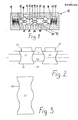
- FIG. 1 the so-called main stage 10 of a continuous directional valve with directional control in piston-slide construction is shown, which in its Movement sequence can be controlled by a pilot control, not shown.
- the main stage 10 has a housing 11 in which a piston 12 is movably arranged.
- the piston 12 is held in the rest position by two centering springs 13 supported on the housing 11, with chambers 15 for accommodating the centering springs 13 being formed in the housing 11 at the opposite ends of the piston 12.
- the chambers 15 have bores 14, which each establish a connection to the hydraulic pilot control, not shown.
- an axial guide bore 16 is formed for the control piston 12, which in this case has three circumferential recesses 17 arranged at a distance from one another, so that there are two piston collars 21 with the full piston cross section between them.
- the recesses 17 comprise an annular piston core 18, so that radially projecting control surfaces 19 result from the piston core 18, the outer edge of which, as a control edge 20, slides sealingly on the inner surface of the axial guide bore 16.
- the control edges 20 have triangular recesses 22, several of which are arranged at a distance from one another in the course of the control edge 20 surrounding the piston collar 21.
- the recesses 22 have a semi-conical shape in the direction of the piston core.
- the piston configuration 12 is surrounded by control chambers 23 which are formed in the housing 11 and surround the control piston 12 in an annular manner and which are connected to the outside via connection bores 27 to 30 of the valve and therefore not shown aggregates such as tank, pump, consumer are connected.
- the connection to the tank is denoted by 27, the connection to the pump by 28 and 29 and 30 each a connection to a consumer.
- webs 25 are arranged which cooperate with the control edges 20 of the piston 12 during its axial movement.
- two control chambers 23 are connected by a control channel 26, starting from the tank bore 27.
- FIG. 2 shows the design of the control piston according to the invention, in the form of a partial section of the control piston 12 with piston core 18, to which two piston collars 21 with two retracted control surfaces 19 are shown in sections on both sides.
- the recess 17 located between the control surfaces 19 has a connection to a housing-side control chamber 23 and to the connection bore 29.
- the control edges 20 of the piston collars 21 now run without a sudden change in direction in the manner of a sine curve tapering the width of the piston collar 21.
- control edge 20 has twice a sinusoidal vibration of half a period.
- any type of design of the course of the control edges must be regarded as belonging to the invention, which is a sudden one Avoids a change in direction of the course of the control edges with an abrupt increase in the flow forces, in particular also a straight line instead of a curved course of the control edges, as long as there is no linear section in between in the direction of the piston transverse axis.
- control surfaces 19 are arranged perpendicular to the piston core 18, so that the sine curve of the control edge 20 results in an opening cross section of the piston 12 up to its piston core 18.
- a further advantageous fine-tuning of the valve is possible in that the control surfaces are arranged obliquely towards the piston core, in such a way that a progressive release of the flow cross-section also results in the radial direction.
Landscapes
- Engineering & Computer Science (AREA)
- General Engineering & Computer Science (AREA)
- Mechanical Engineering (AREA)
- Sliding Valves (AREA)
- Valve Device For Special Equipments (AREA)
- Fluid-Driven Valves (AREA)
- Braking Arrangements (AREA)
- Fluid-Damping Devices (AREA)
Abstract
Description
Die Erfindung betrifft ein hydraulisches Steuerventil in Kolben-Schieber-Bauweise mit einem in einem Gehäuse längsverschiebbar angeordneten Steuerkolben, der mittels umlaufender Ausnehmungen und dadurch um einen Kolbenkern an Kolbenbunden gebildeter Steuerflächen wenigstens einen das Gehäuse durchfließenden Flüssigkeitsstrom regelt, indem durch die Ausnehmungen zwischen den Kolbenbunden bei entsprechender Längsverschiebung des Steuerkolbens gehäuseseitig zwischen Stegen umlaufende Steuerkammern gekoppelt werden, wobei die Bunde des Steuerkolbens die Steuerkammern progressiv freigebende Steuerkanten aufweisen.The invention relates to a hydraulic control valve in the piston-slide construction with a control piston arranged longitudinally displaceably in a housing, which regulates at least one liquid flow flowing through the housing by means of circumferential recesses and thereby control surfaces formed around a piston core on piston collars, in that through the recesses between the piston collars Corresponding longitudinal displacement of the control piston on the housing side between webs rotating control chambers are coupled, the collars of the control piston having progressively releasing control edges of the control chambers.
Gattungsgemäße Steuerventile sind durch die DE-PS 27 17 384 sowie die DE-OS 32 05 860 bekanntgeworden. Bei beiden Steuerventilen handelt es sich um sogenannte Stetigventile, bei welchen eine Feinsteuerbarkeit des Ventils dadurch gegeben ist, daß die Steuerkanten dreiecksförmige Ausnehmungen aufweisen, die bezogen auf den Querschnitt der Steuerflächen zumeist die räumliche Form eines Halbkegels aufweisen. Mit derartigen Kolbengeometrien wird erreicht, daß bei dem Öffnungshub des Ventilkolbens dessen Steuerkanten beginnend von der Spitze der dreiecksförmigen Aussparung her die im Gehäuse ringartig um den Kolben angeordneten Steuerkammern progressiv freigeben, wodurch im Bereich kleiner Durchflußströme eine Feinsteuerung des Ventils mit der gewünschten Genauigkeit gegeben ist. Weiterhin soll mit dem bekannten Verlauf der Steuerkanten erreicht werden, daß es nicht wie bei geradlinig im sogenannten Nullschnitt mit den Steuerkammern zusammenwirkenden Steuerkanten zu einem Abriß der Flüssigkeitsströmung an den Steuerkanten kommt, womit ein Kraftübergewicht in Fließrichtung des Mediums einhergeht, welches im Gegensatz zur gewünschten Feinsteuerung bestrebt ist, die Öffnungsbewegung des Kolbens schlagartig voranzutreiben.Generic control valves have become known from DE-PS 27 17 384 and DE-OS 32 05 860. Both control valves are so-called continuous valves, in which the valve can be precisely controlled by virtue of the fact that the control edges have triangular recesses which, based on the cross section of the control surfaces, usually have the spatial shape of a half-cone. With such piston geometries it is achieved that, during the opening stroke of the valve piston, its control edges, starting from the tip of the triangular recess, progressively release the control chambers arranged in a ring around the piston, whereby fine control of the valve with the desired accuracy is given in the area of small flow rates. Furthermore, the known course of the control edges is intended to ensure that, as in the case of control edges interacting in a straight line in the so-called zero cut with the control chambers, the liquid flow at the control edges is not interrupted, which is accompanied by a force overweight in the direction of flow of the medium, which in contrast to the desired fine control strives to abruptly advance the opening movement of the piston.
Mit der Gestaltung der Steuerkanten als dreieckförmige Ausnehmungen bzw. der Steuerflächen als halbkegelförmige Aussparungen ist der Nachteil verbunden, daß sich zwar im Dreiecksbereich der Steuerkanten eine Feinsteuerung des Ventils verwirklichen läßt, daß sich jedoch bei Herausfahren des Steuerkolbens aus diesem Bereich mit Erreichen der vollen Öffnungsstellung der Volumenstrom des Mediums schlagartig erhöht, wodurch der unerwünschte plötzliche Anstieg der Strömungskräfte eintritt. Als weiterer Nachteil der Gestaltung der Steuerkanten ist deren aufwendige Herstellung anzusehen. Zunächst erfordert die Gestalt der Steuerkanten bzw. Aussparungen bezogen auf die Steuerflächen einen hohen Fräsaufwand, da von der Genauigkeit der Ausbildung der Steuerkanten bzw. Steuerflächen die Öffnungshub-Charakteristik des Steuerventils maßgeblich abhängt. Da es sich bei dem Kolben um ein gehärtetes Bauteil handelt, trägt der sich an das Ausfräsen des Steuerkanten- bzw. Steuerflächenverlaufs anschließende Härtungsvorgang wieder diesbezügliche Ungenauigkeiten in das Werkstück hinein.The design of the control edges as triangular recesses or the control surfaces as semi-conical recesses has the disadvantage that fine control of the valve can be achieved in the triangular region of the control edges, but that when the control piston is moved out of this region when the full open position is reached, the Volume flow of the medium suddenly increased, which makes the unwanted sudden increase in flow forces occurs. Another disadvantage of the design of the control edges is their complex manufacture. First, the shape of the control edges or recesses in relation to the control surfaces requires a high amount of milling work, since the opening stroke characteristic of the control valve depends to a large extent on the accuracy of the design of the control edges or control surfaces. Since the piston is a hardened component, the hardening process that follows the milling of the control edge or control surface course again carries inaccuracies in this regard into the workpiece.
Der Erfindung liegt die Aufgabe zugrunde, ein gattungsgemäßes Ventil derart zu verbessern, daß bei guter Feinsteuerbarkeit des Ventils sprunghafte Bewegungen der Strömungskräfte vermieden sind.The invention has for its object to improve a generic valve in such a way that abrupt movements of the flow forces are avoided with good controllability of the valve.
Die Lösung dieser Aufgabe ergibt sich einschließlich vorteilhafter Ausgestaltungen und Weiterbildungen aus dem Inhalt der Patentansprüche, welche dieser Beschreibung nachgestellt sind.This object is achieved, including advantageous refinements and developments, from the content of the patent claims, which follow this description.
Es ist zwar aus der DE-OS 31 29 594 ein Ventil mit einzelnen Anschlußbohrungen bekannt, bei welchem durch Drehung des Kolbenschiebers um seine Längsachse bei gleichzeitiger Schrägstellung der Steuerfläche eine vergleichbare Kennlinie der Strömungskräfte erreicht ist, jedoch ist eine derartige Lösung bei gattungsgemäßen Ventilen mit umlaufenden Steuerkammern wegen deren ungleichmäßiger Kopplung ausgeschlossen.Although it is known from DE-OS 31 29 594 a valve with individual connection bores, in which a comparable characteristic of the flow forces is achieved by rotating the spool valve about its longitudinal axis with simultaneous inclination of the control surface, however, such a solution is for generic valves with rotating Tax chambers excluded because of their uneven coupling.
Mit dem erfindungsgemäßen Verlauf der Steuerkanten an den Bunden des Steuerkolbens ist der Vorteil verbunden, daß der Anstieg des Fließquerschnitts für das Medium bis zur vollständigen Freigabe des Öffnungsquerschnitts der Steuerkammern progressiv erfolgt, ohne daß eine plötzliche Richtungsänderung der Steuerkante erfolgt. Dies bedeutet, daß auch die Kennlinie der Strömungskräfte in Abhängigkeit vom Öffnungsquerschnitt einen progressiv-knickfreien Verlauf aufweist, wodurch sichergestellt ist, daß ein sprunghafter Anstieg der Strömungskräfte mit den beschriebenen Nachteilen für die Ventilsteuerung sicher vermieden ist.With the course of the control edges on the collars of the control piston according to the invention, the advantage is connected that the increase in the flow cross-section for the medium takes place progressively until the opening cross-section of the control chambers is completely released, without a sudden change in direction of the control edge taking place. This means that the characteristic of the flow forces as a function of the opening cross section has a progressive, kink-free course, which ensures that a sudden increase in flow forces with the disadvantages described for valve control is reliably avoided.
Bei einem bevorzugten Ausführungsbeispiel erweitert sich die Steuerkante von der Schließstellung des Kolbens, d. h. der vollständigen Überdeckung der gehäusesseitigen Steuerkammern durch den Kolben, kurvenförmig nach Art einer halb-periodischen Sinus- kurve bis zum vollen Öffnungsquerschnitt. Mit einer derartigen Ausbildung der Steuerkanten bzw. der den Verlauf der Steuerkanten folgenden Steuerflächen ist der besondere Vorteil verbunden, daß das Ventil noch steuergenauer ist, indem kleine Hubänderungen zu relativ viel größeren Querschnittsveränderungen im Bereich Steuerkante/gehäuseseitige Steuerkammern führen als beim Stand der Technik.In a preferred embodiment, the control edge widens from the closed position of the piston, i. H. the complete coverage of the control chambers on the housing side by the piston, curved in the manner of a semi-periodic sine curve up to the full opening cross-section. Such a design of the control edges or the control surfaces following the course of the control edges has the particular advantage that the valve is even more accurate in that small changes in stroke lead to relatively larger cross-sectional changes in the area of the control edge / housing-side control chambers than in the prior art.
Ein weiterer Vorteil einer derartigen Ausgestaltung ist die einfache Herstellung der Steuerkanten bzw. Steuerflächen, da diese bei der Ausarbeitung der Ausnehmungen aus dem vollen Kolbenquerschnitt durch Abdrehen in einem Arbeits- d. h. Drehvorgang hergestellt werden können. Auch die nachfolgende Oberflächenhärtung des Kolbens mit Steuerflächen und Steuerkanten bringt wegen der fließenden Übergänge keine Ungenauigkeiten ins Spiel.A further advantage of such a configuration is the simple production of the control edges or control surfaces, since these are machined out of the full piston cross-section when the recesses are machined by turning them in one working direction. H. Turning process can be made. The subsequent surface hardening of the piston with control surfaces and control edges does not involve any inaccuracies because of the smooth transitions.
Weiterhin kann in Umkehrung der Bauteilanpassg vorgesehen sein, daß die Steuerkanten des Kolbens als geradlinig umlaufende Kanten ausgebildet sind, während gleichzeitig die Kanten der Stege zwischen den gehäuseseitigen Steuerräumen in der erfindungsgemäßen Art ausgestaltet sind, so daß sich die gleichen vorteilhaften Wirkungen beim Zusammenspiel von Steuerkanten und Stegen ergibt.Furthermore, it can be provided in reverse of the component adjustment that the control edges of the piston are designed as rectilinear peripheral edges, while at the same time the edges of the webs between the housing-side control spaces are designed in the manner according to the invention, so that the same advantageous effects in the interaction of control edges and Webs results.
Schließlich ist die Erfindung nicht auf die im angezogenen Stand der Technik beschriebenen StetigVentile beschränkt, sondern sie ist auf alle hydraulischen Ventile in Kolben-Schieber-B;aaa.weise anwendbar, da unabhängig von einem stetigen Verlauf der Öffnungscharakteristik bei allen Ventilen in Kolben-Schieber-Bauweise jede Art von unerwünschten und zu vermeidenden Steuerschlägen infolge eines plötzlichen Anstiegs der Strömungskräfte vermieden ist.Finally, the invention is not limited to the continuous valves described in the prior art, but can be applied to all hydraulic valves in piston-slide valve B; aaa., Because independent of a constant course of the opening characteristic for all valves in piston valve - Construction of any kind of undesirable and avoidable control strikes as a result of a sudden increase in flow forces is avoided.
In der Zeichnung ist ein Ausführungsbeispiel' der Erfindung wiedergegeben, welches nachstehend beschrieben ist. Es zeigen:
- Fig. 1 ein gattungsgemäßes hydraulisches Steuerventil in einer schematischen Darstellung,
- Fig. 2 als ausschnittsweise Vergrößerung einen Schnitt durch den Steuerkolben mit angrenzenden Steuerräumen,
- Fig. 3 zwei Steuerkanten in einer Abwicklung längs eines Kolbenbundes.
- 1 is a generic hydraulic control valve in a schematic representation,
- 2 shows an enlarged section of a section through the control piston with adjacent control rooms,
- Fig. 3 two control edges in a development along a piston collar.
In Figur 1 ist die sogenannte Hauptstufe 10 eines Stetig-Wegeventils mit Richtungssteuerung in Kolben-Schieber-Bauweise dargestellt, welche in ihrem Bewegungsablauf durch eine nicht dargestellte Vorsteuerung ansteuerbar ist. Die Hauptstufe 10 weist ein Gehäuse 11 auf, in dem ein Kolben 12 beweglich angeordnet ist. Der Kolben 12 ist durch zwei sich am Gehäuse 11 abstützende Zentrierfedern 13 in Ruhelage gehalten, wobei an den sich gegenüberliegenden Enden des Kolbens 12 im Gehäuse 11 Kammern 15 zur Aufnahme der Zentrierfedern 13 ausgebildet sind. Die Kammern 15 weisen Bohrungen 14 auf, welche jeweils eine Verbindung zu der nicht dargestellten hydraulischen Vorsteuerung herstellen.In Figure 1, the so-called
In dem Gehäuse 11 der Hauptstufe 10 ist eine axiale Führungsbohrung 16 für den Steuerkolben 12 ausgebildet, der in diesem Fall drei mit Abstand zueinander angeordnete umlaufende Ausnehmungen 17 aufweist, so daß sich dazwischen zwei den vollen Kolbenquerschnitt aufweisende Kolbenbunde 21 ergeben. Die Ausnehmungen 17 umfassen ringförmig einen Kolbenkern 18, so daß sich vom Kolbenkern 18 radial abstehende Steuerflächen 19 ergeben, deren äußerer Rand als Steuerkante 20 dichtend an der Innenfläche der axialen Führungsbohrung 16 gleitet. In der in Figur 1 gezeigten, dem Stand der Technik entsprechenden Darstellung weisen die Steuerkanten 20 dreieckförmige Ausnehmungen 22 auf, von denen mehrere mit Abstand zueinander im Verlauf der den Kolbenbund 21 umfahrenden Steuerkante 20 angeordnet sind. Die Aussparungen 22 haben in Richtung auf den Kolbenkern eine halbkegelförmige Gestalt.In the
Gehäuseseitig ist die Kolbengestaltung 12 umgeben von im Gehäuse 11 ausgebildeten, den Steuerkolben 12 ringförmig umschließenden Steuerräumen 23, welche über Anschlußbohrungen 27 bis 30 mit außerhalb des Ventils liegenden und daher nicht dargestellten Aggregaten wie Tank, Pumpe, Verbraucher verbunden sind. Dabei ist mit 27 der Anschluß zum Tank, mit 28 der Anschluß zur Pumpe und mit 29 und 30 je ein Anschluß zu einem Verbraucher bezeichnet. Zwischen den an der Axialbohrung 16 im Gehäuse 11 ausgesparten Steuerräumen 23 sind Stege 25 angeordnet, welche mit den Steuerkanten 20 des Kolbens 12 bei dessen axialer Bewegung zusammenwirken. Zwecks einer zusätzlichen Versorgung und eines Druckausgleichs sind zwei Steuerkammern 23, ausgehend von der Tankbohrung 27 durch einen Steuerkanal 26 verbunden.On the housing side, the piston configuration 12 is surrounded by
In Figur 2 ist nun die erfindungsgemäße Ausbildung des Steuerkolbens dargestellt, und zwar in Form eines Teilausschnitts des Steuerkolbens 12 mit Kolbenkern 18, zu dem beidseitig abschnittsweise zwei Kolbenbunde 21 mit zwei eingezogenen Steuerflächen 19 gezeigt sind. Die zwischen den Steuerflächen 19 befindliche Ausnehmung 17 hat Verbindung zu einem gehäuseseitigen Steuerraum 23 sowie zu der Anschlußbohrung 29. Anstelle mehrerer Dreieckaussparungen 22 verlaufen nun die Steuerkanten 20 der Kolbenbunde 21 ohne eine plötzliche Richtungsänderung nach Art einer die Breite des Kolbenbundes 21 verjüngenden Sinuskurve.FIG. 2 shows the design of the control piston according to the invention, in the form of a partial section of the control piston 12 with
Der Verlauf der Steuerkante 20 wird deutlicher in Figur 3, in welcher ein Kolbenbund 21 in einer abgewickelten Darstellung gezeigt ist, woraus sich ergibt, daß auf dem Kolbenumfang von 360 Grad die Steuerkante 20 zweimal eine sinusförmige Schwingung von einer halben Periode aufweist.The course of the
Das erfindungsgemäße Ventil arbeitet wie folgt:
- In der durch die
Zentrierfedern 13 herbeigeführten Mittellage des Kolbens 12 imGehäuse 11 sind dieAnschlußbohrungen 27 und 28 für Tank und Pumpe offen, indem diezugehörigen Steuerräume 23 mit derzugeordneten Ausnehmung 17 des Kolbens 12 in Verbindung stehen. Das Beaufschlagen einer der beidenBohrungen 14 mit einem von der Vorsteuerung abgegebenen Steueröldruck führt zu einer axialen Verschiebung des Kolbens 12 entgegen der Kraft der dem Steueröleintritt entgegengesetzten Seite des Kolbens 12angeordneten Zentrierfeder 13 bis zur Verbindung einer der beidenVerbraucher 29, 30 mit der Pumpenseite 28 bzw. der Verbindung des jeweilsanderen Verbrauchers 29, 30 mit der Tankseite 27 (eine richtige größenmäßige Darstellung vorausgesetzt). Beim Öffnen insbesondere der unter Druckstehenden Steuerräume 23 durch eine Axialbewegung des Kolbens 12 beginnt nun ein Überfließen des Mediums an der Stelle der tiefsten Einziehung desSteuerkantenverlaufs 20. Durch die weitere Axialbewegung wird progressiv jeweils immer mehr an Öffnungsquerschnitt freigegeben, so daß ein stetiger Anstieg der Strömungsmenge und damit der wirkenden Strömungskräfte erfolgt. Dieser Vorgang vollzieht sich progressiv bis zum Erreichen des vollen Öffnungsquerschnittes in der in Figur 2 gezeigten Stellung, ohne daß eine abrupte Querschnittsvergrößerung am Kolbenbund erfolgt, so daß ein ebenso abrupter Anstieg der Strömungskräfte vermieden ist.
- In the central position of the piston 12 in the
housing 11, which is brought about by the centeringsprings 13, the connection bores 27 and 28 for the tank and pump are open in that the associatedcontrol spaces 23 are connected to theassociated recess 17 of the piston 12. Pressurizing one of the twobores 14 with a control oil pressure emitted by the pilot control leads to an axial displacement of the piston 12 counter to the force of the centeringspring 13 arranged opposite the side of the piston 12 opposite the control oil inlet until one of the twoconsumers 29, 30 is connected to the pump side 28 or the connection of theother consumer 29, 30 to the tank side 27 (provided a correct size representation). When opening, in particular, thepressurized control chambers 23 by an axial movement of the piston 12, an overflow of the medium begins at the point of the deepest indentation of thecontrol edge profile 20. The further axial movement progressively releases more and more of the opening cross section, so that a steady increase in the Flow amount and thus the acting flow forces takes place. This process takes place progressively until the full opening cross section is reached in the position shown in FIG. 2 without an abrupt increase in cross section on the piston collar, so that an equally abrupt increase in the flow forces is avoided.
Es ist einsichtig, daß jede beliebige Art der Gestaltung des Verlaufs der Steuerkanten als zur Erfindung gehörig angesehen werden muß, welche eine plötzliche Richtungsänderung des Verlaufsder Steuerkanten mit einer abrupten Vergrößerung der Strömungskräfte vermeidet, so insbesondere auch ein geradliniger anstelle eines kurvenförmigen Verlaufs der Steuerkanten, solange dazwischen in Richtung der Kolbenquerachse kein geradlinig verlaufender Abschnitt angeordnet ist.It is obvious that any type of design of the course of the control edges must be regarded as belonging to the invention, which is a sudden one Avoids a change in direction of the course of the control edges with an abrupt increase in the flow forces, in particular also a straight line instead of a curved course of the control edges, as long as there is no linear section in between in the direction of the piston transverse axis.
Schließlich sind bei dem Ausführungsbeispiel gemäß Figur 2 die Steuerflächen 19 senkrecht zum Kolbenkern 18 angeordnet, so daß sich infolge der Sinus-Kurve der Steuerkante 20 ein Öffnungsquerschnitt des Kolbens 12 bis zu dessen Kolbenkern 18 ergibt. Eine weitere vorteilhafte Feinabstimmung des Ventils ist dadurch möglich, daß die Steuerflächen schräg zum Kolbenkern hin angeordnet werden, und zwar derart, daß sich auch in radialer Richtung eine progressive Freigabe an Strömungsquerschnitt ergibt.Finally, in the exemplary embodiment according to FIG. 2, the
Die in der vorstehenden Beschreibung, den Patentansprüchen, der Zusammenfassung und der Zeichnung offenbarten Merkmale des Gegenstandes dieser Unterlagen können einzeln als auch in beliebigen Kombinationen untereinander für die Verwirklichung der Erfindung in ihren verschiedenen Ausführungsformen wesentlich sein.The features of the subject matter of these documents disclosed in the above description, the patent claims, the abstract and the drawing can be essential, individually as well as in any combination with one another, for realizing the invention in its various embodiments.
Claims (9)
Priority Applications (1)
| Application Number | Priority Date | Filing Date | Title |
|---|---|---|---|
| AT86105787T ATE57004T1 (en) | 1985-04-30 | 1986-04-26 | HYDRAULIC CONTROL VALVE IN PISTON SLIDE DESIGN. |
Applications Claiming Priority (2)
| Application Number | Priority Date | Filing Date | Title |
|---|---|---|---|
| DE3515563A DE3515563C1 (en) | 1985-04-30 | 1985-04-30 | Hydraulic control valve in piston-slide design |
| DE3515563 | 1985-04-30 |
Publications (3)
| Publication Number | Publication Date |
|---|---|
| EP0200182A2 true EP0200182A2 (en) | 1986-11-05 |
| EP0200182A3 EP0200182A3 (en) | 1987-12-23 |
| EP0200182B1 EP0200182B1 (en) | 1990-09-26 |
Family
ID=6269493
Family Applications (1)
| Application Number | Title | Priority Date | Filing Date |
|---|---|---|---|
| EP86105787A Expired - Lifetime EP0200182B1 (en) | 1985-04-30 | 1986-04-26 | Piston-type hydraulic control valve |
Country Status (4)
| Country | Link |
|---|---|
| US (1) | US4739797A (en) |
| EP (1) | EP0200182B1 (en) |
| AT (1) | ATE57004T1 (en) |
| DE (2) | DE3515563C1 (en) |
Cited By (2)
| Publication number | Priority date | Publication date | Assignee | Title |
|---|---|---|---|---|
| WO2015032492A3 (en) * | 2013-09-03 | 2015-07-30 | Hydac Technology Gmbh | Valve components |
| EP4001669A1 (en) * | 2020-11-16 | 2022-05-25 | Parker-Hannifin Corporation | Proportional valve spool with linear flow gain |
Families Citing this family (10)
| Publication number | Priority date | Publication date | Assignee | Title |
|---|---|---|---|---|
| JPH0743043B2 (en) * | 1988-03-30 | 1995-05-15 | 株式会社ゼクセル | Spool valve |
| JPH02129483A (en) * | 1988-11-09 | 1990-05-17 | Aisin Aw Co Ltd | Pressure regulating valve |
| DE19847703B4 (en) * | 1998-10-16 | 2010-10-07 | Schaeffler Technologies Gmbh & Co. Kg | Multiway valve device |
| DE19938884B4 (en) * | 1999-08-17 | 2009-10-01 | Schaeffler Kg | Directional valve and method for optimizing its controllability and construction costs |
| US6408882B1 (en) | 1999-11-08 | 2002-06-25 | Walter L. Smith, Jr. | Diverter valve |
| US8267121B2 (en) * | 2008-01-31 | 2012-09-18 | Caterpillar Inc. | Valve assembly for counteracting flow forces |
| US7707993B2 (en) * | 2008-06-24 | 2010-05-04 | Caterpillar Inc. | Electronic pressure relief in a mechanically actuated fuel injector |
| DE102008059434B3 (en) * | 2008-11-27 | 2010-01-07 | Parker Hannifin Gmbh & Co. Kg | Hydraulic directional valve i.e. piston slide valve, has control piston comprising control edges that have curve-shaped course for supporting of piston flange of piston against valve housing, and sealing sleeve forming control chamber |
| FR2960924B1 (en) * | 2010-06-04 | 2013-04-05 | Messier Bugatti | HYDRAULIC DISTRIBUTOR. |
| CN101893011A (en) * | 2010-07-30 | 2010-11-24 | 三一重工股份有限公司 | Hydraulic valve, hydraulic valve bank and control method thereof |
Citations (6)
| Publication number | Priority date | Publication date | Assignee | Title |
|---|---|---|---|---|
| FR990435A (en) * | 1948-07-10 | 1951-09-21 | Karlstad Mekaniska Ab | Valve |
| FR1463559A (en) * | 1965-01-27 | 1966-12-23 | Cam Gears Ltd | Spool dispenser |
| US3882883A (en) * | 1973-11-19 | 1975-05-13 | Fairmont Railway Motors Inc | Closed-open center hydraulic valve assembly |
| DE2717384A1 (en) * | 1977-04-20 | 1978-10-26 | Rexroth Gmbh G L | HYDRAULICALLY ACTUATED CONTROL VALVE |
| DE3129594A1 (en) * | 1981-07-28 | 1983-02-10 | Messerschmitt-Bölkow-Blohm GmbH, 8000 München | "SERVO CONTROL VALVE, ESPECIALLY FOR THE HYDRAULIC SERVO CONTROL OF AN AIRCRAFT" |
| DE3205860A1 (en) * | 1982-02-18 | 1983-08-25 | Mannesmann Rexroth GmbH, 8770 Lohr | Solenoid-operated servo valve |
Family Cites Families (20)
| Publication number | Priority date | Publication date | Assignee | Title |
|---|---|---|---|---|
| GB190902195A (en) * | 1908-03-26 | 1909-07-22 | Adolph Schoencke | Improvements in Slide Valves suitable for Hydraulic Power Engines. |
| GB191210522A (en) * | 1912-05-03 | 1912-09-05 | James Andrews | Multiple Opening Balanced Slide Valves. |
| US1292013A (en) * | 1918-01-08 | 1919-01-21 | Continental Gin Co | Hydraulic-press valve mechanism. |
| GB721904A (en) * | 1952-04-07 | 1955-01-12 | Jones & Shipman A A Ltd | Improvements in or relating to hydraulically-operated machine tools |
| US2702529A (en) * | 1952-04-23 | 1955-02-22 | Gen Motors Corp | Valve adapted for hydraulic power steering uses |
| US2953902A (en) * | 1956-08-31 | 1960-09-27 | Dover Corp | Hydraulic elevator control system |
| US2958340A (en) * | 1956-12-17 | 1960-11-01 | Banstrom Ind Inc | Spool valve |
| US3072149A (en) * | 1960-11-15 | 1963-01-08 | Clark Equipment Co | Detent for valve plungers |
| US3174510A (en) * | 1961-04-18 | 1965-03-23 | Gresen Mfg Company | Spool type control valve for controlling hydraulic actuators |
| GB1011751A (en) * | 1962-07-19 | 1965-12-01 | Zahnradfabrik Friedrichshafen | Improvements in or relating to hydraulic pressure control valves |
| US3323421A (en) * | 1965-05-21 | 1967-06-06 | Greenlee Bros & Co | Control for hydraulic actuator |
| US3463187A (en) * | 1968-02-07 | 1969-08-26 | Gen Signal Corp | Hydraulically operated power steering circuit |
| US3536291A (en) * | 1968-03-18 | 1970-10-27 | Allied Pacific Mfg Co | Spool valve |
| US3807454A (en) * | 1972-12-15 | 1974-04-30 | Gen Signal Corp | Low effort plunger |
| US3971216A (en) * | 1974-06-19 | 1976-07-27 | The Scott & Fetzer Company | Load responsive system with synthetic signal |
| US4008737A (en) * | 1974-08-26 | 1977-02-22 | The Bendix Corporation | Multi-path valve structure with means providing smooth flow patterns |
| DE2604208A1 (en) * | 1976-02-04 | 1977-08-11 | Friedrich Wilhelm I Friedrichs | Grooved rotary piston valve - has widening grooves which offer continuously adjustable pulse width for transfer of pressure fluid |
| US4089169A (en) * | 1976-08-19 | 1978-05-16 | The Scott & Fetzer Company | Pressure actuated signal fluid control for load responsive systems |
| DE2904111C2 (en) * | 1979-02-03 | 1983-03-31 | Zahnradfabrik Friedrichshafen Ag, 7990 Friedrichshafen | Hydrostatic steering device |
| EP0076664A1 (en) * | 1981-10-02 | 1983-04-13 | J.H. Fenner & Co. Limited | Improvements in or relating to control of pneumatic motors |
-
1985
- 1985-04-30 DE DE3515563A patent/DE3515563C1/en not_active Expired
-
1986
- 1986-04-26 DE DE8686105787T patent/DE3674452D1/en not_active Expired - Lifetime
- 1986-04-26 AT AT86105787T patent/ATE57004T1/en not_active IP Right Cessation
- 1986-04-26 EP EP86105787A patent/EP0200182B1/en not_active Expired - Lifetime
- 1986-04-29 US US06/857,697 patent/US4739797A/en not_active Expired - Lifetime
Patent Citations (6)
| Publication number | Priority date | Publication date | Assignee | Title |
|---|---|---|---|---|
| FR990435A (en) * | 1948-07-10 | 1951-09-21 | Karlstad Mekaniska Ab | Valve |
| FR1463559A (en) * | 1965-01-27 | 1966-12-23 | Cam Gears Ltd | Spool dispenser |
| US3882883A (en) * | 1973-11-19 | 1975-05-13 | Fairmont Railway Motors Inc | Closed-open center hydraulic valve assembly |
| DE2717384A1 (en) * | 1977-04-20 | 1978-10-26 | Rexroth Gmbh G L | HYDRAULICALLY ACTUATED CONTROL VALVE |
| DE3129594A1 (en) * | 1981-07-28 | 1983-02-10 | Messerschmitt-Bölkow-Blohm GmbH, 8000 München | "SERVO CONTROL VALVE, ESPECIALLY FOR THE HYDRAULIC SERVO CONTROL OF AN AIRCRAFT" |
| DE3205860A1 (en) * | 1982-02-18 | 1983-08-25 | Mannesmann Rexroth GmbH, 8770 Lohr | Solenoid-operated servo valve |
Cited By (4)
| Publication number | Priority date | Publication date | Assignee | Title |
|---|---|---|---|---|
| WO2015032492A3 (en) * | 2013-09-03 | 2015-07-30 | Hydac Technology Gmbh | Valve components |
| US10167881B2 (en) | 2013-09-03 | 2019-01-01 | Hydac Technology Gmbh | Valve components |
| EP4001669A1 (en) * | 2020-11-16 | 2022-05-25 | Parker-Hannifin Corporation | Proportional valve spool with linear flow gain |
| US11680649B2 (en) | 2020-11-16 | 2023-06-20 | Parker-Hannifin Corporstion | Proportional valve spool with linear flow gain |
Also Published As
| Publication number | Publication date |
|---|---|
| US4739797A (en) | 1988-04-26 |
| EP0200182A3 (en) | 1987-12-23 |
| DE3515563C1 (en) | 1986-11-06 |
| EP0200182B1 (en) | 1990-09-26 |
| DE3674452D1 (en) | 1990-10-31 |
| ATE57004T1 (en) | 1990-10-15 |
Similar Documents
| Publication | Publication Date | Title |
|---|---|---|
| DE2950888C2 (en) | ||
| DE1108028B (en) | Control spool | |
| DE2503067C2 (en) | ||
| EP0688411B1 (en) | Hydraulic control valve | |
| EP0200182B1 (en) | Piston-type hydraulic control valve | |
| AT391176B (en) | CONTROL DISC VALVE, ESPECIALLY FOR THE SANITARY AREA | |
| EP0174354B1 (en) | Distributor valve | |
| DE1947117B2 (en) | METHOD OF MANUFACTURING A VALVE VALVE | |
| EP0581156B1 (en) | Hydraulic directional control valve of piston slide valve construction | |
| EP0049406B1 (en) | Arrangement and modeling of pressure fluid passages in cylinders | |
| DE19514244A1 (en) | Hydraulic rack and pinion steering | |
| DE19651967A1 (en) | Directional control valve for load-independent control of a hydraulic consumer with regard to direction and speed | |
| DE3226809A1 (en) | Hydraulic directional control valve | |
| DE2807542C2 (en) | Flow control valve | |
| DE102008059437B3 (en) | Hydraulic control valve for controlling operating cylinder, has control spools, where each spool is associated with linear variable differential transformer and hydraulic pilot controller coupled to system, for separate control of spools | |
| DE2212149A1 (en) | Control spool valve for a hydraulic servo motor | |
| DE1167139B (en) | Control spool | |
| DE2602328C3 (en) | Throttle valve | |
| EP1510699B1 (en) | Method and device for switching a fluid flow | |
| DE2656855A1 (en) | THROTTLE SLOT | |
| DE3132430C2 (en) | Working cylinder for pneumatic or hydraulic working media | |
| DE3822384A1 (en) | TECHNICAL SPRING | |
| CH660411A5 (en) | MAGNETIC ACTUATED MULTI-WAY CONTROL VALVE. | |
| DE2806929A1 (en) | Fluid operated servo motor - has servo element to control fluid inflow and outflow to piston | |
| DE2825862A1 (en) | PRESSURE REGULATING VALVE |
Legal Events
| Date | Code | Title | Description |
|---|---|---|---|
| PUAI | Public reference made under article 153(3) epc to a published international application that has entered the european phase |
Free format text: ORIGINAL CODE: 0009012 |
|
| AK | Designated contracting states |
Kind code of ref document: A2 Designated state(s): AT BE CH DE FR GB IT LI LU NL SE |
|
| PUAL | Search report despatched |
Free format text: ORIGINAL CODE: 0009013 |
|
| AK | Designated contracting states |
Kind code of ref document: A3 Designated state(s): AT BE CH DE FR GB IT LI LU NL SE |
|
| 17P | Request for examination filed |
Effective date: 19880312 |
|
| 17Q | First examination report despatched |
Effective date: 19890120 |
|
| GRAA | (expected) grant |
Free format text: ORIGINAL CODE: 0009210 |
|
| AK | Designated contracting states |
Kind code of ref document: B1 Designated state(s): AT BE CH DE FR GB IT LI LU NL SE |
|
| PG25 | Lapsed in a contracting state [announced via postgrant information from national office to epo] |
Ref country code: SE Effective date: 19900926 Ref country code: NL Effective date: 19900926 Ref country code: BE Effective date: 19900926 |
|
| REF | Corresponds to: |
Ref document number: 57004 Country of ref document: AT Date of ref document: 19901015 Kind code of ref document: T |
|
| REF | Corresponds to: |
Ref document number: 3674452 Country of ref document: DE Date of ref document: 19901031 |
|
| ITF | It: translation for a ep patent filed | ||
| ET | Fr: translation filed | ||
| GBT | Gb: translation of ep patent filed (gb section 77(6)(a)/1977) | ||
| NLV1 | Nl: lapsed or annulled due to failure to fulfill the requirements of art. 29p and 29m of the patents act | ||
| PG25 | Lapsed in a contracting state [announced via postgrant information from national office to epo] |
Ref country code: AT Effective date: 19910426 |
|
| ITTA | It: last paid annual fee | ||
| PG25 | Lapsed in a contracting state [announced via postgrant information from national office to epo] |
Ref country code: LU Free format text: LAPSE BECAUSE OF NON-PAYMENT OF DUE FEES Effective date: 19910430 Ref country code: LI Effective date: 19910430 Ref country code: CH Effective date: 19910430 |
|
| PLBE | No opposition filed within time limit |
Free format text: ORIGINAL CODE: 0009261 |
|
| STAA | Information on the status of an ep patent application or granted ep patent |
Free format text: STATUS: NO OPPOSITION FILED WITHIN TIME LIMIT |
|
| 26N | No opposition filed | ||
| REG | Reference to a national code |
Ref country code: CH Ref legal event code: PL |
|
| PGFP | Annual fee paid to national office [announced via postgrant information from national office to epo] |
Ref country code: GB Payment date: 20010417 Year of fee payment: 16 Ref country code: FR Payment date: 20010417 Year of fee payment: 16 |
|
| PGFP | Annual fee paid to national office [announced via postgrant information from national office to epo] |
Ref country code: DE Payment date: 20010419 Year of fee payment: 16 |
|
| REG | Reference to a national code |
Ref country code: GB Ref legal event code: IF02 |
|
| PG25 | Lapsed in a contracting state [announced via postgrant information from national office to epo] |
Ref country code: GB Free format text: LAPSE BECAUSE OF NON-PAYMENT OF DUE FEES Effective date: 20020426 |
|
| PG25 | Lapsed in a contracting state [announced via postgrant information from national office to epo] |
Ref country code: DE Free format text: LAPSE BECAUSE OF NON-PAYMENT OF DUE FEES Effective date: 20021101 |
|
| GBPC | Gb: european patent ceased through non-payment of renewal fee |
Effective date: 20020426 |
|
| PG25 | Lapsed in a contracting state [announced via postgrant information from national office to epo] |
Ref country code: FR Free format text: LAPSE BECAUSE OF NON-PAYMENT OF DUE FEES Effective date: 20021231 |
|
| REG | Reference to a national code |
Ref country code: FR Ref legal event code: ST |
|
| PG25 | Lapsed in a contracting state [announced via postgrant information from national office to epo] |
Ref country code: IT Free format text: LAPSE BECAUSE OF NON-PAYMENT OF DUE FEES;WARNING: LAPSES OF ITALIAN PATENTS WITH EFFECTIVE DATE BEFORE 2007 MAY HAVE OCCURRED AT ANY TIME BEFORE 2007. THE CORRECT EFFECTIVE DATE MAY BE DIFFERENT FROM THE ONE RECORDED. Effective date: 20050426 |