EP1510601A1 - Scheibengalvanisiervorrichtung - Google Patents
Scheibengalvanisiervorrichtung Download PDFInfo
- Publication number
- EP1510601A1 EP1510601A1 EP04016833A EP04016833A EP1510601A1 EP 1510601 A1 EP1510601 A1 EP 1510601A1 EP 04016833 A EP04016833 A EP 04016833A EP 04016833 A EP04016833 A EP 04016833A EP 1510601 A1 EP1510601 A1 EP 1510601A1
- Authority
- EP
- European Patent Office
- Prior art keywords
- ring
- sealing
- sealing ring
- der
- rings
- Prior art date
- Legal status (The legal status is an assumption and is not a legal conclusion. Google has not performed a legal analysis and makes no representation as to the accuracy of the status listed.)
- Granted
Links
- 238000009713 electroplating Methods 0.000 title claims abstract description 18
- 235000012431 wafers Nutrition 0.000 title description 16
- 238000007789 sealing Methods 0.000 claims abstract description 74
- 239000003792 electrolyte Substances 0.000 claims abstract description 17
- 238000003825 pressing Methods 0.000 claims abstract description 7
- 238000005246 galvanizing Methods 0.000 claims description 7
- 238000007747 plating Methods 0.000 claims description 6
- 238000003780 insertion Methods 0.000 claims description 5
- 230000037431 insertion Effects 0.000 claims description 5
- 239000012528 membrane Substances 0.000 claims description 4
- 230000001105 regulatory effect Effects 0.000 claims description 2
- 238000000034 method Methods 0.000 description 14
- 229910052751 metal Inorganic materials 0.000 description 13
- 239000002184 metal Substances 0.000 description 13
- 238000004519 manufacturing process Methods 0.000 description 8
- 238000005516 engineering process Methods 0.000 description 6
- 230000000737 periodic effect Effects 0.000 description 5
- 239000013078 crystal Substances 0.000 description 4
- 150000002739 metals Chemical class 0.000 description 4
- 150000003839 salts Chemical class 0.000 description 4
- 239000004065 semiconductor Substances 0.000 description 4
- 230000003139 buffering effect Effects 0.000 description 3
- 238000000576 coating method Methods 0.000 description 3
- 230000002950 deficient Effects 0.000 description 3
- 239000000463 material Substances 0.000 description 3
- 239000000047 product Substances 0.000 description 3
- 210000002023 somite Anatomy 0.000 description 3
- 239000000126 substance Substances 0.000 description 3
- 239000000758 substrate Substances 0.000 description 3
- 239000007864 aqueous solution Substances 0.000 description 2
- 230000015572 biosynthetic process Effects 0.000 description 2
- 239000011248 coating agent Substances 0.000 description 2
- 238000003708 edge detection Methods 0.000 description 2
- 229910052732 germanium Inorganic materials 0.000 description 2
- GNPVGFCGXDBREM-UHFFFAOYSA-N germanium atom Chemical compound [Ge] GNPVGFCGXDBREM-UHFFFAOYSA-N 0.000 description 2
- 150000002500 ions Chemical class 0.000 description 2
- 229910052755 nonmetal Inorganic materials 0.000 description 2
- 150000002843 nonmetals Chemical class 0.000 description 2
- 241001136792 Alle Species 0.000 description 1
- VYZAMTAEIAYCRO-UHFFFAOYSA-N Chromium Chemical compound [Cr] VYZAMTAEIAYCRO-UHFFFAOYSA-N 0.000 description 1
- RYGMFSIKBFXOCR-UHFFFAOYSA-N Copper Chemical compound [Cu] RYGMFSIKBFXOCR-UHFFFAOYSA-N 0.000 description 1
- BQCADISMDOOEFD-UHFFFAOYSA-N Silver Chemical compound [Ag] BQCADISMDOOEFD-UHFFFAOYSA-N 0.000 description 1
- 230000002146 bilateral effect Effects 0.000 description 1
- 229910052804 chromium Inorganic materials 0.000 description 1
- 239000011651 chromium Substances 0.000 description 1
- 239000002131 composite material Substances 0.000 description 1
- 229910052802 copper Inorganic materials 0.000 description 1
- 239000010949 copper Substances 0.000 description 1
- 239000012153 distilled water Substances 0.000 description 1
- 238000009826 distribution Methods 0.000 description 1
- 230000000694 effects Effects 0.000 description 1
- 239000008151 electrolyte solution Substances 0.000 description 1
- 229940021013 electrolyte solution Drugs 0.000 description 1
- 230000007613 environmental effect Effects 0.000 description 1
- 239000012530 fluid Substances 0.000 description 1
- PCHJSUWPFVWCPO-UHFFFAOYSA-N gold Chemical compound [Au] PCHJSUWPFVWCPO-UHFFFAOYSA-N 0.000 description 1
- 229910052737 gold Inorganic materials 0.000 description 1
- 239000010931 gold Substances 0.000 description 1
- 238000009434 installation Methods 0.000 description 1
- 239000013067 intermediate product Substances 0.000 description 1
- 238000002386 leaching Methods 0.000 description 1
- 238000010422 painting Methods 0.000 description 1
- 238000005498 polishing Methods 0.000 description 1
- 239000002994 raw material Substances 0.000 description 1
- 239000012266 salt solution Substances 0.000 description 1
- 229910052710 silicon Inorganic materials 0.000 description 1
- 239000010703 silicon Substances 0.000 description 1
- 229910052709 silver Inorganic materials 0.000 description 1
- 239000004332 silver Substances 0.000 description 1
- 238000004381 surface treatment Methods 0.000 description 1
- 239000004753 textile Substances 0.000 description 1
- 238000011282 treatment Methods 0.000 description 1
- XLYOFNOQVPJJNP-UHFFFAOYSA-N water Chemical compound O XLYOFNOQVPJJNP-UHFFFAOYSA-N 0.000 description 1
Images



Classifications
-
- C—CHEMISTRY; METALLURGY
- C25—ELECTROLYTIC OR ELECTROPHORETIC PROCESSES; APPARATUS THEREFOR
- C25D—PROCESSES FOR THE ELECTROLYTIC OR ELECTROPHORETIC PRODUCTION OF COATINGS; ELECTROFORMING; APPARATUS THEREFOR
- C25D17/00—Constructional parts, or assemblies thereof, of cells for electrolytic coating
- C25D17/001—Apparatus specially adapted for electrolytic coating of wafers, e.g. semiconductors or solar cells
-
- C—CHEMISTRY; METALLURGY
- C25—ELECTROLYTIC OR ELECTROPHORETIC PROCESSES; APPARATUS THEREFOR
- C25D—PROCESSES FOR THE ELECTROLYTIC OR ELECTROPHORETIC PRODUCTION OF COATINGS; ELECTROFORMING; APPARATUS THEREFOR
- C25D17/00—Constructional parts, or assemblies thereof, of cells for electrolytic coating
- C25D17/004—Sealing devices
-
- C—CHEMISTRY; METALLURGY
- C25—ELECTROLYTIC OR ELECTROPHORETIC PROCESSES; APPARATUS THEREFOR
- C25D—PROCESSES FOR THE ELECTROLYTIC OR ELECTROPHORETIC PRODUCTION OF COATINGS; ELECTROFORMING; APPARATUS THEREFOR
- C25D21/00—Processes for servicing or operating cells for electrolytic coating
- C25D21/12—Process control or regulation
Definitions
- the invention relates to a device for galvanizing so-called vafers.
- Vats are sheet-like geometric circular structures, which are usually the basis for chip production for use in the field of semiconductor technology.
- Such wafers preferably consist of semiconductor materials of the fourth group of the chemical periodic table, for example of silicon or germanium.
- the elements of the fourth periodic group are neither ion-conducting metals nor ions non-conducting non-metals, but quasi-semi-metals with so-called ion semiconductor properties , These semiconducting properties were taken advantage of by modern technology, which enabled functions to be created in a small space, requiring space dimensions that were thousands of times larger in the past.
- Vats are usually thin round slices, in the range of about one millimeter thickness and a diameter of about 100 to 300 mm, which are cut from so-called single crystals.
- the treatment of the surface of the wafer can be done mechanically, for example by polishing, or by application of various coatings.
- the surface of the wafer can be coated partially or over the entire surface. Such a coating is usually functionally related.
- the surface treatments are carried out, for example, by means of painting or similar methods, but in particular, as in the present case, by means of the electroplating method, when metal layers are to be applied to the wafer surface.
- the electroplating method By means of the electroplating method, metal layers are applied to the surface of the wafer, which make this part of the wafer conductive.
- the plating method has the significant advantage that the metal deposits on the wafer can be made from aqueous solution of metal salts dissolved in distilled water. Specifically, these metal salt solutions are called electrolyte solutions or simplify electrolytes.
- the electroplating method offers multiple possibilities for varying the design of the features of the metal layer to be applied to the wafer. Since metal salts are readily water-soluble, the various metals can be applied to the wafer from the aqueous solutions of the salts. Regarding conductivity change properties, from less conductive chromium to high conductivity metals such as copper, silver or gold.
- the electroplating process is optimally applicable because some parameters of the process technology can be largely varied without complications and these parameters have an effect on the structure of the metal coating.
- these parameters are for example; the concentration of the salt content of the electrolyte baths, the current density and voltage of the supplied via the cathode and anode from an electrical power source process energy and the electrolyte bath temperature.
- Vafer plating technology is well known, has a wide range of applications and need not be dealt with here.
- Vafer plating technology is a special field of galvanization. Their advantages are proven in practice.
- the applied and known Vafergalvanisiervorraumen devices which represent the prior art, are as described by way of example with the figure 1.
- the problem is generally in the known Vafergalvanisiervoriquesen the sealing region of the plating bath between Vaferoberseite and Vaferunterseite.
- the O-ring 18 has a kind of Gleitspalt Adjustsfunktion in the sliding gap 21.
- the assembly of the O-ring 18, however which is disadvantageous, only in the dry state, thus in an empty Galvanisationsbad.
- the system is therefore due to the dry-wet change, inevitably prone to leaching of the electrolyte.
- the existing temperature differences play an important role in the various specific thermal expansion coefficients of the device elements used.
- the required 100% density safety causes process interruptions in the event of leaks in the fixture system.
- a sustainable, consistent product quality is then not given and considered in percentage terms, the costly raw material of the present to be galvanized Vafer, defective production, from the cost side, to book.
- a particular weak point, as shown in Figure 1 prior art, is the side clearance between the sealing ring 3 and the device base 1.
- the seal between these device parts by means of the relatively large-sized O-ring 18 has the disadvantage that the O-ring to roll tends to cause damage to the ring during or after manipulation of the seal ring 3 until its fixation in the final position, with consequent electrolyte leakage.
- the side clearance, gap 21, between the seal ring 3 and the device base 1 is a system weakness.
- the insertion of the O-ring 18 is also complicated because the O-ring 18 must be greatly stretched when inserted into the annular groove and it can also come in this manipulation to O-ring damage.
- the object of the invention was therefore a special galvanizing device to develop, which allows the galvanization of Vaferusionn so to Make sure that a secure seal in relation to the electrolyte leakage between the upper wafer area and the lower wafer area.
- the installation of the sealing system must be easy to manipulate and be designed so that the fit between the individual Device elements harmonized with each other so that no Side margins, such as gap 21, are present.
- the elastic actual sealing elements namely elastic O-rings, only in vertical Line can be positioned to friction on the O-ring surface of to exclude at the outset.
- the O-rings are in the course of device assembly after derem inserting into the provided spaces, no longer be mechanically affected.
- a galvanizing device for galvanizing wafer wheels consisting of; an internally threaded device base 1, a union nut 4, for fixing and fixing the entire system of the device, an adapter 5, as a receiving base for the wafer disks to be plated and sealing members for sealing the electrolyte portion, which is characterized; in that the electroplating device has an upper sealing ring (3), at both ends of which an O-ring inserting recess is situated, for the insertable O-rings (6), at the upper end of the sealing ring (3) and O-ring (7) lower end of the sealing ring (3) and the electroplating device has a further lower sealing element (10), in the form of a ring or a round disc, each with a counterpart to the upper sealing ring (3) positioned for the insertion of the lower O-rings ( 7) and the sealing ring (3) and the sealing elements (10), use of clearance in the base (1) or the intermediate part (16) used, with inserted O-rings (6) and (7) are pressed against each other, creating
- the pressing of the lower sealing ring against the upper Sealing ring may alternatively be done by means of the nut 4 when the Device bottom, with intermediate elastic buffer elements 8, such as in the example of Figures 2 and 3, as Druckkonterpart for the sealing ring 10 serves.
- intermediate elastic buffer elements 8 such as in the example of Figures 2 and 3, as Druckkonterpart for the sealing ring 10 serves.
- a bellows seal is in such case connected between sealing ring 10 and device base.
- the bellows can be used arbitrarily, vertically or horizontally and is usually made of rubber or rubberized textile material.
- the bellows sealing system can, when the bellows 9 in the double is designed and thus forms a chamber, also as a channel 14 for pneumatic or hydraulic pressure media for pressing the lower seal ring 10th serve as shown in Figure 6.
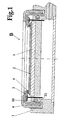
- FIG. 1 For a detailed explanation of the invention height is exemplified with FIG a device of the prior art shown.
- the inventive height consists in particular in the vertical system assembly of innovative device.
- the voltage pressure of the mounted System elements vertical-rectilinear. Accordingly, the assembly of the individual elements according to the insertion principle.
Landscapes
- Chemical & Material Sciences (AREA)
- Engineering & Computer Science (AREA)
- Materials Engineering (AREA)
- Chemical Kinetics & Catalysis (AREA)
- Electrochemistry (AREA)
- Metallurgy (AREA)
- Organic Chemistry (AREA)
- Sustainable Development (AREA)
- Life Sciences & Earth Sciences (AREA)
- Automation & Control Theory (AREA)
- Electroplating Methods And Accessories (AREA)
- Electrodes Of Semiconductors (AREA)
- Medicinal Preparation (AREA)
- Medicines Containing Plant Substances (AREA)
- Sealing Battery Cases Or Jackets (AREA)
Abstract
Description
Da die vierte Periodengruppe des chemischen Periodensystems sich in der Mitte zwischen den Metallen der ersten Gruppe und den Nichtmetallen der achten Gruppe des chemischen Periodensystems befindet, sind die Elemente der vierten Periodengruppe weder Ionen leitende Metalle noch Ionen nichtleitende Nichtmetalle, sondern quasi Halbmetalle mit sogenannten Ionen Halbleitereigenschaften.
Diese Halbleitereigenschaften machte sich die moderne Technologie zu Nutze, wodurch auf kleinstem Raum Funktionen darstellbar sind für die früher tausendfach grössere Raumdimensionen erforderlich waren.
Mittels der Galvanisiermethode werden auf die Vaferoberfläche Metallschichten aufgetragen die diesen Teil des Vafers leitend machen. Die Galvanisiermethode hat den bedeutenden Vorteil, dass die Metallablagerungen auf das Wafer aus wässriger Lösung von in destilliertem Wasser gelösten Metallsalzen erfolgen können. Spezifisch, fachbezogen werden diese Metallsalzlösungen Elektrolytlösungen genannt oder vereinfacht Elektrolyte.
Die Galvanisiermethode bietet die vielfachen Variationsmöglichkeiten für die Gestaltung der Funktionseigenschaften ( features ) der auf das Vafer aufzutragenden Metallschicht. Da Metallsalze gut wasserlöslich sind können aus den wässrigen Lösungen der Salze die verschiedenen Metalle auf das Vafer aufgetragen werden. Bezüglich der Leitfähigkeitsveränderungseigenschaften, angefangen vom weniger leitfähigen Chrom bis zu den gut leitfähigen Metallen wie Kupfer, Silber oder Gold.
Das Galvanisierungsverfahren ist optimal anwendbar, weil einige Parameter der Verfahrenstechnologie weitgehend komplikationslos variierbar sind und diese Parameter eine Auswirkung auf die Struktur der Metallbeschichtung haben.
die Konzentration des Salzgehaltes der Elektrolytbäder,
die Stromdichte und Stromspannung der über die Kathode und Anode aus einer elektrischen Stromquelle zugeführten Prozessenergie und
die Elektrolytbadtemperatur.
Die Vafergalvanisiertechnologie dagegen ist ein spezielles Anwendungsgebiet der Galvanisierung. Deren Vorzüge sind in der Praxis bewährt.
Die angewandten und bekannten Vafergalvanisiervorrichtungen Vorrichtungen, die den Stand der Technik darstellen, sind solche wie sie beispielhaft mit der Figur 1 beschrieben wird.
Die Abdichtung erfolgt üblicherweise mittels einem Abdichtungsring 3. Die Abdichtung zum Elektrolytbad gemäß dem Beispiel der Figur 1 erfolgt mittels einem O-ring 18. Gleichzeitig hat der O-ring 18 eine Art Gleitspaltführungsfunktion im Gleitspalt 21. Die Montage des O-rings 18 kann jedoch, was nachteilig ist, nur im Trockenzustand erfolgen, somit bei leerem Galvanisationsbad. Bei Mehrfachmanipulation wird das System deshalb, wegen dem Trocken-Nass-Wechsel, zwangsläufig anfällig auf Sickerläckagen des Elektrolytes. Die vorhandenen Temperaturdifferenzen spielen bei den verschiedenen spezifischen Temperaturdehnungskoeffizienten der eingesetzten Vorrichtungselemente eine bedeutende Rolle. Die erforderliche 100%-ige Dichtesicherheit verursacht, deshalb im Falle von Undichtheiten im Vorrichtungssystem, Prozessunterbrechungen.
Eine nachhaltig, gleichbleibende Produktqualität ist dann nicht gegeben und prozentual betrachtet, schlagen beim kostspieligen Rohmaterial der vorliegenden zu galvanisierenden Vafer, Fehlproduktionen, von der Kostenseite her, stark zu Buche. Eine insbesondere Schwachstelle, wie in Figur 1 zum Stande der Technik gezeigt, ist der Seitenspielraum zwischen dem Abdichtungsring 3 und der Vorrichtungsbasis 1. Die Abdichtung zwischen diesen Vorrichtungsteilen mittels dem relativ grossdimensionierten O-ring 18 hat den Nachteil,dass der O-ring zum rollen neigt oder beim Hin- und Hermanipulieren des Abdichtungsrings 3, bis zur dessen Fixierung in der finalen Position, Reibungen der O-Ringoberfläche zur Beschädigung des Rings führen können, mit der Folge, von danach auftretenden Elektrolytläckagen. Generell gesehen, ist der Seitenspielraum,Spalt 21, zwischen dem Abdichtungsring 3 und der Vorrichtungsbasis 1 eine Systemschwachstelle.
Das Einsetzen des O-rings 18 ist darüberhinaus kompliziert, weil der O-ring 18 beim Einfügen in dessen Ringnut stark gestreckt werden muß und es auch bei dieser Manipulation zur O-ringbeschädigung kommen kann.
dass die Galvanisiervorrichtung einen oberen Abdichtungsring (3) besitzt, an dessen beiden Enden je eine O-ringeinlegemulde situiert ist, für die einlegbaren O-ringe (6), am oberen Ende des Abdichtungsrings (3) und O-ring (7), am unteren Ende des Abdichtungsrings (3) und die Galvanisiervorrichtung ein weiteres unteres Abdichtungselement (10) besitzt, in der Form eines Rings oder einer Rundscheibe, mit jeweilig einer als Gegenpart zum oberen Abdichtungsring (3) positionierten Kontermulde für die Einlegbarkeit des unteren O-rings (7) und der Abdichtungsring (3) und die Abdichtungselemente (10), seitenspielraumfrei in der Basis (1) beziehungsweise dem Zwischenteil (16) eingesetzt, bei eingelegten O-ringen (6) und (7), gegeneinander gedrückt werden, wodurch ein in sich geschlossener, elektrolytdichter Bereich vorhanden ist.
- Fig.1
- zeigt vergleichsweise beispielhaft den Stand der Technik einer
Vafergalvanisiervorrichtung B.
Zur Abdichtung des Elektrolytbereichs und gleichzeitiger Zentrierung der Vaferscheibe wird ein O-ring 18 eingesetzt der, des weiteren, den Spalt 21 des Montagesystems schliesst.
Durch das Auf- und Abbewegen während der Montage der Vorrichtungselemente, insbesondere des Abdichtungsrings 3, besteht die Gefahr der Bildung von Reibungsrillen am O-ring 18 und damit verbunden die Gefahr des Durchsickerns von Elektrolytflüssigkeit. Des weiteren ist der Seitenbewegungsspielraum im Spalt 21 zu groß um die Randererfassung der Vaferscheibe exakt gleichbeibend galvanisieren zu können. Der Vaferscheibenzentrierung wird somit nicht gut genug vollzogen. Die Montage des O-rings 18 in den Nut des Zwischenteils 16 ist nicht komplikationslos, da um den O-ring 18 in die Nut einzusetzen, muß der O-ring stark gestreckt werden. Dadurch besteht die Gefahr der Deformierung des O-Rings und gegebenenfalls, der Beschädigung des O-Rings durch Reibungsrillen. - Fig.2
- zeigt die Scheibengalvanisiervorrichtung A, beispielhaft gemäß der
Erfindung, mit dem Abdichtungsring 3, der an deren beiden Enden mit
je einer Mulde versehen ist. In diesen Mulden sind die O-ringe 6 und
7 eingelegt, beziehungsweise kann der O-ring 7 in die Mulde von
Abdichtungsring oder Abdichtungsscheibe 10 gelegt werden. Der
Abdichtungsring 3 wird seitenspielraumfrei und exakt zentriert an das
Zwischenteil 16 montiert.
Gegenpart zum Abdichtungsring 3, zur Abdichtung des Elektrolytbereichs sind der untere Abdichtungsring beziehungsweise die Abdichtungsscheibe 10, mit im Randbereich situierter O-ringmulde, jeweils kontrabezogen zur unteren Ringmulde des Abdichtungsrings 3.
Im Falle der Anwendung eines unteren Abdichtungsrings 10, ist dieser mittels einem elastischen Faltenbalg, zwecks der Elektrolytabdichtung, mit der Vorrichtungsbasis verbunden. Im Falle von Figur 2, mit einem Faltenbalg 9 in waagerechter Position. Zwischen Abdichtungsring 10 und der Vorrichtungsbasis 1 ist ein pufferndes, elastisches Ringelement 8 situiert,zum Zwecke der Spannungsnivelierung des gesamten Vorrichtungselementesystems. - Fig.3
- zeigt eine Variante der Vorrichtungsgestaltung C, wie in Figur 2,
unter Anwendung eines offenen unteren Abdichtungsrings 10.
Der Abdichtungsring 10 ist mittels einem senkrechten Faltenbalg 9 mit der Vorrichtungsbasis verbunden um die Elektrolytdichtheit zu gewähr leisten. Der elastische Pufferring 8 ist entsprechend in Stützformation höher und gestattet zusammen mit dem senkrechten Faltenbalg eine, für Bedarfsfälle, höhere Vorrichtungsgestaltung.
Bei dieser Vorrichtungsvariante erfolgt der Elementeverbunddruck auf die beiden O-ringe 6 und 7 mittels der überwurfmutter 4. - Fig.4
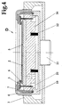
- zeigt eine Vorrichtungsvariante D, unter Anwendung einer geschlossenen
vollflächigen Abdichtungsscheibe 10, als Konterpart zum Abdichtungsring
3. Der O-ring 7 wird vorzugsweise in die O-ringmulde der
Abdichtungsscheibe 10 eingelegt. Zum Abfedern der Andruckkraft auf
die Scheibe10, kommt ein abpufferndes elastisches Ringelement 12
zum Einsatz.
Das Andrücken der Abdichtungsscheibe 10 an den Abdichtungsring 3 mit den einliegenden O-ringen 6 und 7 erfolgt mittels einer Druckvorrichtung 11, die mechanisch, pneumatisch oder hydraulisch betrieben werden kann. - Fig.5
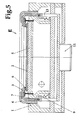
- zeigt eine Vorrichtungsvariante E,als Kombination der Figuren 3 und 4 mit einem Höhenvariationszwischenelement 13 zur Höhendimensions variation der Gesamtvorrichtung.
- Fig.6
- zeigt eine Vorrichtungsvariante F mit beiderseitigem Faltenbalg 9,
der in dieser Form einen geschlossenen Kanal 14 bildet, der
neben der Funktion als Elektrolytabdichtungselement, gleichzeitig
einen Kanal 14 darstellt ,für die Zuleitung der Hydraulik- beziehungsweise
Pneumatikmedien als Druckmedien beim regulierten Andrücken
des unteren Abdichtungsrings 10, an den oberen Abdichtungsring 3.
Diese Variante hat den Vorteil, dass die beiden O-Ringe 6 und 7, nach deren Vorfixierung, keiner weiteren mechanischen Manipulation unterworfen sind, insbesondere, weil das O-ringesystem stets in vertikaler Richtung belastet wird.
Der Abdichtungsdruck auf die beiden O-Ringe 6 und 7 erfolgt in diesem Falle dynamisch. Die O-ringe unterliegen somit keiner Reibungsbelastung.
Ein weiterer Vorteil ist es, dass bei einer Prozess-änderung oder einem sonstigen erforderlichen Prozessunterbruch die O-ringe leicht dem System entnommen werden und wieder leicht eingesetzt werden können. Der O-ringeverschleiß ist damit sehr gering.
Diese Variante trägt noch mehr zur Abdichtungssicherheit des Elektrolytmediums bei. - Fig.7
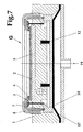
- zeigt eine Vorrichtungsvariante G, eine Kombinationsvariante auf der
Basis der Figuren 2 und 6.
Durch die Anwendung einer Flächenmembran 17 wird der Druck auf die Bodenfläche der Abdichtungsscheibe 10 am gleichmässigsten übertragen. Damit wird die schonendste und gleichmässigste Druckverteilung einwirkend auf die beiden Abdichtungsringe 6 und 7 erreicht. Hinzu kommt noch die puffernde Wirkung der elastischen Elemente 8. Alle Elemente der gesamtem Galvanisiervorrichtung werden somit ideal zentrisch verbunden und dynamisch verspannt.
- 1
- Vorrichtungsbasis (Substrataufnahme)
- 2
- Vafer (Galvanisierungssubstrat)
- 3
- Abdichtungsring
- 4
- überwurfmutter
- 5
- Adapter
- 6
- Oberer O-ring
- 7
- Unterer O-ring
- 8
- Elastisches Pufferelement als Stütze bei Höhenvariation
- 9
- Faltenbalg
- 10
- Unterer Abdichtungsring beziehungsweise Fläche
- 11
- Druckelement
- 12
- Elastisches Element wie 8
- 13
- Höhenvariationszwischenelement
- 14
- Druckmedienkanal
- 15
- Doppelter Faltenbalg
- 16
- Zwischenteil
- 17
- Elastische Membran
- 18
- O-ring zum Stand der Technik
- 19
- Druckausübendes Medium
- 20
- Stromzuführung
- 21
- Spalt zwischen 1 und 3
- A
- Galvanisiervorrichtung gemäß dem Stande der Technik
- B bis G
- Erfinderische Varianten der Galvanisiervorrichtung
Claims (7)
- Galvanisiervorrichtung zum Galvanisieren von Vaferscheiben, bestehend aus; Vorrichtungsbasis mit Innengewinde (1), einer überwurfmutter (4), zur Befestigung und Fixierung des Gesamtsystems der Vorrichtung, einem Adapter (5), als Aufnahmebasis für die zu galvanisierenden Vaferscheiben und Abdichtungselementen zum Abdichten des Elektrolytbereichs,
dadurch gekennzeichnet, dass;
die Galvanisiervorrichtung einen oberen Abdichtungsring (3) besitzt, an dessen beiden Enden je eine O-ringeinlegemulde situiert ist, für die einlegbaren O-ringe (6), am oberen Ende des Abdichtungsrings (3) und O-ring (7), am unteren Ende des Abdichtungsrings (3) und die Galvanisiervorrichtung ein weiteres unteres Abdichtungselement (10) besitzt, in der Form eines Rings oder einer Rundscheibe, mit jeweilig einer als Gegenpart zum oberen Abdichtungsring (3) positionierten Kontermulde für die Einlegbarkeit des unteren O-rings (7) und der Abdichtungsring (3) und die Abdichtungselemente (10), seitenspielraumfrei in der Basis (1) beziehungsweise dem Zwischenteil (16) eingesetzt, bei eingelegten O-ringen (6) und (7), gegeneinander gedrückt werden, wodurch ein in sich geschlossener, elektrolytdichter Bereich vorhanden ist. - Galvanisiervorrichtung, nach Anspruch 1, dadurch gekennzeichnet, dass das Gegeneinanderdrücken eines der Abdichtungselemente (10) gegen den Abdichtungsring (3), bei eingelegten O-ringen, mittels Anwendung von pneumatischen beziehungsweise hydraulischen Drucksystemen erfolgt.
- Galvanisiervorrichtung, nach den Ansprüchen 1 und 2,
dadurch gekennzeichnet, dass bei Anwendung der pneumatischen oder hydraulischen Drucksysteme unter Anwendung eines Abdichtungsrings (10) mit eingelegtem O-ring (7) als unteren Konterpart zu Abdichtungsring (3), die Zuführung der Druckmedien der hydraulischen beziehungsweise pneumatischen Druckmedien, mittels einem Durchlaufkanal (14) bestehend aus einem abdichtenden Doppelfaltenbalg (15) erfolgt. - Galvanisiervorrichtung, nach den Ansprüchen 1 und 2,
dadurch gekennzeichnet, dass bei Anwendung der pneumatischen Drucksysteme unter Anwendung einer Abdichtungsscheibe (10) mit eingelegtem O-ring (7) als unteren Konterpart zu Abdichtungsring (3), die Zuführung der Druckmedien der hydraulischen beziehungsweise pneumatischen Druckmedien auf eine flexible Membran (17), flächenbezogen erfolgt, wodurch der Abdichtungsring (3) und die Abdichtungsscheibe (10) dynamisch und intergral gleichmässig gegeneinander gedrückt werden. - Galvanisiervorrichtung, nach den Ansprüchen 1, 3 und 4,
dadurch gekennzeichnet, dass die regulierte Druckmedienzufuhr mittels einem Regelaggregat erfolgt, das die O-ringbelastung derart berücksichtigt, dass der O-ring nicht deformiert wird wodurch eine optimale Abdichtung gewährleistet ist. - Galvanisiervorrichtung, nach Anspruch 1, dadurch gekennzeichnet, dass Stütz-Pufferelemente (8) und (12) einsetzbar sind, die die Belastung der O-ringe beim Verspannen abfedern und eine höhendifferenzierte Vorrichtungsgestaltung begünstigen.
- Galvaniservorrichtung, nach Anspruch 1, dadurch gekennzeichnet, dass, bei den variablen und differenten Vorrichtungsgestaltungsmöglichkeiten, Faltenbalgsysteme (9) zur Abdichtung des Elektrolytbereichs einsetzbar sind.
Applications Claiming Priority (2)
| Application Number | Priority Date | Filing Date | Title |
|---|---|---|---|
| DE10333068A DE10333068A1 (de) | 2003-07-19 | 2003-07-19 | Scheibengalvanikvorrichtung |
| DE10333068 | 2003-07-19 |
Publications (3)
| Publication Number | Publication Date |
|---|---|
| EP1510601A1 true EP1510601A1 (de) | 2005-03-02 |
| EP1510601B1 EP1510601B1 (de) | 2006-03-01 |
| EP1510601B9 EP1510601B9 (de) | 2006-11-15 |
Family
ID=34042003
Family Applications (1)
| Application Number | Title | Priority Date | Filing Date |
|---|---|---|---|
| EP04016833A Expired - Lifetime EP1510601B9 (de) | 2003-07-19 | 2004-07-16 | Scheibengalvanisiervorrichtung |
Country Status (6)
| Country | Link |
|---|---|
| US (1) | US20050045473A1 (de) |
| EP (1) | EP1510601B9 (de) |
| CN (1) | CN100339511C (de) |
| AT (1) | ATE318945T1 (de) |
| CA (1) | CA2474830A1 (de) |
| DE (2) | DE10333068A1 (de) |
Families Citing this family (3)
| Publication number | Priority date | Publication date | Assignee | Title |
|---|---|---|---|---|
| US20130306465A1 (en) * | 2012-05-17 | 2013-11-21 | Applied Materials, Inc. | Seal rings in electrochemical processors |
| JP6713916B2 (ja) * | 2016-12-01 | 2020-06-24 | 株式会社荏原製作所 | 基板ホルダ、めっき装置、及び基板ホルダの製造方法 |
| CN109158713B (zh) * | 2018-09-27 | 2024-05-07 | 格林美(武汉)城市矿产循环产业园开发有限公司 | 一种继电器螺纹微镀修复定位装置 |
Citations (6)
| Publication number | Priority date | Publication date | Assignee | Title |
|---|---|---|---|---|
| US5405518A (en) * | 1994-04-26 | 1995-04-11 | Industrial Technology Research Institute | Workpiece holder apparatus |
| WO2000032848A2 (en) * | 1998-11-30 | 2000-06-08 | Applied Materials, Inc. | An inflatable compliant bladder assembly |
| US6080291A (en) * | 1998-07-10 | 2000-06-27 | Semitool, Inc. | Apparatus for electrochemically processing a workpiece including an electrical contact assembly having a seal member |
| DE19923871A1 (de) * | 1999-05-25 | 2000-12-07 | Rossendorf Forschzent | Einrichtung zur abgedichteten Halterung dünner Scheiben |
| US20030132118A1 (en) * | 2002-01-14 | 2003-07-17 | Applied Materials, Inc. | Electroplating of semiconductor wafers |
| US20030132105A1 (en) * | 1998-09-08 | 2003-07-17 | Hui Wang | Methods and apparatus for holding and positioning semiconductor workpieces during electropolishing and/or electroplating of the workpieces |
Family Cites Families (8)
| Publication number | Priority date | Publication date | Assignee | Title |
|---|---|---|---|---|
| JP3578811B2 (ja) * | 1994-10-12 | 2004-10-20 | シチズン時計株式会社 | 半導体ウエハーのメッキ方法 |
| US5578167A (en) * | 1996-01-31 | 1996-11-26 | Motorola, Inc. | Substrate holder and method of use |
| JP3106418B2 (ja) * | 1996-07-30 | 2000-11-06 | 株式会社東京精密 | 研磨装置 |
| JP3366193B2 (ja) * | 1996-09-10 | 2003-01-14 | ヤマハ発動機株式会社 | 表面処理装置におけるシール装置 |
| US6673216B2 (en) * | 1999-08-31 | 2004-01-06 | Semitool, Inc. | Apparatus for providing electrical and fluid communication to a rotating microelectronic workpiece during electrochemical processing |
| JP2001158993A (ja) * | 1999-11-30 | 2001-06-12 | Honda Motor Co Ltd | 筒状部材のメッキ装置 |
| JP2001260065A (ja) * | 2000-03-17 | 2001-09-25 | Advantest Corp | 部品保持装置 |
| US7147232B2 (en) * | 2003-06-30 | 2006-12-12 | Hydra-Lock Corporation | Workpiece holder |
-
2003
- 2003-07-19 DE DE10333068A patent/DE10333068A1/de not_active Withdrawn
-
2004
- 2004-07-16 CA CA002474830A patent/CA2474830A1/en not_active Abandoned
- 2004-07-16 AT AT04016833T patent/ATE318945T1/de not_active IP Right Cessation
- 2004-07-16 DE DE502004000318T patent/DE502004000318D1/de not_active Expired - Lifetime
- 2004-07-16 EP EP04016833A patent/EP1510601B9/de not_active Expired - Lifetime
- 2004-07-19 US US10/894,161 patent/US20050045473A1/en not_active Abandoned
- 2004-07-19 CN CNB2004100851753A patent/CN100339511C/zh not_active Expired - Fee Related
Patent Citations (6)
| Publication number | Priority date | Publication date | Assignee | Title |
|---|---|---|---|---|
| US5405518A (en) * | 1994-04-26 | 1995-04-11 | Industrial Technology Research Institute | Workpiece holder apparatus |
| US6080291A (en) * | 1998-07-10 | 2000-06-27 | Semitool, Inc. | Apparatus for electrochemically processing a workpiece including an electrical contact assembly having a seal member |
| US20030132105A1 (en) * | 1998-09-08 | 2003-07-17 | Hui Wang | Methods and apparatus for holding and positioning semiconductor workpieces during electropolishing and/or electroplating of the workpieces |
| WO2000032848A2 (en) * | 1998-11-30 | 2000-06-08 | Applied Materials, Inc. | An inflatable compliant bladder assembly |
| DE19923871A1 (de) * | 1999-05-25 | 2000-12-07 | Rossendorf Forschzent | Einrichtung zur abgedichteten Halterung dünner Scheiben |
| US20030132118A1 (en) * | 2002-01-14 | 2003-07-17 | Applied Materials, Inc. | Electroplating of semiconductor wafers |
Also Published As
| Publication number | Publication date |
|---|---|
| EP1510601B9 (de) | 2006-11-15 |
| ATE318945T1 (de) | 2006-03-15 |
| CN1614100A (zh) | 2005-05-11 |
| DE10333068A1 (de) | 2005-02-10 |
| CA2474830A1 (en) | 2005-01-19 |
| CN100339511C (zh) | 2007-09-26 |
| DE502004000318D1 (de) | 2006-04-27 |
| US20050045473A1 (en) | 2005-03-03 |
| EP1510601B1 (de) | 2006-03-01 |
Similar Documents
| Publication | Publication Date | Title |
|---|---|---|
| EP3312871B1 (de) | Aufnahmeeinrichtung zur aufnahme eines substratstapels | |
| DE10208414B4 (de) | Vorrichtung mit einem verbesserten Polierkissenaufbereiter für das chemisch mechanische Polieren | |
| CH659484A5 (de) | Anordnung zur beschichtung von substraten mittels kathodenzerstaeubung. | |
| EP2985497B1 (de) | Verschlusselement für ein Vakuumventil mit abgepresster, aufvulkanisierter Dichtung | |
| CH665058A5 (de) | Vorrichtung zur waermebehandlung von halbleiterplaettchen durch waermeuebertragung mittels gas. | |
| EP3592697B1 (de) | Vorrichtung und verfahren zum bereitstellen einer vielzahl von nanodrähten | |
| EP2152939A1 (de) | Vorrichtung und verfahren zur elektrische kontaktierung von ebenem gut in durchlaufanlagen | |
| EP3659408A1 (de) | Verfahren, vorrichtung und anlage zur leiterplattenherstellung | |
| WO2009129989A1 (de) | Einrichtung und verfahren zur behandlung von silizium-wafern oder flachen gegenständen | |
| EP1510601B1 (de) | Scheibengalvanisiervorrichtung | |
| DE3435019A1 (de) | Maskenringanordnung fuer roentgenstrahlenlithographie | |
| EP0741804A1 (de) | Verfahren und vorrichtung zum elektrolytischen metallisieren oder ätzen von behandlungsgut | |
| EP1910590B1 (de) | Einrichtung zur behandlung von substraten, insbesondere zur galvanisierung von substraten | |
| DE10319379A1 (de) | Vorrichtung zum Transportieren eines flachen Substrats in einer Vakuumkammer | |
| DE19605599C1 (de) | Vorrichtung zum Transport von Substraten | |
| DE10261306B4 (de) | Haltering mit reduzierter Abnutzungs- und Kontaminationsrate für einen Polierkopf einer CMP-Anlage und Polierkopf und CMP-Vorrichtung mit Haltering | |
| DE102005045717B3 (de) | Träger für ein Substrat | |
| DE102009046750A1 (de) | Elektrochemisches Einebnungssystem mit verbesserter Elektrolytströmung | |
| DE102013104469B4 (de) | Vorrichtung zur großflächigen elektrischen und/oder thermischen Kontaktierung eines Wafers | |
| EP1961706B1 (de) | Vorrichtung zur elektrochemischen verarbeitung von wasser | |
| DE10062496A1 (de) | Halter für flache Werkstücke, insbesondere Halbleiterwafer | |
| DE102006033354B4 (de) | Vorrichtung zum Behandeln von flachen, zerbrechlichen Substraten | |
| DE102017104333B3 (de) | Zentrieranordnung, Ventilanordnung, Vakuumanordnung und Verfahren | |
| DE10249572A1 (de) | Vorrichtung zum galvanischen Beschichten | |
| EP3190212B1 (de) | Vorrichtung zur oberflächenbehandlung eines endlosmaterials sowie deren verwendung |
Legal Events
| Date | Code | Title | Description |
|---|---|---|---|
| PUAI | Public reference made under article 153(3) epc to a published international application that has entered the european phase |
Free format text: ORIGINAL CODE: 0009012 |
|
| 17P | Request for examination filed |
Effective date: 20041228 |
|
| AK | Designated contracting states |
Kind code of ref document: A1 Designated state(s): AT BE BG CH CY CZ DE DK EE ES FI FR GB GR HU IE IT LI LU MC NL PL PT RO SE SI SK TR |
|
| AX | Request for extension of the european patent |
Extension state: AL HR LT LV MK |
|
| 17Q | First examination report despatched |
Effective date: 20050429 |
|
| GRAP | Despatch of communication of intention to grant a patent |
Free format text: ORIGINAL CODE: EPIDOSNIGR1 |
|
| GRAS | Grant fee paid |
Free format text: ORIGINAL CODE: EPIDOSNIGR3 |
|
| AKX | Designation fees paid |
Designated state(s): AT BE BG CH CY CZ DE DK EE ES FI FR GB GR HU IE IT LI LU MC NL PL PT RO SE SI SK TR |
|
| GRAA | (expected) grant |
Free format text: ORIGINAL CODE: 0009210 |
|
| AK | Designated contracting states |
Kind code of ref document: B1 Designated state(s): AT BE BG CH CY CZ DE DK EE ES FI FR GB GR HU IE IT LI LU MC NL PL PT RO SE SI SK TR |
|
| PG25 | Lapsed in a contracting state [announced via postgrant information from national office to epo] |
Ref country code: NL Free format text: LAPSE BECAUSE OF FAILURE TO SUBMIT A TRANSLATION OF THE DESCRIPTION OR TO PAY THE FEE WITHIN THE PRESCRIBED TIME-LIMIT Effective date: 20060301 Ref country code: IE Free format text: LAPSE BECAUSE OF FAILURE TO SUBMIT A TRANSLATION OF THE DESCRIPTION OR TO PAY THE FEE WITHIN THE PRESCRIBED TIME-LIMIT Effective date: 20060301 Ref country code: IT Free format text: LAPSE BECAUSE OF FAILURE TO SUBMIT A TRANSLATION OF THE DESCRIPTION OR TO PAY THE FEE WITHIN THE PRESCRIBED TIME-LIMIT;WARNING: LAPSES OF ITALIAN PATENTS WITH EFFECTIVE DATE BEFORE 2007 MAY HAVE OCCURRED AT ANY TIME BEFORE 2007. THE CORRECT EFFECTIVE DATE MAY BE DIFFERENT FROM THE ONE RECORDED. Effective date: 20060301 Ref country code: SI Free format text: LAPSE BECAUSE OF FAILURE TO SUBMIT A TRANSLATION OF THE DESCRIPTION OR TO PAY THE FEE WITHIN THE PRESCRIBED TIME-LIMIT Effective date: 20060301 Ref country code: SK Free format text: LAPSE BECAUSE OF FAILURE TO SUBMIT A TRANSLATION OF THE DESCRIPTION OR TO PAY THE FEE WITHIN THE PRESCRIBED TIME-LIMIT Effective date: 20060301 Ref country code: PL Free format text: LAPSE BECAUSE OF FAILURE TO SUBMIT A TRANSLATION OF THE DESCRIPTION OR TO PAY THE FEE WITHIN THE PRESCRIBED TIME-LIMIT Effective date: 20060301 Ref country code: GB Free format text: LAPSE BECAUSE OF FAILURE TO SUBMIT A TRANSLATION OF THE DESCRIPTION OR TO PAY THE FEE WITHIN THE PRESCRIBED TIME-LIMIT Effective date: 20060301 Ref country code: FI Free format text: LAPSE BECAUSE OF FAILURE TO SUBMIT A TRANSLATION OF THE DESCRIPTION OR TO PAY THE FEE WITHIN THE PRESCRIBED TIME-LIMIT Effective date: 20060301 Ref country code: RO Free format text: LAPSE BECAUSE OF FAILURE TO SUBMIT A TRANSLATION OF THE DESCRIPTION OR TO PAY THE FEE WITHIN THE PRESCRIBED TIME-LIMIT Effective date: 20060301 |
|
| REG | Reference to a national code |
Ref country code: GB Ref legal event code: FG4D Free format text: NOT ENGLISH |
|
| REG | Reference to a national code |
Ref country code: CH Ref legal event code: EP |
|
| REG | Reference to a national code |
Ref country code: IE Ref legal event code: FG4D Free format text: LANGUAGE OF EP DOCUMENT: GERMAN |
|
| REF | Corresponds to: |
Ref document number: 502004000318 Country of ref document: DE Date of ref document: 20060427 Kind code of ref document: P |
|
| PG25 | Lapsed in a contracting state [announced via postgrant information from national office to epo] |
Ref country code: SE Free format text: LAPSE BECAUSE OF FAILURE TO SUBMIT A TRANSLATION OF THE DESCRIPTION OR TO PAY THE FEE WITHIN THE PRESCRIBED TIME-LIMIT Effective date: 20060601 Ref country code: BG Free format text: LAPSE BECAUSE OF FAILURE TO SUBMIT A TRANSLATION OF THE DESCRIPTION OR TO PAY THE FEE WITHIN THE PRESCRIBED TIME-LIMIT Effective date: 20060601 Ref country code: DK Free format text: LAPSE BECAUSE OF FAILURE TO SUBMIT A TRANSLATION OF THE DESCRIPTION OR TO PAY THE FEE WITHIN THE PRESCRIBED TIME-LIMIT Effective date: 20060601 |
|
| PG25 | Lapsed in a contracting state [announced via postgrant information from national office to epo] |
Ref country code: ES Free format text: LAPSE BECAUSE OF FAILURE TO SUBMIT A TRANSLATION OF THE DESCRIPTION OR TO PAY THE FEE WITHIN THE PRESCRIBED TIME-LIMIT Effective date: 20060612 |
|
| PG25 | Lapsed in a contracting state [announced via postgrant information from national office to epo] |
Ref country code: MC Free format text: LAPSE BECAUSE OF NON-PAYMENT OF DUE FEES Effective date: 20060731 Ref country code: BE Free format text: LAPSE BECAUSE OF NON-PAYMENT OF DUE FEES Effective date: 20060731 |
|
| PG25 | Lapsed in a contracting state [announced via postgrant information from national office to epo] |
Ref country code: PT Free format text: LAPSE BECAUSE OF FAILURE TO SUBMIT A TRANSLATION OF THE DESCRIPTION OR TO PAY THE FEE WITHIN THE PRESCRIBED TIME-LIMIT Effective date: 20060801 |
|
| NLV1 | Nl: lapsed or annulled due to failure to fulfill the requirements of art. 29p and 29m of the patents act | ||
| GBV | Gb: ep patent (uk) treated as always having been void in accordance with gb section 77(7)/1977 [no translation filed] |
Effective date: 20060301 |
|
| REG | Reference to a national code |
Ref country code: IE Ref legal event code: FD4D |
|
| PLBE | No opposition filed within time limit |
Free format text: ORIGINAL CODE: 0009261 |
|
| STAA | Information on the status of an ep patent application or granted ep patent |
Free format text: STATUS: NO OPPOSITION FILED WITHIN TIME LIMIT |
|
| 26N | No opposition filed |
Effective date: 20061204 |
|
| REG | Reference to a national code |
Ref country code: GB Ref legal event code: 710B Free format text: EXTENSION APPLICATION: APPLICATION FOR EXTENSION OF THE PERIOD(S) PRESCRIBED BY RULE(S) SCHEDULE 4 PARA 2 FILED ON 20070314 |
|
| EN | Fr: translation not filed | ||
| GBT | Gb: translation of ep patent filed (gb section 77(6)(a)/1977) |
Effective date: 20070621 |
|
| REG | Reference to a national code |
Ref country code: GB Ref legal event code: 9110 Free format text: EXTENSION ALLOWED: PERIOD(S) PRESCRIBED BY RULE(S) SCHEDULE 4 PARA 2 EXTENDED UNDER RULE 110(6) IN ACCORDANCE WITH THE DECISION OF THE COMPTROLLER DATED 20070502. THE PATENT/APPLICATION IS REINSTATED SUBJECT TO SPECIAL TERMS FOR THIRD PARTY INTERESTS. |
|
| PG25 | Lapsed in a contracting state [announced via postgrant information from national office to epo] |
Ref country code: AT Free format text: LAPSE BECAUSE OF NON-PAYMENT OF DUE FEES Effective date: 20060716 |
|
| BERE | Be: lapsed |
Owner name: RENA SONDERMASCHINEN G.M.B.H. Effective date: 20060731 |
|
| PG25 | Lapsed in a contracting state [announced via postgrant information from national office to epo] |
Ref country code: CZ Free format text: LAPSE BECAUSE OF FAILURE TO SUBMIT A TRANSLATION OF THE DESCRIPTION OR TO PAY THE FEE WITHIN THE PRESCRIBED TIME-LIMIT Effective date: 20060301 Ref country code: FR Free format text: LAPSE BECAUSE OF FAILURE TO SUBMIT A TRANSLATION OF THE DESCRIPTION OR TO PAY THE FEE WITHIN THE PRESCRIBED TIME-LIMIT Effective date: 20070309 Ref country code: GR Free format text: LAPSE BECAUSE OF FAILURE TO SUBMIT A TRANSLATION OF THE DESCRIPTION OR TO PAY THE FEE WITHIN THE PRESCRIBED TIME-LIMIT Effective date: 20060602 |
|
| PG25 | Lapsed in a contracting state [announced via postgrant information from national office to epo] |
Ref country code: EE Free format text: LAPSE BECAUSE OF FAILURE TO SUBMIT A TRANSLATION OF THE DESCRIPTION OR TO PAY THE FEE WITHIN THE PRESCRIBED TIME-LIMIT Effective date: 20060301 |
|
| PG25 | Lapsed in a contracting state [announced via postgrant information from national office to epo] |
Ref country code: TR Free format text: LAPSE BECAUSE OF FAILURE TO SUBMIT A TRANSLATION OF THE DESCRIPTION OR TO PAY THE FEE WITHIN THE PRESCRIBED TIME-LIMIT Effective date: 20060301 Ref country code: HU Free format text: LAPSE BECAUSE OF FAILURE TO SUBMIT A TRANSLATION OF THE DESCRIPTION OR TO PAY THE FEE WITHIN THE PRESCRIBED TIME-LIMIT Effective date: 20060902 Ref country code: LU Free format text: LAPSE BECAUSE OF NON-PAYMENT OF DUE FEES Effective date: 20060716 |
|
| PGFP | Annual fee paid to national office [announced via postgrant information from national office to epo] |
Ref country code: CH Payment date: 20080731 Year of fee payment: 5 |
|
| PG25 | Lapsed in a contracting state [announced via postgrant information from national office to epo] |
Ref country code: FR Free format text: LAPSE BECAUSE OF FAILURE TO SUBMIT A TRANSLATION OF THE DESCRIPTION OR TO PAY THE FEE WITHIN THE PRESCRIBED TIME-LIMIT Effective date: 20060301 Ref country code: CY Free format text: LAPSE BECAUSE OF FAILURE TO SUBMIT A TRANSLATION OF THE DESCRIPTION OR TO PAY THE FEE WITHIN THE PRESCRIBED TIME-LIMIT Effective date: 20060301 |
|
| PGFP | Annual fee paid to national office [announced via postgrant information from national office to epo] |
Ref country code: GB Payment date: 20080714 Year of fee payment: 5 |
|
| REG | Reference to a national code |
Ref country code: CH Ref legal event code: PL |
|
| GBPC | Gb: european patent ceased through non-payment of renewal fee |
Effective date: 20090716 |
|
| PG25 | Lapsed in a contracting state [announced via postgrant information from national office to epo] |
Ref country code: CH Free format text: LAPSE BECAUSE OF NON-PAYMENT OF DUE FEES Effective date: 20090731 Ref country code: LI Free format text: LAPSE BECAUSE OF NON-PAYMENT OF DUE FEES Effective date: 20090731 |
|
| PG25 | Lapsed in a contracting state [announced via postgrant information from national office to epo] |
Ref country code: GB Free format text: LAPSE BECAUSE OF NON-PAYMENT OF DUE FEES Effective date: 20090716 |
|
| REG | Reference to a national code |
Ref country code: DE Ref legal event code: R084 Ref document number: 502004000318 Country of ref document: DE |
|
| REG | Reference to a national code |
Ref country code: DE Ref legal event code: R084 Ref document number: 502004000318 Country of ref document: DE |
|
| REG | Reference to a national code |
Ref country code: DE Ref legal event code: R084 Ref document number: 502004000318 Country of ref document: DE Effective date: 20110616 |
|
| PGFP | Annual fee paid to national office [announced via postgrant information from national office to epo] |
Ref country code: DE Payment date: 20140127 Year of fee payment: 10 |
|
| REG | Reference to a national code |
Ref country code: DE Ref legal event code: R119 Ref document number: 502004000318 Country of ref document: DE |
|
| PG25 | Lapsed in a contracting state [announced via postgrant information from national office to epo] |
Ref country code: DE Free format text: LAPSE BECAUSE OF NON-PAYMENT OF DUE FEES Effective date: 20150203 |
|
| REG | Reference to a national code |
Ref country code: DE Ref legal event code: R119 Ref document number: 502004000318 Country of ref document: DE Effective date: 20150203 |