EP1510448A1 - Nabenlichtmaschine für Fahrrad - Google Patents
Nabenlichtmaschine für Fahrrad Download PDFInfo
- Publication number
- EP1510448A1 EP1510448A1 EP04020398A EP04020398A EP1510448A1 EP 1510448 A1 EP1510448 A1 EP 1510448A1 EP 04020398 A EP04020398 A EP 04020398A EP 04020398 A EP04020398 A EP 04020398A EP 1510448 A1 EP1510448 A1 EP 1510448A1
- Authority
- EP
- European Patent Office
- Prior art keywords
- hub
- wiring
- bicycle
- shaft
- wiring unit
- Prior art date
- Legal status (The legal status is an assumption and is not a legal conclusion. Google has not performed a legal analysis and makes no representation as to the accuracy of the status listed.)
- Granted
Links
- 230000005611 electricity Effects 0.000 claims abstract description 44
- 239000000725 suspension Substances 0.000 description 7
- 210000000078 claw Anatomy 0.000 description 3
- 238000012423 maintenance Methods 0.000 description 2
- 229910052751 metal Inorganic materials 0.000 description 2
- 239000002184 metal Substances 0.000 description 2
- 239000011347 resin Substances 0.000 description 2
- 229920005989 resin Polymers 0.000 description 2
- 241001391944 Commicarpus scandens Species 0.000 description 1
- 229910000831 Steel Inorganic materials 0.000 description 1
- VNTLIPZTSJSULJ-UHFFFAOYSA-N chromium molybdenum Chemical compound [Cr].[Mo] VNTLIPZTSJSULJ-UHFFFAOYSA-N 0.000 description 1
- 239000000356 contaminant Substances 0.000 description 1
- 238000002788 crimping Methods 0.000 description 1
- 230000007423 decrease Effects 0.000 description 1
- 239000004519 grease Substances 0.000 description 1
- 229910001095 light aluminium alloy Inorganic materials 0.000 description 1
- 238000012986 modification Methods 0.000 description 1
- 230000004048 modification Effects 0.000 description 1
- 230000002093 peripheral effect Effects 0.000 description 1
- 239000010959 steel Substances 0.000 description 1
Images


Classifications
-
- B—PERFORMING OPERATIONS; TRANSPORTING
- B62—LAND VEHICLES FOR TRAVELLING OTHERWISE THAN ON RAILS
- B62J—CYCLE SADDLES OR SEATS; AUXILIARY DEVICES OR ACCESSORIES SPECIALLY ADAPTED TO CYCLES AND NOT OTHERWISE PROVIDED FOR, e.g. ARTICLE CARRIERS OR CYCLE PROTECTORS
- B62J6/00—Arrangement of optical signalling or lighting devices on cycles; Mounting or supporting thereof; Circuits therefor
- B62J6/06—Arrangement of lighting dynamos or drives therefor
- B62J6/12—Dynamos arranged in the wheel hub
Definitions
- the present invention relates to a bicycle hub generator. More specifically, the present invention relates to a bicycle hub generator provided in a center portion of a wheel of a bicycle configured to deliver electric power to an external device mounted to the bicycle.
- a conventional hub provided at a center portion of a wheel of a bicycle generally includes a hub shaft, a hub body and a bearing.
- the hub shaft is mounted in a freely detachable but non-rotatable manner to the frame (e.g., front fork or chain stay) of the bicycle.
- the hub body is mounted in a freely rotatable manner to the hub shaft.
- the bearing is configured to support the hub body in a freely rotatable manner on the hub shaft.
- the hub body usually has a pair of hub flanges, i.e., one on the outer circumference of each end of the hub body, configured such that the spokes of the wheel can be hooked thereto.
- the conventional bicycle hub explained above is sometimes equipped with a hub generator such as the one disclosed in the Japanese Laid-Open Utility Model Patent Publication No. 48-103805 (microfilm of Utility Model Patent Application No. 47-028241).
- the hub generator disclosed in the above mentioned reference has an electricity generating mechanism that is built into the hub body to serve as an electric power source for a lamp or other external device of the bicycle.
- electricity can be generated without contacting or sliding against a rotating portion.
- the electric generating efficiency improves and the wheel rotation loss decreases in comparison with electricity generating devices that contact the rim of the wheel.
- a conventional hub generator uses wires to deliver the electric power generated by the electricity generating mechanism to the lamp or other external device of the bicycle.
- the wires pass not along the outer circumference of the hub shaft but through a hole formed through the center of the hub shaft and the wires are drawn out from the end of the hub shaft.
- the wires are passed through the inside of the hub shaft. Therefore, it is easier to protect the wires than a case in which the wires are passed along the outside circumference of the hub shaft.
- the wires that are drawn out from the end of the hub shaft are exposed to the outside, the wires are not protected and could possibly be broken.
- a feasible solution is to provide a cover member on the end of the hub shaft to cover the wires drawn out from the end of the hub shaft.
- a separate mounting structure is required and the structure of the hub generator becomes more complex.
- One object of the present invention is to provide a bicycle hub generator that can protect the wires drawn out from the end of the hub shaft with a simple structure.
- a bicycle hub generator comprising a hub shaft, a hub body, an electricity generating mechanism, a wiring unit, a wiring passage and a wiring draw-out part.
- the hub shaft has first and second shaft ends with first and second connecting members, respectively, adapted to be coupled to a frame of the bicycle.
- the hub body is coupled to the hub shaft such that the hub body rotates freely with respect to the hub shaft.
- the electricity generating mechanism is disposed between the hub body and the hub shaft.
- the electricity generating mechanism is configured and arranged to generate electricity using a relative rotation of the hub body with respect to the hub shaft.
- the wiring unit is coupled to the electricity generating mechanism and configured and arranged to be coupled to an external bicycle device for supplying the electricity to the external bicycle device.
- the wiring passage extends inside the hub shaft between the electricity generating mechanism and the first shaft end such that the wiring unit passes through the wiring passage from the electricity generating mechanism and extends out from the first shaft end.
- the wiring draw-out part is coupled to the first connecting member at the first shaft end.
- the wiring draw-out part is configured and arranged to guide the wiring unit from the first shaft end to outside of the wiring draw-out part.
- the portion of the wiring unit that extends through the wiring passage and drawn out from the first shaft end is protected because the wiring unit is guided to the outside by the wiring draw-out part. Since the wiring draw-out part is mounted by engaging with the first connecting member, there is no need for a special mounting structure. Therefore, the structure of the wiring draw-out part remains simple.
- a bicycle hub generator in accordance with a second aspect of the present invention is a bicycle hub generator as described in the first aspect of the present invention, wherein a freewheel is provided on a first lateral face of the hub body, e.g., the lateral face that is on the right-hand side when the hub body is viewed from the rear.
- the freewheel is configured such that a multiple-gear cassette can be mounted in a non-rotatable manner to the outside thereof and such that the freewheel can only transmit rotation to the hub body in the direction of travel of the bicycle.
- the first shaft end of the hub shaft is the left-hand shaft end when the hub shaft is viewed from the rear.
- the wiring unit can be routed in a less complex manner because the wiring unit is drawn out on the opposite side as the side where the multiple-gear cassette is located, i.e., the side where a rear derailleur or other externally mounted gear changing device is used.
- a bicycle hub generator in accordance with a third aspect of the present invention is a bicycle hub generator as described in the second aspect of the present invention, wherein the hub body includes a cylindrical case main body that has an opening provided on the side thereof corresponding to the first lateral face through which the electricity generating mechanism can be installed.
- the bicycle hub generator in accordance with the third aspect of the present invention also includes a lid member that is mounted to the case main body in a freely detachable manner and configured to cover the opening.
- the freewheel is mounted to the lid member. With this bicycle hub generator, the freewheel can be attached and detached to and from the case main body together with the lid member, making maintenance of the electricity generating mechanism easier to perform.
- a bicycle hub generator in accordance with a fourth aspect of the present invention is a generator as described in any one of bicycle hub generators according to the first to third aspects of the present invention, wherein a brake device mounting part for mounting a brake device configured to brake the hub body is provided on a second lateral face of the hub body, e.g., the lateral face on the opposite side of the hub body as the first lateral face.
- a hub brake such as a disk brake or a roller brake, configured to brake the hub directly (not the rim) can be mounted to the hub body, making it easier to fit a comparatively high-performance bicycle with electric components.
- a bicycle hub generator in accordance with a fifth aspect of the present invention is a bicycle hub generator as described in any one of the first to fourth aspects of the present invention, wherein the wiring draw-out part is mounted in a non-rotatable manner to the first connecting member and is configured such that the wiring unit drawn out from the first shaft end is folded back from the first shaft end and guided to the outside in such a manner that the wiring unit can be made to follow along the frame.
- this bicycle hub generator it is easy to make the wiring coming out of the wiring draw-out part follow along the frame.
- a bicycle hub generator in accordance with a sixth aspect of the present invention is a bicycle hub generator as described in the fifth aspect of the present invention, wherein the wiring draw-out part includes a guide member and a cover member.
- the guide member is configured to engage in a non-rotatable manner with the radially outward facing surface of the first connecting member to guide the wiring unit.
- the cover member is configured to mount in a detachable manner to the guide member to cover the wiring unit guided by the guide member.
- a bicycle hub generator in accordance with a seventh aspect of the present invention is a bicycle hub generator as described in the fifth or sixth aspect of the present invention, wherein the first connecting member is a hexagonal nut, and the guide member is configured to be mounted to the radially outward facing surfaces of the first connecting member in six or more different rotational orientations.
- the guide member can be mounted to the radially outward facing surfaces of the first connecting member at many different rotational orientations. Therefore, the direction in which wiring is drawn out is not greatly affected by variations in the rotational orientation achieved by the first connecting member when the hub shaft is fastened to the frame.
- a bicycle hub generator in accordance with a eighth aspect of the present invention is a bicycle hub generator as described in the sixth or seventh aspect of the present invention, wherein the guide member has a guiding portion configured to guide the wiring unit in a direction substantially perpendicular to the hub shaft from the first shaft end.
- a bicycle hub generator in accordance with a ninth aspect of the present invention is a bicycle hub generator as described in the eighth aspect of the present invention, wherein the guiding portion comprises a groove capable of housing the wiring. With this bicycle hub generator, the wiring unit can be housed inside the guiding portion.
- a bicycle hub generator in accordance with a tenth aspect of the present invention is a bicycle hub generator as described in any one of the sixth to ninth aspects of the present invention, wherein the guide member is provided with a screw-threaded hole for mounting the cover member with a first screw-threaded member.
- the cover member can be attached and detached easily by means of the first screw-threaded member.
- a bicycle hub generator in accordance with an eleventh aspect of the present invention is a bicycle hub generator as described in any one of the fifth to tenth aspects of the present invention, wherein the wiring draw-out part is fastened to the first connecting member with a second screw-threaded member that is screwed in radially toward a radially outward facing surface of the first connecting member.
- the wiring draw-out part can be fastened in a simple manner by merely turning the second screw-threaded member such that the second screw-threaded member moves toward a radially outward facing surface of the first connecting member.
- a bicycle hub generator in accordance with a twelfth aspect of the present invention is a bicycle hub generator as described in any one of the first to fourth aspects of the present invention, wherein the wiring draw-out part is rotatably mounted to the first connecting member and is configured to guide the wiring unit such that the wiring unit can be drawn out in a radial direction of the hub shaft.
- the wiring unit can be drawn out in a prescribed direction irregardless of the rotational orientation achieved by the first connecting member when the hub shaft is fastened to the frame.
- a bicycle hub generator in accordance with a thirteenth aspect of the present invention is a bicycle hub generator as described in any one of first to twelfth aspects of the present invention, wherein the second connecting member is a cap nut configured to cover the second shaft end.
- the first shaft end is covered by the wiring draw-out part and the second shaft end is protected by the cap nut.
- both ends of the hub shaft are less likely to be damaged and the screw threads on the outside of the hub shaft are also protected from damage.
- a bicycle hub generator in accordance with a fourteenth aspect of the present invention is a bicycle hub generator as described in any one of the first to thirteenth aspects of the present invention, wherein the wiring draw-out part has a wiring holding part configured to restrain movement of the wiring unit.
- a bicycle hub generator in accordance with a fifteenth aspect of the present invention is a bicycle hub generator as described in the fourteenth aspect of the present invention, wherein the wiring draw-out part guides the wiring unit in a direction substantially perpendicular to the hub shaft from the first shaft end. Moreover, the wiring holding part is arranged farther outward than the portion where the wiring unit bends in said perpendicular direction.
- a bicycle hub generator in accordance with a sixteenth aspect of the present invention is a bicycle hub generator as described in any one of the fourteenth and fifteenth aspects of the present invention, wherein the wiring holding part has at least one protrusion arranged to hold the wiring unit.
- the wiring can be held by pressing the wiring with the protrusion and utilizing the elastic quality of the wiring, thus enabling the wiring to be held securely with a simple structure.
- FIG. 1 shows a bicycle 101 that is equipped with the bicycle hub generator 1 in accordance with the first embodiment of the present invention.
- the bicycle 101 basically comprises a frame 102, a handle bar 104, a drive section 105, a front wheel 106, a rear wheel 107, and two control devices 108 and 109.
- the frame 102 is provided with front and rear suspensions, i.e., a suspension fork 98 in the front and a swing arm 100 in the rear.
- the handle bar 104 is fastened to the suspension fork 98.
- the drive section 105 basically comprises a chain, pedals, derailleurs, etc.
- the front and rear wheels 106 and 107 are provided with a plurality of spokes 99 and mounted to the suspension fork 98 and the swing arm 100 as seen in Figure 1.
- the two control devices 108 and 109 are configured to control both deraille and the front and rear suspensions.
- the bicycle hub generator 1 (shown in detail in Figure 2) is preferably provided on the rear wheel 107.
- the control device 108 is preferably disposed in the vicinity of a hanger section at the bottom center of the frame 102 while the control device 109 is preferably mounted to the handle bar 104.
- the control device 109 preferably has a display section.
- the bicycle hub generator 1 is configured to generate electric power which is delivered to the control devices 108 and 109. Then, the electric power is also transmitted to the deraille and the suspensions through the control devices 108 and 109.
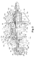
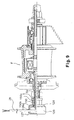
- FIG. 2 is a rear partial cross sectional view of the bicycle hub generator 1 in accordance with the first embodiment of the present invention.
- the bicycle hub generator 1 basically constitutes a rear hub provided at a center portion of the rear wheel 107 of the bicycle. Both ends of a hub shaft 5 are fastened to the swing arm 100 at the rear side of the frame 102 with first and second connecting members or nuts 50 and 51, respectively. Both hub flanges 12a and 12b are configured and arranged to have the spokes 99 hooked thereto.
- the bicycle hub generator 1 shown in Figure 2 is mounted to the rear end of the swing arm 100 along with the rear wheel 107 of the bicycle 101.
- the bicycle hub generator 1 basically comprises the hub shaft 5, a hub body 6, a pair of bearings 7 and 8 and an electricity generating mechanism 9.
- the hub shaft 5 is fastened at both ends to the rear end section of the swing arm 100.
- the hub body 6 is arranged around the outside circumference of the hub shaft 5.
- the bearings 7 and 8 are configured and arranged to support the hub body 6 in a freely rotatable manner on the hub shaft 5.
- the electricity generating mechanism 9 is arranged between the hub body 6 and the hub shaft 5 and configured to generate electricity using the relative rotation of the hub body 6 with respect to the hub shaft 5.
- a freewheel 10 is preferably provided on a first lateral side or the right-hand lateral side of the hub body 6 and a brake mounting part 11 is preferably provided on a second lateral side or the left-hand lateral face of the hub body 6, as shown in Figure 2.
- the bicycle hub generator 1 is also provided with a wiring unit 25, a wiring passage 26, and a wiring draw-out part 27.
- the wiring unit 25 is connected to the electricity generating mechanism 9 and configured to be connected to the control devices 108 and 109 and other external devices of the bicycle 101.
- the wiring passage 26 is formed inside the hub shaft 5 and extends from the electricity generating mechanism 9 to a first shaft end or the left-hand shaft end of the hub shaft 5 (i.e., left-hand of the hub shaft 5 as viewed in Figure 2) such that the wiring unit 25 can be drawn out from the left-hand shaft end.
- the wiring draw-out part 27 is mounted by engaging with the nut 50, which is mounted to the left-hand shaft end of the hub shaft 5 to fixedly couple the hub shaft 5 to the swing arm 100.
- the wiring draw-out part 27 is configured and arranged to cover the wiring unit 25 and guide the wiring unit 25 to the outside.
- the electricity generating mechanism 9 is configured to generate electricity when the rear wheel 107 rotates.
- the generated electric power is delivered to the external devices of the bicycle 101 through the wiring unit 25.
- the wiring unit 25 is arranged to extend from the electricity generating mechanism 9 to the left-hand shaft end through the wiring passage 26 formed inside the hub shaft 5. Then the wiring unit 25 is guided to the outside by the wiring draw-out part 27.
- the wiring draw-out part 27 is mounted by engaging with the first connecting member or the nut 50, which is screwed onto the left-hand shaft end to fasten the hub shaft 5 to the swing arm 100.
- the portion of the wiring unit 25 that is drawn through the wiring passage 26 and out from the first shaft end is protected because the wiring unit 25 is guided to the outside by the wiring draw-out part 27. Since the wiring draw-out part 27 is mounted by engaging with the nut 50, there is no need for a special mounting structure. Thus, the structure of the wiring draw-out part 27 can remain simple.
- the hub shaft 5 is a cylindrical member made of, for example, chromium-molybdenum steel. Both ends of the hub shaft 5 are fastened to the swing arm 100 with the nuts 50 and 51.
- the nut 50 is preferably a conventional hexagonal nut and the nut 51 is preferably a cap nut configured to cover a second shaft end or the right-hand shaft end of the hub shaft 5 as seen in Figure 2.
- the hub shaft 5 preferably includes a large diameter section 5e where the electricity generating mechanism 9 is mounted.
- the hub shaft 5 preferably includes four externally threaded sections 5a, 5b, 5c and 5d arranged on the radially outward facing surface of the hub shaft 5 in succession from the left-hand end to right-hand end as seen in Figure 2.
- the externally threaded section 5a is configured and arranged to threadedly engage with a ball pushing part 14b (discussed later) of the bearing 7, a lock nut 14d for preventing rotation of the ball pushing part 14b, and the nut 50 for fastening the hub shaft 5 to the swing arm 100.
- the external threaded sections 5b and 5c are formed on both ends of the large diameter section 5e and are used to pinch-secure an internal stator unit 17 (discussed later) of the electricity generating mechanism 9.
- the externally threaded section 5d is configured and arranged to threadedly engage with a ball pushing part 15b (discussed later) of the bearing 8, a lock nut 15d for preventing rotation of the ball pushing part 15b, and the nut 51 for fastening the hub shaft 5 to the swing arm 100.
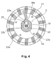
- Each of the externally threaded sections 5b and 5c of the large diameter section 5e of the hub shaft 5 is preferably provided with a pair of mutually parallel flat sections 5f as shown in Figure 4.
- the wiring passage 26 is formed in the radial center portion of the hub shaft 5.
- the hub shaft 5 is provided with a passage hole 26a that communicates radially to the wiring passage 26 in the section where the electricity generating mechanism 9 is mounted on the hub shaft 5.
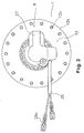
- the wiring unit 25 is guided from the electricity generating mechanism 9 to the wiring passage 26 through the passage hole 26a. Then the wiring unit 25 extends through the wiring passage 26 and is drawn to the outside from the wiring draw-out part 27. Crimping or solderless terminals 25a, for example, are preferably attached to the tip ends of the wiring unit 25 as seen in Figure 3.
- the hub body 6 is preferably made of, for example, a light aluminum alloy and includes a cylindrical case main body 12 and a lid member 13.
- the case main body 12 has an opening 12f provided in a first lateral side or the right-hand lateral face of the case main body 12 (i.e., right-hand side when viewed as shown in Figure 2).
- the lid member 13 is mounted to the case main body 12 in a freely detachable manner and configured to cover the opening 12f of the case main body 12.
- a pair of hub flanges 12a and 12b are arranged on the radially outward facing surface of the case main body 12 in such a manner as to be spaced apart in the axial direction.
- the opening 12f in the case main body 12 is configured and arranged to be large enough to allow the electricity generating mechanism 9 to be installed and an internally threaded section 12g is provided in the opening 12f for mounting the lid member 13.
- the brake mounting part 11 is provided on the left-hand end face (i.e., left-hand when viewed as shown in Figure 2) of the case main body 12.
- a covering 19a preferably made of, for example, metal or resin is mounted in a detachable manner to the internal circumferential surface of the left-hand end of the case main body 12 in order to cover the gap between the case main body 12 and the hub shaft 5.
- the pair of hub flanges 12a and 12b are provided with, for example, sixteen spoke hooking holes 12d and 12e, respectively, that are arranged with equal spacing in the circumferential direction.
- the spoke hooking holes 12d of the hub flange 12a are preferably arranged offset relative to the spoke hooking holes 12e of the hub flange 12b by a distance of one-half of the pitch in the circumferential direction.
- the left-hand end face (i.e., left-hand as shown in Figure 2) of the case main body 12 is also provided with a mounting recessed section 12h having serrations on the radially inward facing surface thereof for preventing rotation of the brake mounting part 11.
- the left-hand end face of the case main body 12 is also provided with a press fitting hole 12i into which the brake mounting part 11 is press fitted such that the brake mounting part 11 fits tightly against the radially inward facing surface of the fitting hole 12i.
- a hub brake such as a disk brake or a roller brake, configured to brake the hub directly (not the rim) can be mounted to the hub body 6.
- electric components can be easily equipped on a comparatively high-performance bicycle.
- the lid member 13 of the hub body 6 is preferably an integral unit that basically includes an outer cylindrical section 13a, an inner cylindrical section 13b, and a connecting section 13c.
- the radially outward facing surface of the outer cylindrical section 13a is provided with an externally threaded section 13d configured to be screwed into the internally threaded section 12g of the case main body 12.
- the inner cylindrical section 13b is arranged radially inward of the outer cylindrical section 13a such that a space exists between the outer cylindrical section 13a and the inner cylindrical section 13b.
- the connecting section 13c is configured and arranged to connect the two cylindrical sections 13a and 13b.
- a connecting bolt 44 for connecting the freewheel 10 is screwed into the radially inward facing surface of the inner cylindrical section 13b.
- the bearing 7 is installed between the case main body 12 and the hub shaft 5.
- the bearing 7 includes a ball bearing part 14a provided on the internal surface of the left end of the brake mounting part 11, the ball pushing part 14b configured to be screwed onto the externally threaded section 5a of the hub shaft 5b, and balls 14c configured to roll while in contact with both the ball pushing part 14b and the ball bearing part 14a.
- the bearing 8 is arranged between the freewheel 10 and the hub shaft 5.
- the bearing 8 includes a ball bearing part 15a provided on the freewheel 10, a ball pushing part 15b configured to be screwed onto the externally threaded section 5d of the hub shaft 5, and balls 15c configured to roll while in contact with both the ball pushing part 15b and the ball bearing part 15a.
- the areas surrounding the balls 14c and 15c are preferably filled with grease.
- the electricity generating mechanism 9 is configured and arranged to use a claw-pole structure having a permanent magnet 16 fixed to the case main body 12 and the internal stator unit 17 fixed to the hub shaft 5.
- the permanent magnet 16 is fixed to the internal surface of the case main body 12 and comprises four magnet bodies divided at equal intervals in the circumferential direction.
- the permanent magnet 16 is provided with north and south poles arranged alternately with equal spacing such that each faces the outer circumference of a yoke 21 (discussed later).
- the internal stator unit 17 has a ring-shaped coil 20 and the yoke 21 provided in such a manner as to surround the coil 20.
- the coil 20 and yoke 21 are fastened to the hub shaft 5 by a pair of nuts 22a and 22b that screw onto the externally threaded sections 5a and 5b, respectively, formed on the outside of the hub shaft 5.
- the nuts 22a and 22b pinch the coil 20 and the yoke 21 therebetween.
- the coil 20 and yoke 21 are positioned such that they face the permanent magnet 16 with respect to the axial direction.
- washers 23a and 23b are installed on the sides of the nuts 22a and 22b that face the yoke 21, respectively.
- the washer 23a has an engaging hole 23c that is generally oval in shape and has a pair of mutually parallel faces that mate with the flat sections 5f of the hub shaft 5.
- the washer 23a engages in a non-rotatable manner with the hub shaft 5.
- the washer 23a is also provided with a protrusion 23d that protrudes toward the yoke 21 and is configured to engage with the yoke 21 as seen in Figure 4.
- the protrusion 23d is preferably formed on the washer 23a by press forming.
- the washer 23a is also provided with a slit 23e for passing the wiring unit 25 that leads out from the coil 20.
- the slit 23e is preferably formed as a cut-away portion extending radially outward from a position corresponding to the passage hole 26a extending to the wiring passage 26 of the hub shaft 5.
- the washer 23a prevents the internal stator unit 17 from rotating relative to the hub shaft 5
- the wiring unit 25 from the coil 20 can be guided reliably to the wiring passage 26.
- the wiring unit 25 extending through the wiring passage 26 is drawn to the outside of the left-hand end face of the hub shaft 5, and is guided by the wiring draw-out part 27.
- the freewheel 10 includes a base part 41 that is connected in a non-rotatable manner to a radially inner portion of the lateral face of the lid member 13 of the hub body 6.
- the freewheel 10 also includes a gear mounting part 42 that is mounted in a freely rotatable manner to the base part 41, and a one-way clutch 43 arranged between the base part 41 and the gear mounting part 42.
- the base part 41 of the freewheel 10 is connected to the inner cylindrical section 13b with the cylindrical connecting bolt 44 that is screwed into the radially inward facing surface of the inner cylindrical section 13b.
- the head of the connecting bolt engages with the base part 41.
- the inner cylindrical section 13b and the base part 41 are also connected together in a non-rotational manner by a connecting member 45 arranged between the inner cylindrical section 13b and the base part 41 on the outside of the connecting bolt 44. Serrations are provided on the radially outward facing surface of the connecting member 45 and the connecting member 45 is press fitted into the serrations provided on inner cylindrical section 13b.
- the serrations of the press fitted connecting member 45 mesh with serrations provided on the radially inward facing surface of one end of the base part 41.
- the base part 41 is cylindrical in shape and the ball bearing part 15a of the bearing 8 is screwed thereon.
- the ball bearing part 15a also serves as a ball pushing part for the bearing that supports the gear mounting part 42 as shown in Figure 2.
- Claw members 43a that constitute the one-way clutch 43 are installed on the base part 41 in such a manner that they can rise and fall freely.
- the one-way clutch 43 is configured to transmit rotation to the base part 41 only in the direction in which the multiple gear cassette 54 mounted to the gear mounting part 42 is rotated (i.e., the direction in which the pedals are rotated) to make the bicycle travel.
- the one-way clutch 43 is also configured not to transmit the rotation of the rear wheel 107 in the traveling direction to the multiple gear cassette 54.
- the claw members 43a are spring-loaded in the rise-up direction with a spring member 43b.
- the gear mounting part 42 is a cylindrical member and has the multiple gear cassette 54 mounted in a non-rotatable manner to its outside circumference.
- Cover members 19b and 19c preferably made of, for example, metal or resin, are mounted in a detachable manner to the internal circumferential surface of the right-hand end of the gear mounting part 42 in order to cover the gap between the gear mounting part 42 and the hub shaft 5.
- the brake mounting part 11 is preferably a separate entity from the case main body 12 and is fixed to the case main body 12 by press fitting.
- a brake drum 55a of a roller brake 55 is configured to be centered and mounted on the brake mounting part 11.
- the brake mounting part 11 is a step-like cylindrical member having a large-diameter radially outward facing surface 11a and a small-diameter radially outward facing surface 11b.
- the brake mounting part 11 also serves as the ball bearing part 14a of the bearing 7. Since the brake mounting part 11 functions as part of the bearing 7, the small-diameter radially outward facing surface 11b is press fitted into the press fitting hole 12i of the case main body 1 2 such that it is fixed without any play or looseness.
- Serrations 11c that mesh with the mounting recessed section 12h are formed on the large-diameter radially outward facing surface 11a and serrations 11d that engage with the brake drum 55a in a non-rotational manner are formed on the left-hand end of the large-diameter radially outward facing surface 11 a.
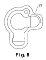
- the wiring draw-out part 27 includes a guide member 28 and a cover member 29.
- the guide member 28 is configured and arranged to engage in a non-rotatable manner with the nut 50 and to guide the wiring unit 25 extending from the left-hand end of the hub shaft 5.
- the cover member 29 is configured and arranged to cover the guide member 28 such that the wiring unit 25 that is guided by the guide member 28 is protected.
- the guide member 28 basically comprises an engaging section 28a, a guiding section 28b, and a fastening section 28c.
- the engaging section 28a is configured and arranged to engage in a non-rotatable manner with the nut 50.
- the guiding section 28b is configured and arranged to guide the wiring unit 25 drawn out from the left-hand end of the hub shaft 5.
- the fastening section 28c is configured and arranged such that the engaging section 28a can be fastened to the nut 50 with a second screw-threaded member or a fastening bolt 30.
- the wiring draw-out part 27 can be fastened in a simple manner by merely turning the fastening bolt 30 such that the fastening bolt 30 moves toward a radially outward facing surface of the nut 50.
- the engaging section 28a preferably has, for example, eighteen 120-degree angular sections 28d such that the engaging section 28a can be mounted to the radially outward facing surfaces of the nut 50 in eighteen different rotational orientations.
- the rotational position of the guiding section 28b can be set close to a prescribed or desired orientation irregardless of the rotational orientation of the nut 50.
- the guide member 28 can be mounted to the radially outward facing surfaces of the first connecting member (the nut 50) at many different rotational orientations. Therefore, the direction in which wiring is drawn out is not greatly affected by variations in the rotational orientation achieved by the nut 50 when the hub shaft 5 is fastened to the swing arm 100 of the frame.
- the guiding section 28b has a groove 28e and at least a portion of the groove 28e is preferably slightly narrower than a width of the wiring unit 25.
- the guiding section 28b also preferably has a plurality of wiring holding parts 28f that are formed in the groove 28e.
- the wiring holding parts 28f are configured and arranged to hold the wiring unit 25. Therefore, the guiding section 28b is configured and arranged to secure the wiring unit 25 in an elastic manner.
- the wiring unit 25 can be held by pressing the wiring unit 25 with the plurality of wiring holding parts 28f and utilizing the elastic quality of the wiring unit 25.
- the wiring unit 25 can be held securely with a simple structure.
- the groove 28e is configured and arranged to bend the wiring unit 25 at approximately 90 degrees from the end of the hub shaft 5 and then bend the wiring unit 25 further such that the wiring unit 25 makes a U-tum from the shaft end. Therefore, the wiring unit 25 can be drawn out from the hub shaft 5 close to the swing arm 100. Moreover, the wiring unit 25 can be protected when the bicycle 101 falls over because the wiring unit 25 is guided in a direction perpendicular to the hub shaft 5.
- the groove 28e is configured and arranged to have a sufficient axial depth to house the wiring unit 25 without the wiring unit 25 protruding to the outside.
- the wiring unit 25 can be housed inside a guide space formed by the groove 28e.
- the portion of the wiring unit 25 that is drawn to the outside from the guide member 28 is arranged so as to follow along the swing arm 100.
- preferably four wiring holding parts 28f are arranged two-each on opposite walls of the groove 28e to be offset from each other at locations that are farther toward the radially outwardly than the portion where the wiring unit 25 bends approximately 90 degrees from the left-hand end of the hub shaft 5.
- a screw-threaded hole 28g for fastening the cover member 29 is provided in a portion of the guide member 28 that faces the cover member 29.
- the fastening section 28c has a screw-threaded portion into which the fastening bolt 30 is inserted, and the guide member 28 is fastened to the nut 50 by pressing against a radially outward facing surface of the nut 50 with the fastening bolt 30.
- the wiring is arranged on the back side of the swing arm 100. Thus, it is difficult to detect the wiring in the external appearance of the bicycle 101 and the external appearance of the bicycle 101 is improved.
- the cover member 29 is fastened to the guide member 28 with a first screw-threaded member or a screw 31 that is screwed into the screw-threaded hole 28g.
- the cover member 29 can be attached and detached easily by using the screw 31.
- the cover member 29 is preferably shaped such that the cover member covers an entire outside surface of the guide member 28 except the portion of the surface of the guide member 28 that faces the swing arm 100. As a result, the wiring unit 25 is protected, and also contaminants can be prevented from entering from the left end of the hub shaft 5.
- the first shaft end is covered by the wiring draw-out part 27 and the second shaft end is protected by the cap nut 51 as seen in Figure 2.
- both ends of the hub shaft 5 are less likely to be damaged and the screw threads on the outside of the hub shaft 5 are also protected from damage.
- the generated electric power is directed out through the wiring draw-out part 27 and delivered to, for example, the control devices 108 and/or 109, as well as the derailleurs, suspensions, and other electric devices equipped with the bicycle 101, through wiring (not shown) that is connected to the solderless terminals 25a of the wiring unit 25. Since the hub generator 1 is provided on the rear wheel 107 in the present embodiment, the distance over which the electric power is delivered to electric components mounted on the rear part of the bicycle 101 other than a lamp of the bicycle 101 is short and the electric power can be delivered with good efficiency. Since the wiring unit 25 is drawn out from the left end of the hub shaft 5, the wiring unit 25 does not become intermingled with the wiring and cables connected to the rear derailleur.
- the wiring unit 25 can be prevented from tangled or can be routed in a less complex manner because the wiring unit 25 is drawn out on the opposite side as the side where the multiple-gear cassette is located, i.e., the side where a rear derailleur or other externally mounted gear changing device is used.
- the portion of the wiring unit 25 that is drawn through the wiring passage 26 and out from the left end of the hub shaft 5 is protected because the wiring unit 25 is covered and guided to the outside by the wiring draw-out part 27.
- the wiring unit 25 is reliably protected because the guide member 28 is covered by the cover member 29 and the wiring draw-out part 27 can be securely fastened to the connecting member, i.e., the nut 50. Moreover, since the wiring draw-out part 27 is mounted by engaging with the nut 50, there is no need for a special mounting structure, and thus, the structure of the wiring draw-out part 27 remains simple.
- a bicycle hub generator 1' in accordance with a second embodiment will now be explained.
- the parts of the second embodiment that are identical to the parts of the first embodiment will be given the same reference numerals as the parts of the first embodiment.
- the descriptions of the parts of the second embodiment that are identical to the parts of the first embodiment may be omitted for the sake of brevity.
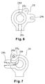
- the bicycle hub generator 1' of the second embodiment is basically identical to the bicycle hub generator 1 of the first embodiment except the wiring draw-out part 127 and a nut 150 are substituted for the wiring draw-out part 27 and the nut 50 of the first embodiment. More specifically, the wiring draw-out part 127 of the second embodiment is configured and arranged to be rotatably mounted to the nut 150 as shown in Figure 9, while the wiring draw-out part 27 of the first embodiment is mounted to the nut 50 in a non-rotatable manner.
- the nut 150 preferably has a nut main body 150a that screws onto the externally threaded section 5a of the hub shaft 5 and a rotatably engaging part 150b that is formed integrally with a top or left end surface (with respect to Figure 9) of nut main body 150a.
- the wiring draw-out part 127 basically comprises a guide member 128 and a cover member 129.
- the guide member 128 is configured to rotatably mount to the nut 150 by elastically engaging with the rotatably engaging part 150a.
- the cover member 129 is configured to cover the guide member 128 such that the wiring unit 25 drawn out from the hub shaft 5 is protected.
- the guide member 128 includes a guide groove 128a formed in an outer circumferential portion of the guide member 128 for guiding the wiring unit 25 in a radial outward direction of the hub shaft 5.
- the wiring draw-out part 127 of the second embodiment is configured and arranged to guide the wiring unit 25 such that the wiring unit 25 is guided from the left-hand end of the hub shaft 5 in a radial direction with respect to the hub shaft 5.
- the wiring unit 25 can be drawn out in a prescribed direction, e.g., toward the portion where the guide groove 128a is formed, irregardless of the rotational orientation of the nut 150 when the hub shaft 5 is fastened to the swing arm 100.
- the wiring unit 25 can be made to follow along the swing arm 100 of the frame no matter what the shape of the frame is.
- the bicycle hub generator 1 or 1' is provided in the rear wheel 107 of the bicycle 101.
- the bicycle hub generator 1 or 1' of the present invention can also be installed in the front wheel 106 of the bicycle 101.
- the wiring draw-out part 27 or 127 is provided on the left-hand end of the hub shaft 5 when the hub shaft 5 is viewed from the rear of the bicycle 101.
- the wiring draw-out part 27 or 127 can also be provide on the right end of the hub shaft 5.
Landscapes
- Engineering & Computer Science (AREA)
- Mechanical Engineering (AREA)
- Connection Of Motors, Electrical Generators, Mechanical Devices, And The Like (AREA)
- Windings For Motors And Generators (AREA)
- Insulation, Fastening Of Motor, Generator Windings (AREA)
- Iron Core Of Rotating Electric Machines (AREA)
- Axle Suspensions And Sidecars For Cycles (AREA)
- Motorcycle And Bicycle Frame (AREA)
Applications Claiming Priority (2)
| Application Number | Priority Date | Filing Date | Title |
|---|---|---|---|
| JP2003306907 | 2003-08-29 | ||
| JP2003306907A JP2005075106A (ja) | 2003-08-29 | 2003-08-29 | 自転車用ハブダイナモ |
Publications (2)
| Publication Number | Publication Date |
|---|---|
| EP1510448A1 true EP1510448A1 (de) | 2005-03-02 |
| EP1510448B1 EP1510448B1 (de) | 2006-05-31 |
Family
ID=34101248
Family Applications (1)
| Application Number | Title | Priority Date | Filing Date |
|---|---|---|---|
| EP04020398A Expired - Lifetime EP1510448B1 (de) | 2003-08-29 | 2004-08-27 | Nabenlichtmaschine für Fahrrad |
Country Status (7)
| Country | Link |
|---|---|
| US (1) | US6924569B2 (de) |
| EP (1) | EP1510448B1 (de) |
| JP (1) | JP2005075106A (de) |
| CN (1) | CN1590201A (de) |
| AT (1) | ATE327937T1 (de) |
| DE (1) | DE602004001028D1 (de) |
| TW (1) | TWI239309B (de) |
Cited By (4)
| Publication number | Priority date | Publication date | Assignee | Title |
|---|---|---|---|---|
| EP1736399A1 (de) * | 2005-06-20 | 2006-12-27 | Shimano Inc. | Von der Fahrgeschwindigkeit abhängige Lichtmaschine für ein Fahrrad |
| EP1733957A3 (de) * | 2005-06-17 | 2007-12-12 | Shimano Inc. | Montageadapter für Rollenbremse |
| EP1980482A1 (de) * | 2007-04-12 | 2008-10-15 | Shimano Inc. | Nabenbremsenmontageadapter |
| US7540361B2 (en) | 2005-06-17 | 2009-06-02 | Shimano Inc. | Roller brake mounting adapter |
Families Citing this family (37)
| Publication number | Priority date | Publication date | Assignee | Title |
|---|---|---|---|---|
| JP4073893B2 (ja) * | 2004-05-13 | 2008-04-09 | 株式会社シマノ | 自転車用内装変速ハブ |
| US20060063624A1 (en) * | 2004-09-20 | 2006-03-23 | Darrell Voss | Transmission systems and methods |
| WO2006124805A2 (en) * | 2005-05-16 | 2006-11-23 | Keith Rutledge | Energy conversion system for hydrogen generation and uses thereof |
| AU2006264181B2 (en) * | 2005-06-29 | 2011-01-27 | Eocycle Technologies Inc. | Transverse flux electrical machine with segmented core stator |
| JP4326553B2 (ja) * | 2006-10-30 | 2009-09-09 | 株式会社シマノ | 自転車用発電装置 |
| JP2008141893A (ja) * | 2006-12-04 | 2008-06-19 | Shimano Inc | 人力駆動車用発電機構のコイル組立体及び人力駆動車用発電ハブ |
| TWM348740U (en) * | 2008-08-29 | 2009-01-11 | Wei-Ting Lin | Driving structure for electric vehicle |
| EP2342803A2 (de) * | 2008-11-03 | 2011-07-13 | Motor Excellence, LLC | Rotorentwürfe für ein quer- oder mischflusssystem |
| US20100282534A1 (en) * | 2009-05-07 | 2010-11-11 | Wei-Ting Lin | Motorized Bicycle with Electric Generating Function |
| JP5474409B2 (ja) * | 2009-06-01 | 2014-04-16 | 株式会社シマノ | 発電ハブ |
| TWI435979B (zh) * | 2009-09-30 | 2014-05-01 | 財團法人工業技術研究院 | 擺動裝置及其轉動狀態偵測裝置與訊息顯示裝置 |
| US20110109206A1 (en) * | 2009-11-09 | 2011-05-12 | Johnson Li | Bicycle power generator |
| WO2011115632A1 (en) | 2010-03-15 | 2011-09-22 | Motor Excellence Llc | Transverse and/or commutated flux systems configured to provide reduced flux leakage, hysteresis loss reduction, and phase matching |
| WO2011115633A1 (en) * | 2010-03-15 | 2011-09-22 | Motor Excellence Llc | Transverse and/or commutated flux system for electric bicycles |
| WO2011115634A1 (en) | 2010-03-15 | 2011-09-22 | Motor Excellence Llc | Transverse and/or commutated flux systems having phase offset |
| US8952590B2 (en) | 2010-11-17 | 2015-02-10 | Electric Torque Machines Inc | Transverse and/or commutated flux systems having laminated and powdered metal portions |
| US8854171B2 (en) | 2010-11-17 | 2014-10-07 | Electric Torque Machines Inc. | Transverse and/or commutated flux system coil concepts |
| CN103477538A (zh) | 2010-11-17 | 2013-12-25 | 电动转矩机器公司 | 具有分段定子层压件的横向和/或换向磁通系统 |
| JP5692588B2 (ja) * | 2010-12-28 | 2015-04-01 | 株式会社デンソー | 駆動装置 |
| JP5692575B2 (ja) | 2010-12-28 | 2015-04-01 | 株式会社デンソー | 駆動装置 |
| JP2013047079A (ja) | 2011-08-29 | 2013-03-07 | Shimano Inc | 自転車用リアハブ |
| JP5607003B2 (ja) | 2011-08-29 | 2014-10-15 | 株式会社シマノ | 自転車用センサの制御装置、自転車用センサの制御方法 |
| JP2013047078A (ja) | 2011-08-29 | 2013-03-07 | Shimano Inc | 自転車用リアハブ |
| US9428246B2 (en) * | 2011-12-09 | 2016-08-30 | Shimano Inc. | Bicycle generator and/or shifting device |
| US8825279B2 (en) | 2012-09-11 | 2014-09-02 | Shimano Inc. | Bicycle power sensing apparatus |
| DE202013102672U1 (de) * | 2013-06-20 | 2014-09-23 | Hightec Edv-Systeme Gmbh | Kabelanschluss für eine Motorbaueinheit eines elektrischen Fahrradhilfsantriebs |
| US9315071B2 (en) | 2013-07-12 | 2016-04-19 | Slipstream Bicycles, Llc | Bicycle wheel system |
| JP6445350B2 (ja) * | 2015-02-25 | 2018-12-26 | 株式会社シマノ | 自転車用発電機 |
| JP6846298B2 (ja) * | 2017-06-20 | 2021-03-24 | 株式会社シマノ | 自転車用ハブユニット |
| JP7199219B2 (ja) * | 2018-12-27 | 2023-01-05 | 株式会社シマノ | ハブ |
| US12103633B2 (en) * | 2021-08-03 | 2024-10-01 | Shimano Inc. | Hub-assembly for human-powered vehicle |
| US11813891B2 (en) | 2021-06-02 | 2023-11-14 | Shimano Inc. | Hub for human-powered vehicle |
| US12304583B2 (en) * | 2021-06-28 | 2025-05-20 | Shimano Inc. | Electrical assembly for human-powered vehicle |
| CN117203120B (zh) * | 2021-04-28 | 2026-03-20 | 尼得科株式会社 | 轮毂及电动车辆 |
| JP2024078867A (ja) * | 2022-11-30 | 2024-06-11 | 株式会社シマノ | 人力駆動車用のハブアセンブリ |
| JP2024078864A (ja) * | 2022-11-30 | 2024-06-11 | 株式会社シマノ | 人力駆動車用のハブアセンブリ |
| TWI858450B (zh) * | 2022-06-20 | 2024-10-11 | 久鼎金屬實業股份有限公司 | 可與自行車車架裝卸的電連接器與具有電連接器的自行車芯軸組件 |
Citations (2)
| Publication number | Priority date | Publication date | Assignee | Title |
|---|---|---|---|---|
| EP0528347A1 (de) * | 1991-08-20 | 1993-02-24 | Vereinigte Drahtwerke AG | Radnabendynamo |
| EP1394030A1 (de) * | 2002-08-26 | 2004-03-03 | Shimano Inc. | Radnabendynamo mit einem Freilauf |
Family Cites Families (10)
| Publication number | Priority date | Publication date | Assignee | Title |
|---|---|---|---|---|
| JPS48103805U (de) | 1972-03-08 | 1973-12-04 | ||
| US5115159A (en) * | 1989-10-25 | 1992-05-19 | Bridgestone Cycle Co., Ltd. | Built-in generator for bicycle |
| US5272938A (en) * | 1992-12-04 | 1993-12-28 | Hsu Chi Hsueh | Flat rim type motor drive mechanism for bicycles |
| US5450915A (en) * | 1993-12-20 | 1995-09-19 | Li; I-Ho | Electric motor-in-wheel |
| US5581136A (en) * | 1994-12-20 | 1996-12-03 | Li; I-Ho | Auxiliary magnetic motor (AMM) |
| JP3556001B2 (ja) * | 1995-01-18 | 2004-08-18 | 株式会社シマノ | 自転車用発電機内装ハブおよび自転車用照明装置 |
| CN1265072A (zh) * | 1997-06-06 | 2000-08-30 | 迈克尔·库特 | 用于靠肌肉力量驱动的带辅助电动机的车用复合驱动装置 |
| US6100615A (en) * | 1998-05-11 | 2000-08-08 | Birkestrand; Orville J. | Modular motorized electric wheel hub assembly for bicycles and the like |
| US6605884B2 (en) * | 2001-06-07 | 2003-08-12 | Shimano, Inc. | Bicycle hub axle having a dynamo thereon |
| JP3740092B2 (ja) * | 2002-06-11 | 2006-01-25 | 株式会社シマノ | 自転車用ハブブレーキ装置 |
-
2003
- 2003-08-29 JP JP2003306907A patent/JP2005075106A/ja active Pending
-
2004
- 2004-02-24 TW TW093104620A patent/TWI239309B/zh not_active IP Right Cessation
- 2004-07-06 US US10/883,991 patent/US6924569B2/en not_active Expired - Lifetime
- 2004-08-27 EP EP04020398A patent/EP1510448B1/de not_active Expired - Lifetime
- 2004-08-27 AT AT04020398T patent/ATE327937T1/de not_active IP Right Cessation
- 2004-08-27 DE DE602004001028T patent/DE602004001028D1/de not_active Expired - Lifetime
- 2004-08-27 CN CNA2004100682562A patent/CN1590201A/zh active Pending
Patent Citations (2)
| Publication number | Priority date | Publication date | Assignee | Title |
|---|---|---|---|---|
| EP0528347A1 (de) * | 1991-08-20 | 1993-02-24 | Vereinigte Drahtwerke AG | Radnabendynamo |
| EP1394030A1 (de) * | 2002-08-26 | 2004-03-03 | Shimano Inc. | Radnabendynamo mit einem Freilauf |
Cited By (5)
| Publication number | Priority date | Publication date | Assignee | Title |
|---|---|---|---|---|
| EP1733957A3 (de) * | 2005-06-17 | 2007-12-12 | Shimano Inc. | Montageadapter für Rollenbremse |
| US7540361B2 (en) | 2005-06-17 | 2009-06-02 | Shimano Inc. | Roller brake mounting adapter |
| EP1736399A1 (de) * | 2005-06-20 | 2006-12-27 | Shimano Inc. | Von der Fahrgeschwindigkeit abhängige Lichtmaschine für ein Fahrrad |
| US7479079B2 (en) | 2005-06-20 | 2009-01-20 | Shimano, Inc. | Variable speed generator for a human powered vehicle |
| EP1980482A1 (de) * | 2007-04-12 | 2008-10-15 | Shimano Inc. | Nabenbremsenmontageadapter |
Also Published As
| Publication number | Publication date |
|---|---|
| CN1590201A (zh) | 2005-03-09 |
| EP1510448B1 (de) | 2006-05-31 |
| TWI239309B (en) | 2005-09-11 |
| DE602004001028D1 (de) | 2006-07-06 |
| US20050029879A1 (en) | 2005-02-10 |
| ATE327937T1 (de) | 2006-06-15 |
| JP2005075106A (ja) | 2005-03-24 |
| TW200508078A (en) | 2005-03-01 |
| US6924569B2 (en) | 2005-08-02 |
Similar Documents
| Publication | Publication Date | Title |
|---|---|---|
| EP1510448B1 (de) | Nabenlichtmaschine für Fahrrad | |
| JP3696189B2 (ja) | 自転車用ハブダイナモ | |
| US8405263B2 (en) | Bicycle generator hub | |
| US6559564B1 (en) | Bicycle hub with generator and antilock functions | |
| US10787032B2 (en) | Bicycle hub | |
| US7338059B2 (en) | Bicycle drive unit | |
| EP1612130A1 (de) | Fahrradnabengenerator | |
| EP2377749B1 (de) | Adapter für einen Nabengenerator | |
| US7059989B2 (en) | Bottom bracket structure with dynamo | |
| JP7430110B2 (ja) | 駆動ユニットおよび電動補助車両 | |
| CN114670972A (zh) | 用于人力车辆的花鼓组件 | |
| JP5300830B2 (ja) | モータ内蔵自転車用ハブ | |
| US11813891B2 (en) | Hub for human-powered vehicle | |
| TWI918784B (zh) | 用於人力車輛的發電機及輪轂總成 | |
| KR200286686Y1 (ko) | 휠용 자가발전 발광장치 | |
| TWI918787B (zh) | 用於人力車輛的輪轂總成及使用於該輪轂總成的電阻件 | |
| CN213676978U (zh) | 单车 | |
| CN206628968U (zh) | 一种自行车发电结构 | |
| JP3668068B2 (ja) | 自転車用ハブダイナモ | |
| TW202229105A (zh) | 用於人力車輛之輪轂 | |
| CN114684317A (zh) | 用于人力车辆的电组件 | |
| TW202313370A (zh) | 用於人力車輛之組件總成 | |
| CN116766825A (zh) | 用于人力车辆的电气部件 | |
| WO2026004496A1 (ja) | モータユニット及び電動自転車 | |
| CN114683766A (zh) | 用于人力车辆的轮毂 |
Legal Events
| Date | Code | Title | Description |
|---|---|---|---|
| PUAI | Public reference made under article 153(3) epc to a published international application that has entered the european phase |
Free format text: ORIGINAL CODE: 0009012 |
|
| AK | Designated contracting states |
Kind code of ref document: A1 Designated state(s): AT BE BG CH CY CZ DE DK EE ES FI FR GB GR HU IE IT LI LU MC NL PL PT RO SE SI SK TR |
|
| AX | Request for extension of the european patent |
Extension state: AL HR LT LV MK |
|
| 17P | Request for examination filed |
Effective date: 20050111 |
|
| 17Q | First examination report despatched |
Effective date: 20050506 |
|
| AKX | Designation fees paid |
Designated state(s): AT BE BG CH CY CZ DE DK EE ES FI FR GB GR HU IE IT LI LU MC NL PL PT RO SE SI SK TR |
|
| GRAP | Despatch of communication of intention to grant a patent |
Free format text: ORIGINAL CODE: EPIDOSNIGR1 |
|
| GRAS | Grant fee paid |
Free format text: ORIGINAL CODE: EPIDOSNIGR3 |
|
| GRAA | (expected) grant |
Free format text: ORIGINAL CODE: 0009210 |
|
| AK | Designated contracting states |
Kind code of ref document: B1 Designated state(s): AT BE BG CH CY CZ DE DK EE ES FI FR GB GR HU IE IT LI LU MC NL PL PT RO SE SI SK TR |
|
| PG25 | Lapsed in a contracting state [announced via postgrant information from national office to epo] |
Ref country code: CZ Free format text: LAPSE BECAUSE OF FAILURE TO SUBMIT A TRANSLATION OF THE DESCRIPTION OR TO PAY THE FEE WITHIN THE PRESCRIBED TIME-LIMIT Effective date: 20060531 Ref country code: IT Free format text: LAPSE BECAUSE OF FAILURE TO SUBMIT A TRANSLATION OF THE DESCRIPTION OR TO PAY THE FEE WITHIN THE PRESCRIBED TIME-LIMIT;WARNING: LAPSES OF ITALIAN PATENTS WITH EFFECTIVE DATE BEFORE 2007 MAY HAVE OCCURRED AT ANY TIME BEFORE 2007. THE CORRECT EFFECTIVE DATE MAY BE DIFFERENT FROM THE ONE RECORDED. Effective date: 20060531 Ref country code: BE Free format text: LAPSE BECAUSE OF FAILURE TO SUBMIT A TRANSLATION OF THE DESCRIPTION OR TO PAY THE FEE WITHIN THE PRESCRIBED TIME-LIMIT Effective date: 20060531 Ref country code: AT Free format text: LAPSE BECAUSE OF FAILURE TO SUBMIT A TRANSLATION OF THE DESCRIPTION OR TO PAY THE FEE WITHIN THE PRESCRIBED TIME-LIMIT Effective date: 20060531 Ref country code: CH Free format text: LAPSE BECAUSE OF FAILURE TO SUBMIT A TRANSLATION OF THE DESCRIPTION OR TO PAY THE FEE WITHIN THE PRESCRIBED TIME-LIMIT Effective date: 20060531 Ref country code: NL Free format text: LAPSE BECAUSE OF FAILURE TO SUBMIT A TRANSLATION OF THE DESCRIPTION OR TO PAY THE FEE WITHIN THE PRESCRIBED TIME-LIMIT Effective date: 20060531 Ref country code: LI Free format text: LAPSE BECAUSE OF FAILURE TO SUBMIT A TRANSLATION OF THE DESCRIPTION OR TO PAY THE FEE WITHIN THE PRESCRIBED TIME-LIMIT Effective date: 20060531 Ref country code: SK Free format text: LAPSE BECAUSE OF FAILURE TO SUBMIT A TRANSLATION OF THE DESCRIPTION OR TO PAY THE FEE WITHIN THE PRESCRIBED TIME-LIMIT Effective date: 20060531 Ref country code: RO Free format text: LAPSE BECAUSE OF FAILURE TO SUBMIT A TRANSLATION OF THE DESCRIPTION OR TO PAY THE FEE WITHIN THE PRESCRIBED TIME-LIMIT Effective date: 20060531 Ref country code: SI Free format text: LAPSE BECAUSE OF FAILURE TO SUBMIT A TRANSLATION OF THE DESCRIPTION OR TO PAY THE FEE WITHIN THE PRESCRIBED TIME-LIMIT Effective date: 20060531 Ref country code: PL Free format text: LAPSE BECAUSE OF FAILURE TO SUBMIT A TRANSLATION OF THE DESCRIPTION OR TO PAY THE FEE WITHIN THE PRESCRIBED TIME-LIMIT Effective date: 20060531 Ref country code: FI Free format text: LAPSE BECAUSE OF FAILURE TO SUBMIT A TRANSLATION OF THE DESCRIPTION OR TO PAY THE FEE WITHIN THE PRESCRIBED TIME-LIMIT Effective date: 20060531 |
|
| REG | Reference to a national code |
Ref country code: GB Ref legal event code: FG4D Ref country code: CH Ref legal event code: EP |
|
| REG | Reference to a national code |
Ref country code: IE Ref legal event code: FG4D |
|
| REF | Corresponds to: |
Ref document number: 602004001028 Country of ref document: DE Date of ref document: 20060706 Kind code of ref document: P |
|
| RAP2 | Party data changed (patent owner data changed or rights of a patent transferred) |
Owner name: SHIMANO INC. |
|
| PG25 | Lapsed in a contracting state [announced via postgrant information from national office to epo] |
Ref country code: IE Free format text: LAPSE BECAUSE OF NON-PAYMENT OF DUE FEES Effective date: 20060828 |
|
| PG25 | Lapsed in a contracting state [announced via postgrant information from national office to epo] |
Ref country code: MC Free format text: LAPSE BECAUSE OF NON-PAYMENT OF DUE FEES Effective date: 20060831 Ref country code: SE Free format text: LAPSE BECAUSE OF FAILURE TO SUBMIT A TRANSLATION OF THE DESCRIPTION OR TO PAY THE FEE WITHIN THE PRESCRIBED TIME-LIMIT Effective date: 20060831 Ref country code: DK Free format text: LAPSE BECAUSE OF FAILURE TO SUBMIT A TRANSLATION OF THE DESCRIPTION OR TO PAY THE FEE WITHIN THE PRESCRIBED TIME-LIMIT Effective date: 20060831 |
|
| PG25 | Lapsed in a contracting state [announced via postgrant information from national office to epo] |
Ref country code: DE Free format text: LAPSE BECAUSE OF FAILURE TO SUBMIT A TRANSLATION OF THE DESCRIPTION OR TO PAY THE FEE WITHIN THE PRESCRIBED TIME-LIMIT Effective date: 20060901 |
|
| PG25 | Lapsed in a contracting state [announced via postgrant information from national office to epo] |
Ref country code: ES Free format text: LAPSE BECAUSE OF FAILURE TO SUBMIT A TRANSLATION OF THE DESCRIPTION OR TO PAY THE FEE WITHIN THE PRESCRIBED TIME-LIMIT Effective date: 20060911 |
|
| NLT2 | Nl: modifications (of names), taken from the european patent patent bulletin |
Owner name: SHIMANO INC. Effective date: 20060802 |
|
| PG25 | Lapsed in a contracting state [announced via postgrant information from national office to epo] |
Ref country code: PT Free format text: LAPSE BECAUSE OF FAILURE TO SUBMIT A TRANSLATION OF THE DESCRIPTION OR TO PAY THE FEE WITHIN THE PRESCRIBED TIME-LIMIT Effective date: 20061031 |
|
| NLV1 | Nl: lapsed or annulled due to failure to fulfill the requirements of art. 29p and 29m of the patents act | ||
| REG | Reference to a national code |
Ref country code: CH Ref legal event code: PL |
|
| PLBE | No opposition filed within time limit |
Free format text: ORIGINAL CODE: 0009261 |
|
| STAA | Information on the status of an ep patent application or granted ep patent |
Free format text: STATUS: NO OPPOSITION FILED WITHIN TIME LIMIT |
|
| EN | Fr: translation not filed | ||
| 26N | No opposition filed |
Effective date: 20070301 |
|
| PG25 | Lapsed in a contracting state [announced via postgrant information from national office to epo] |
Ref country code: FR Free format text: LAPSE BECAUSE OF FAILURE TO SUBMIT A TRANSLATION OF THE DESCRIPTION OR TO PAY THE FEE WITHIN THE PRESCRIBED TIME-LIMIT Effective date: 20070309 Ref country code: GR Free format text: LAPSE BECAUSE OF FAILURE TO SUBMIT A TRANSLATION OF THE DESCRIPTION OR TO PAY THE FEE WITHIN THE PRESCRIBED TIME-LIMIT Effective date: 20060901 |
|
| PG25 | Lapsed in a contracting state [announced via postgrant information from national office to epo] |
Ref country code: BG Free format text: LAPSE BECAUSE OF FAILURE TO SUBMIT A TRANSLATION OF THE DESCRIPTION OR TO PAY THE FEE WITHIN THE PRESCRIBED TIME-LIMIT Effective date: 20060831 Ref country code: EE Free format text: LAPSE BECAUSE OF FAILURE TO SUBMIT A TRANSLATION OF THE DESCRIPTION OR TO PAY THE FEE WITHIN THE PRESCRIBED TIME-LIMIT Effective date: 20060531 |
|
| PG25 | Lapsed in a contracting state [announced via postgrant information from national office to epo] |
Ref country code: LU Free format text: LAPSE BECAUSE OF NON-PAYMENT OF DUE FEES Effective date: 20060827 Ref country code: HU Free format text: LAPSE BECAUSE OF FAILURE TO SUBMIT A TRANSLATION OF THE DESCRIPTION OR TO PAY THE FEE WITHIN THE PRESCRIBED TIME-LIMIT Effective date: 20061201 Ref country code: TR Free format text: LAPSE BECAUSE OF FAILURE TO SUBMIT A TRANSLATION OF THE DESCRIPTION OR TO PAY THE FEE WITHIN THE PRESCRIBED TIME-LIMIT Effective date: 20060531 |
|
| PG25 | Lapsed in a contracting state [announced via postgrant information from national office to epo] |
Ref country code: CY Free format text: LAPSE BECAUSE OF FAILURE TO SUBMIT A TRANSLATION OF THE DESCRIPTION OR TO PAY THE FEE WITHIN THE PRESCRIBED TIME-LIMIT Effective date: 20060531 Ref country code: FR Free format text: LAPSE BECAUSE OF FAILURE TO SUBMIT A TRANSLATION OF THE DESCRIPTION OR TO PAY THE FEE WITHIN THE PRESCRIBED TIME-LIMIT Effective date: 20060531 |
|
| GBPC | Gb: european patent ceased through non-payment of renewal fee |
Effective date: 20080827 |
|
| PG25 | Lapsed in a contracting state [announced via postgrant information from national office to epo] |
Ref country code: GB Free format text: LAPSE BECAUSE OF NON-PAYMENT OF DUE FEES Effective date: 20080827 |