EP1510389A2 - Guiding device for movable element of motor vehicle roof and motor vehicle roof with such guiding device - Google Patents
Guiding device for movable element of motor vehicle roof and motor vehicle roof with such guiding device Download PDFInfo
- Publication number
- EP1510389A2 EP1510389A2 EP04020228A EP04020228A EP1510389A2 EP 1510389 A2 EP1510389 A2 EP 1510389A2 EP 04020228 A EP04020228 A EP 04020228A EP 04020228 A EP04020228 A EP 04020228A EP 1510389 A2 EP1510389 A2 EP 1510389A2
- Authority
- EP
- European Patent Office
- Prior art keywords
- guide
- roof
- arrangement according
- vehicle roof
- transverse direction
- Prior art date
- Legal status (The legal status is an assumption and is not a legal conclusion. Google has not performed a legal analysis and makes no representation as to the accuracy of the status listed.)
- Withdrawn
Links
Images

Classifications
-
- B—PERFORMING OPERATIONS; TRANSPORTING
- B60—VEHICLES IN GENERAL
- B60J—WINDOWS, WINDSCREENS, NON-FIXED ROOFS, DOORS, OR SIMILAR DEVICES FOR VEHICLES; REMOVABLE EXTERNAL PROTECTIVE COVERINGS SPECIALLY ADAPTED FOR VEHICLES
- B60J7/00—Non-fixed roofs; Roofs with movable panels, e.g. rotary sunroofs
- B60J7/02—Non-fixed roofs; Roofs with movable panels, e.g. rotary sunroofs of sliding type, e.g. comprising guide shoes
Definitions
- the present invention relates to a guide assembly for an adjustable element a vehicle roof, in particular for the cover of an externally guided sunroof, according to the preamble of claim 1 and a vehicle roof with such Guide assembly.
- a generic guide arrangement is for example in DE 100 33 887 C1 or DE 101 17 322 A1, wherein the guide arrangement there for each so-called outside guided sunroof is.
- an outside sunroof is a in a closed position a roof opening occlusive lid to expose the Roof opening pushed backwards over the fixed roof surface, with the lid on the side is guided in front and behind each in a roof-fixed guide rail.
- a vehicle roof with a sliding sky is known, the so in a roof-mounted guide in the roof longitudinal direction is slidably guided, that on one side the sky is provided a guide insert, the sliding sky in Roof transverse direction of the arranged on this side guide rail to the on the the other side arranged guide rail biased to tolerances of the To compensate for sliding rooflights in roof transverse direction.
- DE 196 01 120 C1 is a sliding block for the guidance of an adjustable Vehicle roof part described, wherein the sliding block both with respect to the upper and lower as well as with respect to the lateral contact surface by means of a hollow chamber structure is elastic.
- a guide assembly for an adjustable To provide element of a vehicle roof in which possibly in the transverse direction to the Guide acting forces on the adjustable element of the guide assembly possible can be collected, in particular to avoid rattling noises. Furthermore, should a vehicle roof can be created with such a guide arrangement.
- the at least one of the two guide portions with an elastic member is provided to the two guide portions in the transverse direction away from each other and to the Guiding track to compensate, component tolerances in the transverse direction can and thereby the possibility of movement of the adjustable element in the Transverse direction is reduced, which in particular also prevents rattling noises can be.
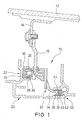
- Fig. 1 is a sectional view in the roof transverse direction, a front guide assembly 10th shown for the cover 12 of an outside sliding roof.
- Such Guide assembly 10 is provided at the front on both sides of the lid.
- the Operation of the outside guided sunroof is known and, for example in DE 100 33 878 C1 or DE 101 17 322 A1.
- the cover 12 is provided on its underside with a cover connection angle 14, which in turn is connected by means of a screw connection with a cover carrier 16.
- the lid carrier 16 carries a sliding cap 18, which in a Karrosseriefesten, in Roof longitudinal direction extending guide rail 20 displaceable in the roof longitudinal direction is guided.
- the portion 22 of the guide rail 20, in which the sliding cap 18 is guided is, forms a lateral contact surface 24 and an upper or lower contact surface 26th or 28.
- the sliding cap 18 is rotatable on a projection 30 of the lid carrier 16 stored.
- the lid support 16 On the lid support 16 is located on the side of a carriage 32, which is a laterally of the Cover carrier 16 has away extending flange 34, via the lateral end of a Sliding cap 36 is inserted. Between the lateral (in Fig. 1 right) end of the flange 34th and the sliding cap 36 is a body 38 of elastic material, preferably rubber, inserted. As can be seen from Fig. 3, the elastic body, for example, a cylindrical or cylindrical shape, wherein the cylinder axis parallel to the Guide rail 20 extends.
- the sliding cap 36 of the carriage 32 is in a portion 40 of the guide rail 20th guided, which has a lateral contact surface 42 and an upper contact surface 44 and a having lower abutment surface 46 for the sliding cap 36.
- the sliding cap 36 of the carriage 32 with respect to the roof upward direction and with respect to the roof transverse direction fixed or guided to the right in Fig. 1, wherein the sliding cap 36 in the portion 42nd the rail 20 is displaceable in the roof longitudinal direction.
- the elastic body 38 serves to the flange 34 and thus the carriage 32 in Roof transverse direction of the lateral contact surface 42 of the portion of the guide rail 20 toward the lid carrier 16 (i.e., to the left in Fig. 1). This way will also the sliding cap 18 of the lid carrier 16 to the lateral contact surface 24 of the portion 22 of the rail 20 (i.e., to the left in Fig. 1).
- the forces acting on it are indicated in Fig. 1 with "F" arrows.
- the sliding cap 36 of the carriage 32 is moved toward the lateral abutment surface 42 (i.e., in FIG Fig. 1 to the right) biased.
- the sliding cap 18 of the lid carrier 16 is independent of Component tolerances always on the left lateral abutment surface 24 of the rail 20, while the sliding cap 36 of the carriage 32 always on the right lateral contact surface 42 of the Rail 20 is applied.
- component tolerances can easily be good be compensated. If, e.g. when driving on a very uneven track, strong in Roof transverse direction acting forces on the cover 12 occur, these may be due to the Elasticity of the body 38 can be easily absorbed, which in particular rattling noises can be avoided.
- the inventive Guiding arrangement instead of an externally guided sunroof basically for others adjustable roof elements can be used, for example, for the lid of a Spoiler roof, a sunroof or a sliding roof.
Abstract
Description
Die vorliegende Erfindung betrifft eine Führungsanordnung für ein verstellbares Element eines Fahrzeugdaches, insbesondere für den Deckel eines außengeführten Schiebedaches, gemäß dem Oberbegriff von Anspruch 1 sowie ein Fahrzeugdach mit einer solchen Führungsanordnung.The present invention relates to a guide assembly for an adjustable element a vehicle roof, in particular for the cover of an externally guided sunroof, according to the preamble of claim 1 and a vehicle roof with such Guide assembly.
Eine gattungsgemäße Führungsanordnung ist beispielsweise in der DE 100 33 887 C1 bzw. der DE 101 17 322 A1 beschrieben, wobei die Führungsanordnung dort jeweils für ein sogenanntes außen geführtes Schiebedach ist. Bei einem außen geführten Schiebedach wird ein in einer Schließstellung eine Dachöffnung verschließender Deckel zum Freilegen der Dachöffnung nach hinten über die feste Dachfläche geschoben, wobei der Deckel seitlich vorn und hinten jeweils in einer dachfesten Führungsschiene geführt ist.A generic guide arrangement is for example in DE 100 33 887 C1 or DE 101 17 322 A1, wherein the guide arrangement there for each so-called outside guided sunroof is. In an outside sunroof is a in a closed position a roof opening occlusive lid to expose the Roof opening pushed backwards over the fixed roof surface, with the lid on the side is guided in front and behind each in a roof-fixed guide rail.
Insbesondere bei großen Deckeln können, z.B. beim Befahren eines stark unebenen Streckenabschnitts, beträchtliche Kräfte in Dachquerrichtung auf den Deckel wirken, was bei einem durch Bauteiltoleranzen bedingten Spiel der Führung des Deckels in Dachquerrichtung zu einer Bewegung des Deckels in Dachquerrichtung und insbesondere zu Klappergeräuschen zwischen der Deckelmechanik und der dachfesten Führung führen kann.Especially with large lids, e.g. when driving a heavily uneven Stretch section, considerable forces in the roof transverse direction on the cover act, what at a conditional by component tolerances game the leadership of the lid in the roof transverse direction to a movement of the lid in the roof transverse direction and in particular to rattling noises between the lid mechanism and the roof-fixed guide can lead.
Aus der DE 41 34 065 C1 ist ein Fahrzeugdach mit einem Schiebehimmel bekannt, der so in einer dachfesten Führung in Dachlängsrichtung verschiebbar geführt ist, dass auf einer Seite des Himmels ein Führungseinsatz vorgesehen ist, der den Schiebehimmel in Dachquerrichtung von der auf dieser Seite angeordneten Führungsschiene zu der auf der anderen Seite angeordneten Führungsschiene hin vorspannt, um Toleranzen des Schiebehimmels in Dachquerrichtung auszugleichen. From DE 41 34 065 C1, a vehicle roof with a sliding sky is known, the so in a roof-mounted guide in the roof longitudinal direction is slidably guided, that on one side the sky is provided a guide insert, the sliding sky in Roof transverse direction of the arranged on this side guide rail to the on the the other side arranged guide rail biased to tolerances of the To compensate for sliding rooflights in roof transverse direction.
In der DE 196 01 120 C1 ist eine Gleitbacke für die Führung eines verstellbaren Fahrzeugdachteils beschrieben, wobei die Gleitbacke sowohl bezüglich der oberen und unteren als auch bezüglich der seitlichen Anlagefläche mittels einer Hohlkammerstruktur elastisch ausgebildet ist.In DE 196 01 120 C1 is a sliding block for the guidance of an adjustable Vehicle roof part described, wherein the sliding block both with respect to the upper and lower as well as with respect to the lateral contact surface by means of a hollow chamber structure is elastic.
Es ist Aufgabe der vorliegenden Erfindung, eine Führungsanordnung für ein verstellbares Element eines Fahrzeugdaches zu schaffen, bei welcher eventuell in Querrichtung zu der Führung wirkende Kräfte auf das verstellbare Element von der Führungsanordnung möglichst aufgefangen werden können, um insbesondere Klappergeräusche zu vermeiden. Ferner soll ein Fahrzeugdach mit einer solchen Führungsanordnung geschaffen werden.It is an object of the present invention, a guide assembly for an adjustable To provide element of a vehicle roof, in which possibly in the transverse direction to the Guide acting forces on the adjustable element of the guide assembly possible can be collected, in particular to avoid rattling noises. Furthermore, should a vehicle roof can be created with such a guide arrangement.
Diese Aufgabe wird erfindungsgemäß gelöst durch eine Führungsanordnung gemäß Anspruch 1 sowie ein Fahrzeugdach gemäß Anspruch 11. Bei dieser Lösung ist vorteilhaft, dass dadurch, das mindestens einer der beiden Führungsabschnitte mit einem elastischen Bauteil versehen ist, um die beiden Führungsabschnitte in Querrichtung voneinander weg und zu der Führungsbahn hin vorzuspannen, Bauteiltoleranzen in der Querrichtung ausgeglichen werden können und dadurch die Bewegungsmöglichkeit des verstellbaren Elements in der Querrichtung reduziert wird, wodurch insbesondere auch Klappergeräusche verhindert werden können.This object is achieved by a guide assembly according to claim 1 and a vehicle roof according to claim 11. In this solution is advantageous that characterized, the at least one of the two guide portions with an elastic member is provided to the two guide portions in the transverse direction away from each other and to the Guiding track to compensate, component tolerances in the transverse direction can and thereby the possibility of movement of the adjustable element in the Transverse direction is reduced, which in particular also prevents rattling noises can be.
Bevorzugte Ausgestaltungen der Erfindungen ergeben sich aus den Unteransprüchen.Preferred embodiments of the invention will become apparent from the dependent claims.
Im folgenden wird die Erfindung anhand der beigefügten Zeichnungen beispielhaft näher erläutert. Dabei zeigen:
- Fig. 1
- eine Querschnittansicht der vorderen Führungsanordnung auf einer Seite eines außen geführten Schiebedaches;
- Fig. 2
- eine perspektivische vergrößerte Ansicht des rechten seitlichen Führungsabschnitts der Führungsanordnung von Fig. 1, wobei jedoch die Führungsschiene weggelassen ist; und
- Fig. 3
- eine Ansicht wie Fig. 2, wobei jedoch die Gleitkappe weggelassen ist.
- Fig. 1
- a cross-sectional view of the front guide assembly on one side of an outside sliding roof;
- Fig. 2
- a perspective enlarged view of the right side guide portion of the guide assembly of Figure 1, but with the guide rail is omitted ..; and
- Fig. 3
- a view like Fig. 2, but with the sliding cap is omitted.
In Fig. 1 ist in einer Schnittansicht in Dachquerrichtung eine vordere Führungsanordnung 10
für den Deckel 12 eines außen geführten Schiebedaches gezeigt. Eine solche
Führungsanordnung 10 ist vorn an beiden Seiten des Deckels vorgesehen. Die
Funktionsweise von außen geführten Schiebedächern ist an sich bekannt und beispielsweise
in der DE 100 33 878 C1 oder der DE 101 17 322 A1 beschrieben.In Fig. 1 is a sectional view in the roof transverse direction, a front guide assembly 10th
shown for the
Der Deckel 12 ist an seiner Unterseite mit einem Deckelanbindungswinkel 14 versehen,
welcher wiederum mittels einer Schraubverbindung mit einem Deckelträger 16 verbunden ist.
Der Deckelträger 16 trägt eine Gleitkappe 18, welche in einer karrosseriefesten, in
Dachlängsrichtung verlaufenden Führungsschiene 20 in Dachlängsrichtung verschiebbar
geführt ist. Der Teilbereich 22 der Führungsschiene 20, in welcher die Gleitkappe 18 geführt
ist, bildet dabei eine seitliche Anlagefläche 24 sowie eine obere bzw. untere Anlagefläche 26
bzw. 28. Die Gleitkappe 18 ist auf einem Vorsprung 30 des Deckelträgers 16 drehbar
gelagert. Mittels der Anlageflächen 26 und 28 wird die Gleitkappe 18 bezüglich der
Dachhochrichtung geführt, während die Anlagefläche 24 zur seitlichen Führung dient.The
An dem Deckelträger 16 liegt seitlich ein Schlitten 32 an, welcher einen sich seitlich von dem
Deckelträger 16 weg erstreckenden Flansch 34 aufweist, über dessen seitliches Ende eine
Gleitkappe 36 gesteckt ist. Zwischen dem seitlichen (in Fig. 1 rechten) Ende des Flanschs 34
und der Gleitkappe 36 ist ein Körper 38 aus elastischem Material, vorzugsweise aus Gummi,
eingelegt. Wie aus Fig. 3 ersichtlich ist, kann der elastische Körper beispielsweise eine
zylindrische oder zylinderartige Form aufweisen, wobei die Zylinderachse parallel zu der
Führungsschiene 20 verläuft.On the
Die Gleitkappe 36 des Schlittens 32 ist in einem Teilbereich 40 der Führungsschiene 20
geführt, welcher eine seitliche Anlagefläche 42 sowie eine obere Anlagefläche 44 und eine
untere Anlagefläche 46 für die Gleitkappe 36 aufweist. Auf diese Weise ist die Gleitkappe 36
des Schlittens 32 bezüglich der Dachhochrichtung sowie bezüglich der Dachquerrichtung
nach rechts in Fig. 1 festgelegt bzw. geführt, wobei die Gleitkappe 36 in dem Teilbereich 42
der Schiene 20 in Dachlängsrichtung verschiebbar ist.The
Der elastische Körper 38 dient dazu, den Flansch 34 und damit den Schlitten 32 in
Dachquerrichtung von der seitlichen Anlagefläche 42 des Teilbereichs der Führungsschiene
20 zum Deckelträger 16 hin (d.h. in Fig. 1 nach links) vorzuspannen. Auf diese Weise wird
auch die Gleitkappe 18 des Deckelträgers 16 zur seitlichen Anlagefläche 24 des Teilbereichs
22 der Schiene 20 (d.h. in Fig. 1 nach links) hin vorgespannt. Die dabei wirkenden Kräfte
sind in Fig. 1 mit mit "F" bezeichneten Pfeilen angedeutet. Die Gleitkappe 36 des Schlittens
32 wird dabei mittels des elastischen Körpers 38 zur seitlichen Anlagefläche 42 hin (d.h. in
Fig. 1 nach rechts) vorgespannt.The
Auf diese Weise liegt die Gleitkappe 18 des Deckelträgers 16 unabhängig von
Bauteiltorelanzen immer an der linken seitlichen Anlagefläche 24 der Schiene 20 an, während
die Gleitkappe 36 des Schlittens 32 immer an der rechten seitlichen Anlagefläche 42 der
Schiene 20 anliegt. Auf diese Weise können Bauteiltoleranzen auf einfache Weise gut
ausgeglichen werden. Falls, z.B. bei Fahrt auf einer sehr unebenen Strecke, starke in
Dachquerrichtung wirkende Kräfte am Deckel 12 auftreten, können diese aufgrund der
Elastizität des Körpers 38 gut aufgefangen werden, wodurch insbesondere Klappergeräusche
vermieden werden können.In this way, the
Anstelle des elastischen Körpers 38 könnte grundsätzlich auch ein anderes federelastisches
Element vorgesehen sein. Ferner versteht es sich, dass die erfindungsgemäße
Führungsanordnung statt für ein außen geführtes Schiebedach grundsätzlich auch für andere
verstellbare Dachelemente verwendet werden kann, beispielsweise für den Deckel eines
Spoilerdaches, eines Schiebedaches oder eines Schiebehebedaches. Instead of the
- 1010
- Führungsanordnungguide assembly
- 1212
- Schiebedeckelsliding cover
- 1414
- DeckelanbindungswinkelCover connection angle
- 1616
- Deckelträgercover carrier
- 1818
- Gleitkappesliding cap
- 2020
- Führungsschieneguide rail
- 2222
- Teilbereich von 20Subarea of 20
- 2424
- seitliche Anlageflächelateral contact surface
- 2626
- obere Anlageflächeupper contact surface
- 2828
- untere Anlageflächelower contact surface
- 3030
- Vorsprunghead Start
- 3232
- Schlittencarriage
- 3434
- Flanschflange
- 3636
- Gleitkappesliding cap
- 3838
- elastischer Körperelastic body
- 4040
- Teilbereich von 20Subarea of 20
- 4242
- seitliche Anlageflächelateral contact surface
- 4444
- obere Anlageflächeupper contact surface
- 4646
- untere Anlageflächelower contact surface
Claims (14)
Applications Claiming Priority (2)
| Application Number | Priority Date | Filing Date | Title |
|---|---|---|---|
| DE2003139264 DE10339264B3 (en) | 2003-08-26 | 2003-08-26 | Guiding arrangement for an adjustable element of a vehicle roof and vehicle roof with such a guide arrangement |
| DE10339264 | 2003-08-26 |
Publications (2)
| Publication Number | Publication Date |
|---|---|
| EP1510389A2 true EP1510389A2 (en) | 2005-03-02 |
| EP1510389A3 EP1510389A3 (en) | 2006-04-12 |
Family
ID=34089198
Family Applications (1)
| Application Number | Title | Priority Date | Filing Date |
|---|---|---|---|
| EP04020228A Withdrawn EP1510389A3 (en) | 2003-08-26 | 2004-08-26 | Guiding device for movable element of motor vehicle roof and motor vehicle roof with such guiding device |
Country Status (2)
| Country | Link |
|---|---|
| EP (1) | EP1510389A3 (en) |
| DE (1) | DE10339264B3 (en) |
Cited By (2)
| Publication number | Priority date | Publication date | Assignee | Title |
|---|---|---|---|---|
| WO2007012297A1 (en) * | 2005-07-27 | 2007-02-01 | Webasto Ag | Mounting arrangement for a vehicle sliding roof moving externally |
| CN103660884A (en) * | 2012-09-25 | 2014-03-26 | 银娜珐天窗系统集团股份有限公司 | Drive mechanism and open roof construction provided therewith |
Families Citing this family (1)
| Publication number | Priority date | Publication date | Assignee | Title |
|---|---|---|---|---|
| DE102006058524B4 (en) * | 2006-12-12 | 2008-11-20 | Webasto Ag | Storage arrangement for a slider in a guide channel of a guide rail |
Citations (4)
| Publication number | Priority date | Publication date | Assignee | Title |
|---|---|---|---|---|
| DE4134065C1 (en) | 1991-10-15 | 1992-10-22 | Webasto Ag Fahrzeugtechnik, 8035 Stockdorf, De | Slide support for car sun roof - has slide guideway with slots along both long sides, coacting with associated guide rails |
| DE19601120C1 (en) | 1996-01-13 | 1997-02-20 | Webasto Karosseriesysteme | Sliding block for guiding roofs of vehicles in longitudinal guides |
| DE10033887C1 (en) | 2000-07-12 | 2001-08-30 | Webasto Vehicle Sys Int Gmbh | Vehicle roof with at least one cover slidable above the fixed vehicle roof |
| DE10117322A1 (en) | 2001-01-11 | 2002-07-25 | Webasto Vehicle Sys Int Gmbh | vehicle roof |
Family Cites Families (2)
| Publication number | Priority date | Publication date | Assignee | Title |
|---|---|---|---|---|
| NL1014953C2 (en) * | 2000-04-14 | 2001-10-16 | Inalfa Ind Bv | Open roof construction for a vehicle. |
| NL1016322C2 (en) * | 2000-10-04 | 2002-04-08 | Inalfa Ind Bv | Open roof construction for a vehicle. |
-
2003
- 2003-08-26 DE DE2003139264 patent/DE10339264B3/en not_active Expired - Fee Related
-
2004
- 2004-08-26 EP EP04020228A patent/EP1510389A3/en not_active Withdrawn
Patent Citations (4)
| Publication number | Priority date | Publication date | Assignee | Title |
|---|---|---|---|---|
| DE4134065C1 (en) | 1991-10-15 | 1992-10-22 | Webasto Ag Fahrzeugtechnik, 8035 Stockdorf, De | Slide support for car sun roof - has slide guideway with slots along both long sides, coacting with associated guide rails |
| DE19601120C1 (en) | 1996-01-13 | 1997-02-20 | Webasto Karosseriesysteme | Sliding block for guiding roofs of vehicles in longitudinal guides |
| DE10033887C1 (en) | 2000-07-12 | 2001-08-30 | Webasto Vehicle Sys Int Gmbh | Vehicle roof with at least one cover slidable above the fixed vehicle roof |
| DE10117322A1 (en) | 2001-01-11 | 2002-07-25 | Webasto Vehicle Sys Int Gmbh | vehicle roof |
Cited By (6)
| Publication number | Priority date | Publication date | Assignee | Title |
|---|---|---|---|---|
| WO2007012297A1 (en) * | 2005-07-27 | 2007-02-01 | Webasto Ag | Mounting arrangement for a vehicle sliding roof moving externally |
| CN103660884A (en) * | 2012-09-25 | 2014-03-26 | 银娜珐天窗系统集团股份有限公司 | Drive mechanism and open roof construction provided therewith |
| EP2711219A1 (en) * | 2012-09-25 | 2014-03-26 | Inalfa Roof Systems Group B.V. | Drive mechanism and open roof construction provided therewith |
| KR20140040016A (en) * | 2012-09-25 | 2014-04-02 | 이날파 루프 시스템즈 그룹 비.브이. | Drive mechanism and open roof construction provided therewith |
| US8991912B2 (en) | 2012-09-25 | 2015-03-31 | Inalfa Roof Systems Group B.V. | Drive mechanism and open roof construction provided therewith |
| CN103660884B (en) * | 2012-09-25 | 2017-10-31 | 英纳法天窗系统集团有限公司 | Drive mechanism and the Open roof construction provided with the drive mechanism |
Also Published As
| Publication number | Publication date |
|---|---|
| DE10339264B3 (en) | 2005-03-24 |
| EP1510389A3 (en) | 2006-04-12 |
Similar Documents
| Publication | Publication Date | Title |
|---|---|---|
| DE2532187A1 (en) | SUNROOF FOR MOTOR VEHICLES | |
| DE3817391C2 (en) | Sliding shoe for vehicle sunroofs | |
| EP1193098B1 (en) | Sealing system for a support lever on an openable vehicle roof | |
| DE3532679C1 (en) | Guide bolts in a sunroof arrangement | |
| EP1389545B1 (en) | Guiding shoe for openable vehicle roofs or covers | |
| DE102010018457B4 (en) | Sliding element of a guide device of an adjustable roof element of an openable vehicle roof | |
| EP1425195B1 (en) | Guide arrangement for a roof element on an opening vehicle roof | |
| DE102007001286B4 (en) | Openable vehicle roof with drive carriage for a roof element | |
| DE10331269A1 (en) | Vehicle roof has cover device with roof lining plate joined to guide elements guided by longitudinal tracks and transversely and longitudinally movable panel covering edge of lining plate | |
| DE602004002027T2 (en) | Window and motor vehicle with the same | |
| EP1389546B1 (en) | Guide channel for sliding shoes of openable vehicle roofs or covers | |
| DE60009784T2 (en) | Construction of an openable vehicle roof | |
| DE10339264B3 (en) | Guiding arrangement for an adjustable element of a vehicle roof and vehicle roof with such a guide arrangement | |
| EP0755815B1 (en) | Foldable roof for vehicle | |
| DE102019124108A1 (en) | Movable guide element for a cable | |
| DE202007001217U1 (en) | Automotive roof has fixed rear panel and front panel that slides through side guides | |
| DE102007008821B4 (en) | vehicle roof | |
| DE102007001287B4 (en) | Sled with glider | |
| DE102006055609B4 (en) | Convertible vehicle roof | |
| DE3425273A1 (en) | Sliding shoe for a sliding roof of a vehicle | |
| DE102007036403B4 (en) | Spoiler device and vehicle | |
| EP2860052B1 (en) | Roof for a motor vehicle | |
| DE102004022012B4 (en) | roof arrangement | |
| EP1396363A1 (en) | Driving mechanism for a sliding roof panel | |
| DE10336618A1 (en) | Drive arrangement for a slidable vehicle roof element comprises a cable connector provided with at least one glide cap which is in gliding contact with a guide rail |
Legal Events
| Date | Code | Title | Description |
|---|---|---|---|
| PUAI | Public reference made under article 153(3) epc to a published international application that has entered the european phase |
Free format text: ORIGINAL CODE: 0009012 |
|
| AK | Designated contracting states |
Kind code of ref document: A2 Designated state(s): AT BE BG CH CY CZ DE DK EE ES FI FR GB GR HU IE IT LI LU MC NL PL PT RO SE SI SK TR |
|
| AX | Request for extension of the european patent |
Extension state: AL HR LT LV MK |
|
| PUAL | Search report despatched |
Free format text: ORIGINAL CODE: 0009013 |
|
| AK | Designated contracting states |
Kind code of ref document: A3 Designated state(s): AT BE BG CH CY CZ DE DK EE ES FI FR GB GR HU IE IT LI LU MC NL PL PT RO SE SI SK TR |
|
| AX | Request for extension of the european patent |
Extension state: AL HR LT LV MK |
|
| 17P | Request for examination filed |
Effective date: 20061011 |
|
| AKX | Designation fees paid |
Designated state(s): AT BE BG CH CY CZ DE DK EE ES FI FR GB GR HU IE IT LI LU MC NL PL PT RO SE SI SK TR |
|
| STAA | Information on the status of an ep patent application or granted ep patent |
Free format text: STATUS: THE APPLICATION IS DEEMED TO BE WITHDRAWN |
|
| 18D | Application deemed to be withdrawn |
Effective date: 20120301 |