EP1510298B1 - Power tool - Google Patents
Power tool Download PDFInfo
- Publication number
- EP1510298B1 EP1510298B1 EP04020454A EP04020454A EP1510298B1 EP 1510298 B1 EP1510298 B1 EP 1510298B1 EP 04020454 A EP04020454 A EP 04020454A EP 04020454 A EP04020454 A EP 04020454A EP 1510298 B1 EP1510298 B1 EP 1510298B1
- Authority
- EP
- European Patent Office
- Prior art keywords
- handle
- power tool
- dynamic vibration
- elastic element
- vibration reducer
- Prior art date
- Legal status (The legal status is an assumption and is not a legal conclusion. Google has not performed a legal analysis and makes no representation as to the accuracy of the status listed.)
- Active
Links
- 239000003638 chemical reducing agent Substances 0.000 claims description 35
- 230000005540 biological transmission Effects 0.000 claims description 3
- 238000005553 drilling Methods 0.000 claims description 3
- 230000005484 gravity Effects 0.000 claims description 3
- 230000033001 locomotion Effects 0.000 description 11
- 238000010276 construction Methods 0.000 description 6
- 238000005520 cutting process Methods 0.000 description 5
- 238000000034 method Methods 0.000 description 2
- 125000004122 cyclic group Chemical group 0.000 description 1
- 238000013016 damping Methods 0.000 description 1
- 230000007423 decrease Effects 0.000 description 1
- 230000000994 depressogenic effect Effects 0.000 description 1
- 238000009413 insulation Methods 0.000 description 1
- 230000000717 retained effect Effects 0.000 description 1
Images
Classifications
-
- B—PERFORMING OPERATIONS; TRANSPORTING
- B23—MACHINE TOOLS; METAL-WORKING NOT OTHERWISE PROVIDED FOR
- B23D—PLANING; SLOTTING; SHEARING; BROACHING; SAWING; FILING; SCRAPING; LIKE OPERATIONS FOR WORKING METAL BY REMOVING MATERIAL, NOT OTHERWISE PROVIDED FOR
- B23D51/00—Sawing machines or sawing devices working with straight blades, characterised only by constructional features of particular parts; Carrying or attaching means for tools, covered by this subclass, which are connected to a carrier at both ends
- B23D51/01—Sawing machines or sawing devices working with straight blades, characterised only by constructional features of particular parts; Carrying or attaching means for tools, covered by this subclass, which are connected to a carrier at both ends characterised by the handle
-
- B—PERFORMING OPERATIONS; TRANSPORTING
- B25—HAND TOOLS; PORTABLE POWER-DRIVEN TOOLS; MANIPULATORS
- B25D—PERCUSSIVE TOOLS
- B25D17/00—Details of, or accessories for, portable power-driven percussive tools
- B25D17/04—Handles; Handle mountings
- B25D17/043—Handles resiliently mounted relative to the hammer housing
-
- B—PERFORMING OPERATIONS; TRANSPORTING
- B25—HAND TOOLS; PORTABLE POWER-DRIVEN TOOLS; MANIPULATORS
- B25D—PERCUSSIVE TOOLS
- B25D2217/00—Details of, or accessories for, portable power-driven percussive tools
- B25D2217/0073—Arrangements for damping of the reaction force
- B25D2217/0076—Arrangements for damping of the reaction force by use of counterweights
- B25D2217/0092—Arrangements for damping of the reaction force by use of counterweights being spring-mounted
-
- B—PERFORMING OPERATIONS; TRANSPORTING
- B25—HAND TOOLS; PORTABLE POWER-DRIVEN TOOLS; MANIPULATORS
- B25D—PERCUSSIVE TOOLS
- B25D2250/00—General details of portable percussive tools; Components used in portable percussive tools
- B25D2250/371—Use of springs
Description
- The present invention relates to a technique of reducing vibration in a handle of a reciprocating power tool which drives a tool bit at a predetermined cycle, such as an electric hammer and a hammer drill.
-
Japanese non-examined utility model publication No. 1-18306 -
DE 100 36 078 A1 andDE 16 720 58 U disclose further examples of power tools with handles connected to the housing via one or more elastic elements. -
US 4 282 938 A discloses a vibration insulation device for a vibratory machine. -
US 5 927 407 A discloses an isolator for use in a hand-held vibrating device. -
GB 2 137 132 A - In particular
DE 100 36 078 A1 andGB 2 137 132 A - With this construction, the elastic element can alleviate vibration caused in the hammer body and inputted to the handle. In the construction in which the handle is connected via the elastic element, the elastic element is required to have a smaller spring constant in order to improve vibration absorbing effectiveness. However, if the spring constant is smaller, the hammer body and the handle may swing with respect to each other. Therefore, the spring constant is practically made large enough to avoid such swinging. In this case, however, the vibration absorbing effectiveness decreases.
- Accordingly, it is an object of the present invention to provide an effective vibration reducing technique in improving vibration absorbing effectiveness of a handle in a reciprocating power tool.
- This object is achieved by a power tool according to claim 1. According to the invention, representative reciprocating power tool includes a power tool body, a handle, an elastic element and a dynamic vibration reducer. The handle is connected to the power tool body via the elastic element. The dynamic vibration reducer is provided in or on the outside of the handle. With such construction, while the elastic element absorbs vibration transmitted from the power tool body to the handle, the dynamic vibration reducer absorbs the vibration which the elastic member can not absorb.
- Other objects, features and advantages of the present invention will be readily understood after reading the following detailed description together with the accompanying drawings and the claims.
-
-
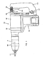
FIG. 1 is a front view showing an entire electric hammer according to a representative embodiment of the invention. -
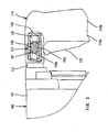
FIG. 2 is a partial section showing the essential section of the representative embodiment. - A representative reciprocating power tool includes a power tool body and a handle which is connected to the power tool body via an elastic element. The "reciprocating power tool" of the present invention may include an impact power tool such as an electric hammer and a hammer drill, which performs a crushing operation or a drilling operation on a workpiece by the axial striking movement or by the axial striking movement and rotation of a tool bit. The power tool may also include a cutting power tool such as a reciprocating saw and a jigsaw, which performs a cutting operation on a workpiece by reciprocating a blade. The "elastic element" may include a spring or rubber. Further, the manner of "connecting the handle to the power tool body via an elastic element" may include a manner of connecting the handle at the both ends to the power tool body (double end supporting) and a manner of connecting the handle at one end to the power tool body (cantilever supporting). Further, in the case of double end supporting, either one or both of the ends may be supported by the elastic element. Basically, when vibration is caused in the power tool body during the operation, transmission of the vibration from the power tool body to the handle can be reduced by the vibration absorbing function of the elastic element.
- Further, according to the invention, the handle is provided with a dynamic vibration reducer. The dynamic vibration reducer may be suitably disposed within the handle or on the outside surface of the handle. Thus, in addition to the elastic element, the dynamic vibration reducer further reduces the vibration which could not be completely absorbed by the elastic element. As a result, vibration reduction with respect to the handle can be ensured.
- The combinations of features and steps disclosed within the following detailed description may not be necessary to practice the invention in the broadest sense, and are instead taught merely to particularly describe some representative examples of the invention, which detailed description will now be given with reference to the accompanying drawings.
- A representative embodiment of the invention will now be described with reference to the drawings. An electric hammer will be explained as a representative example of the power tool according to the embodiment of the present invention.
FIG. 1 shows the entire electric hammer andFIG. 2 shows an essential part thereof. As shown inFIG. 1 , a representativeelectric hammer 101 according to the embodiment mainly includes abody 103 that defines the contours of theelectric hammer 101. Thebody 103 includes amotor housing 105, agear housing 107 and atool holder 109 which occupies the tip end (front end) region of thegear housing 107. Thebody 103 is a feature that corresponds to the "power tool body" according to the invention. A handle (handgrip) 113 is mounted on the rear end of themotor housing 105 and thegear housing 107. - Although it is not particularly shown, an impact driving mechanism is disposed within the
body 103 and serves to transmit a striking movement to ahammer bit 111 which is retained by thetool holder 109. Thehammer bit 111 is a feature that corresponds to the "tool bit" according to the invention. - Because the construction of the impact driving mechanism for the
hammer bit 111 as itself is a well known art, it will be only briefly explained. A driving motor as a driving source is disposed within themotor housing 105. The rotating output of the driving motor is converted into reciprocating movement of a piston via a crank mechanism which is disposed within thegear housing 107. When the piston linearly moves, a striker linearly moves forward at high speed by the action of a so-called air spring and collides with an impact bolt as an intermediate element. The impact bolt, in turn, linearly moves forward at high speed and collides with thehammer bit 111. Then, thehammer bit 111 linearly moves forward at high speed. Thus, thehammer bit 111 performs a hammering (striking) movement and as a result, hammering operation is performed to a workpiece (not particularly shown). - The striker and the impact bolt form a striking mechanism that transmits a striking movement to the
hammer bit 111. The striking mechanism and thehammer bit 111 move linearly generally along the same line. When thehammer bit 111 is driven, vibration is caused within thebody 103 by the striking movement of thehammer bit 111. - In order to reduce transmission of the vibration which has been caused in the
body 103 to thehandle 113, thehandle 113 is connected to thebody 103 in the following manner. Specifically, one end (upper end) of thehandle 113 is connected to the rear end of thegear housing 107 via anelastic element 115 for absorbing vibration. For example, a spring or rubber is used for theelastic element 115. The connection by theelastic element 115 is located rearward of thehammer bit 111 near a travel path P of the center of gravity of the reciprocatinghammer bit 111. Theelastic element 115 applies a biasing force at least in the input direction of vibration or in the longitudinal direction of thehammer bit 111. Further, theelastic element 115 may be configured to apply a biasing force in the other directions as well. - Further, the other end (lower end) of the
handle 113 is connected to the rear end of themotor housing 105 via apivot 117 such that thehandle 113 can rotate around thepivot 117. As a result of such rotation, the upper end region of thehandle 113 moves substantially in the same direction as the input direction Q of vibration inputted into the handle 113 (equal to the longitudinal direction of the hammer bit 111). Thus, the vibration absorbing function of theelastic element 115 is performed with respect to the vibration in the longitudinal direction of thehammer bit 111. - Further, a
dynamic vibration reducer 121 for reducing vibration is provided within thehandle 113 rearward of theelastic element 115. Specifically, thedynamic vibration reducer 121 is detachably disposed within the hollow portion of thehandle 113 at the upper end region of thehandle 113 so as not to hinder the outer shape of thehandle 113. - The
dynamic vibration reducer 121 is arranged so as to reduce vibration in the longitudinal direction of thehammer bit 111 which is inputted into thehandle 113.FIG. 2 shows a detailed view of thedynamic vibration reducer 121. As shown inFIG. 1 andFIG. 2 , thedynamic vibration reducer 121 is disposed in a position remote form thepivot 117 and mainly includes an elongated hollowcylindrical body 123 which extends laterally along the longitudinal direction of thehammer bit 111. Thecylindrical body 123 is a feature that corresponds to the "housing body" according to the invention. Further, aweight 125 is disposed within thecylindrical body 123 and extends in the longitudinal direction of thecylindrical body 123. Theweight 125 includes a large-diameter portion 125a and a small-diameter portion 125b. A biasingspring 127 is disposed on the right and left sides of the large-diameter portion 125a of theweight 125. The biasingspring 127 is a feature that corresponds to the "elastic member" according to the invention. The biasingspring 127 applies a biasing force to theweight 125 between theweight 125 and thecylindrical body 123 when theweight 125 moves in the longitudinal direction of thecylindrical body 123. - The
dynamic vibration reducer 121 is removably attached to ahandle structure 113a by appropriate fastening devices such as a screw or a clip. Specifically, thehandle 113 incorporates the dynamic vibration reducer 141 in one piece. Thecylindrical body 123 of thedynamic vibration reducer 121 may be directly formed on the handle structure. Further, atrigger 119 for operating a power switch of the driving motor is provided as shown on thehandle 113. - Now, operation and use of the representative
electric hammer 101 will now be explained. When thetrigger 119 is depressed to turn on the power switch and the driving motor is driven, the rotating output of the driving motor is converted into linear motion via the crank mechanism, as mentioned above. Further, the linear motion is transmitted to thehammer bit 111 as striking movement via the striking mechanism which comprises the striker and the impact bolt. Thus, the hammering operation is performed on the workpiece by thehammer bit 111. - When the hammer bit is driven, impulsive and cyclic vibration is caused in the
body 103. The input of this vibration from thebody 103 into thehandle 113 is reduced by the vibration absorbing function of theelastic element 115. However, when theelastic element 115 can not completely absorb the inputted vibration, thedynamic vibration reducer 121 serves to reduce the vibration. Specifically, theweight 125 and the biasing springs 127 perform a dynamic vibration reduction in cooperation with respect to thehandle 113 on which a certain external force (vibration) is exerted. Thus, the vibration of thehandle 113 of the present embodiment can be effectively reduced. The principle of the vibration reduction by thedynamic vibration reducer 121 is well known and therefore will not be described in further detail. - According to the representative embodiment, the
elastic element 115 is adapted to absorb vibration of thehandle 113. Further, thedynamic vibration reducer 121 is adapted to reduce vibration which has not been absorbed by theelastic element 115. Thus, the effectiveness of reducing vibration of thehandle 113 can be enhanced. - Further, because the
dynamic vibration reducer 121 can be removed from thehandle 113, thedynamic vibration reducer 121 may be removed when vibration reduction by thedynamic vibration reducer 121 is not required depending on the operating conditions. By removing the dynamic vibration reducer, total weight of theelectric hammer 101 can be reduced. - As to the
dynamic vibration reducer 121, the large-diameter portion 125a and the small-diameter portion 125b form theweight 125 so that the outer dimensions of theweight 125 can be appropriately controlled and theentire weight 125 can be made compact in size. Further, theweight 125 is elongated in the moving direction so that theweight 125 can move with stability in the longitudinal direction of thecylindrical body 123. - The
dynamic vibration reducer 121 forms a vibration reducing mechanism by using theweight 125 and the biasing springs 127. However, for example, oil may be charged into the region on the both sides of the large-diameter portion 125a of theweight 125 within thecylindrical body 123. With this construction, not only the elastic force of the elastic element but a damping force can be applied to theweight 125 when theweight 125 moves within thecylindrical body 123.
Further, a plurality ofdynamic vibration reducers 121 having theweights 125 of varying mass or having the biasing springs 127 of varying spring constant may be provided in thehandle 113. With this construction, vibration of varying frequencies can be effectively reduced. - Further, while the
dynamic vibration reducer 121 is disposed within thehandle 113, it may be removably mounted on the outside of thehandle 113, for example, on the upper end, the side surface or the rear end of thehandle 113 by appropriate fastening devices such like a screw or a clip. The dynamic vibration reducer 141 may be mounted to thegrip part 125 by engagement between a slide groove and a projection or by using a hook-and-loop fastener, instead of using a screw or a clip. Further, the dynamic vibration reducer 141 may be mounted to thehandle 113 such that it is entirely contained within thehandle 113 or completely projects to the outside of thehandle 113. Otherwise, the dynamic vibration reducer may be partly contained within thehandle 113. - Further, while the embodiment has been described as being applied to the
electric hammer 101 as an example of the reciprocating power tool, it may be applied to a hammer drill which performs a hammer drilling operation on a workpiece by the axial striking movement and the rotation of a tool bit in the form of a drill bit. Other than impact power tools such like an electric hammer and a hammer drill, it may also be applied to a cutting power tool such like a reciprocating saw and a jigsaw, which performs a cutting operation on a workpiece by reciprocating a tool bit in the form of a cutting blade. -
- 101
- electric hammer (reciprocating power tool)
- 103
- body (power tool body)
- 105
- motor housing
- 107
- gear housing
- 109
- tool holder
- 111
- hammer bit (tool bit)
- 113
- handle
- 121
- dynamic vibration reducer
- 123
- cylindrical body (housing body)
- 125
- weight
- 127
- biasing spring (elastic member)
Claims (8)
- A power tool adapted for reciprocating a tool bit, comprising a power tool body (103), a handle (113), and an elastic element (115), wherein the handle (113) is connected to the power tool body (103) at one end via the elastic element (115) adapted to reduce vibration transmission from the power tool body (103) to the handle (113) and at the other end via a pivot (117) such that the handle can pivot with respect to the power tool body, wherein only the other end of the handle is connected to the power tool body via a pivot, characterized in that the handle (113) is provided with a dynamic vibration reducer (121) disposed in a position remote from the pivot (117).
- The power tool as defined in claim 1, wherein the handle includes upper and lower ends, the lower end of the handle is relatively rotatably coupled to the power tool body, the upper end of the handle is coupled to the power tool body via the elastic element (115), the dynamic vibration reducer (121) is disposed in the upper end of the handle.
- The power tool as defined in claim 2, wherein the upper end of the handle (113) has a lateral end region connected to the power tool body and the dynamic vibration reducer (121) is disposed in the lateral end region.
- The power tool as defined in any one of claims 1 to 3, wherein the handle (113) has a hollow portion and the dynamic vibration reducer (121) is disposed within the hollow portion of the handle.
- The power tool as defined in one of claims 1 to 4, wherein the dynamic vibration reducer includes a housing body (123), a weight (125) disposed within the housing body and an elastic member (127) that connects the weight (125) and the housing body (123).
- The power tool as defined in claim 5 further adapted to hold a tool bit (111) to perform a predetermined processing work to a workpiece by linearly moving at least in a longitudinal direction of the power tool body (103),
wherein a path of the center of gravity of the weight (125) is substantially in the vicinity of a path of the center of gravity of the tool bit (111). - The power tool as defined in one of claims 1 to 6, wherein the power tool is adapted to provide hammering or hammer drilling operation to a workpiece.
- The power tool of any of claims 1 to 7, wherein the dynamic vibration reducer is removably attached to the handle (113).
Applications Claiming Priority (2)
| Application Number | Priority Date | Filing Date | Title |
|---|---|---|---|
| JP2003308573A JP2005074573A (en) | 2003-09-01 | 2003-09-01 | Reciprocating working tool |
| JP2003308573 | 2003-09-01 |
Publications (2)
| Publication Number | Publication Date |
|---|---|
| EP1510298A1 EP1510298A1 (en) | 2005-03-02 |
| EP1510298B1 true EP1510298B1 (en) | 2010-12-15 |
Family
ID=34101278
Family Applications (1)
| Application Number | Title | Priority Date | Filing Date |
|---|---|---|---|
| EP04020454A Active EP1510298B1 (en) | 2003-09-01 | 2004-08-27 | Power tool |
Country Status (3)
| Country | Link |
|---|---|
| EP (1) | EP1510298B1 (en) |
| JP (1) | JP2005074573A (en) |
| DE (1) | DE602004030523D1 (en) |
Cited By (1)
| Publication number | Priority date | Publication date | Assignee | Title |
|---|---|---|---|---|
| CN104209929A (en) * | 2013-05-29 | 2014-12-17 | 株式会社牧田 | Reciprocating power tool |
Families Citing this family (18)
| Publication number | Priority date | Publication date | Assignee | Title |
|---|---|---|---|---|
| JP4647957B2 (en) * | 2004-08-27 | 2011-03-09 | 株式会社マキタ | Work tools |
| JP4815119B2 (en) * | 2004-10-15 | 2011-11-16 | 株式会社マキタ | Reciprocating work tool |
| JP4573637B2 (en) | 2004-12-02 | 2010-11-04 | 株式会社マキタ | Reciprocating work tool |
| JP4461046B2 (en) * | 2005-03-29 | 2010-05-12 | 株式会社マキタ | Reciprocating work tool |
| DE102005052428B4 (en) * | 2005-11-03 | 2015-06-18 | Robert Bosch Gmbh | Power tool |
| GB2431610A (en) * | 2006-03-03 | 2007-05-02 | Black & Decker Inc | Handle Damping System |
| JP4626574B2 (en) * | 2006-06-16 | 2011-02-09 | 日立工機株式会社 | Electric tool |
| DE102006029630A1 (en) * | 2006-06-28 | 2008-01-03 | Robert Bosch Gmbh | Hand tool |
| JP5029878B2 (en) * | 2007-01-31 | 2012-09-19 | 日立工機株式会社 | Electric tool |
| WO2008097555A1 (en) | 2007-02-07 | 2008-08-14 | Robert Bosch Gmbh | Vibration dampening for a power tool |
| DE102007043917A1 (en) * | 2007-09-14 | 2009-04-02 | Robert Bosch Gmbh | Electric hand machine tool i.e. drill hammer, has hammer mechanism and electric motor arranged at intermediate flange and connected with each other, and main handle arranged at tool by vibration-decoupling device |
| DE102009022088A1 (en) | 2009-05-20 | 2010-11-25 | Friedrich Duss Maschinenfabrik Gmbh & Co.Kg | Electric power tool, in particular hand-operated hammer drill |
| JP5327726B2 (en) * | 2011-10-19 | 2013-10-30 | 日立工機株式会社 | Impact tool |
| DE202012006747U1 (en) * | 2012-07-13 | 2013-10-16 | Illinois Tool Works, Inc. | Motor-driven hand tool |
| JP2014233790A (en) * | 2013-05-31 | 2014-12-15 | 日立工機株式会社 | Reciprocating tool |
| JP6502756B2 (en) * | 2014-11-28 | 2019-04-17 | 株式会社マキタ | Impact tool |
| JP2016187854A (en) * | 2015-03-30 | 2016-11-04 | 日立工機株式会社 | Power tool |
| EP3381619B1 (en) * | 2015-11-26 | 2022-11-30 | Koki Holdings Co., Ltd. | Reciprocating work machine |
Citations (3)
| Publication number | Priority date | Publication date | Assignee | Title |
|---|---|---|---|---|
| US4282938A (en) * | 1978-03-25 | 1981-08-11 | Yokosuka Boat Kabushiki Kaisha | Vibration insulation device for handle of vibratory machine |
| GB2137132A (en) * | 1983-04-02 | 1984-10-03 | Wacker Werke Kg | Hand-guided percussion and drilling hammer |
| US5927407A (en) * | 1993-01-27 | 1999-07-27 | Lord Corporation | Isolated hand-held vibrating device |
Family Cites Families (5)
| Publication number | Priority date | Publication date | Assignee | Title |
|---|---|---|---|---|
| US2425245A (en) * | 1945-03-30 | 1947-08-05 | Conrad B Johnson | Cushion grip for air hammers and the like |
| DE1672058U (en) * | 1953-09-28 | 1954-02-18 | Paul Wehrmann | DRILL. |
| DE1260399B (en) * | 1963-12-17 | 1968-02-01 | Nowosibirskij Elektrotechnitsc | Elastic handle for hand-operated impact devices |
| DE10036078B4 (en) * | 2000-07-25 | 2007-04-05 | Robert Bosch Gmbh | Hand tool machine with a handle and an insulating device |
| WO2002083369A1 (en) * | 2001-04-11 | 2002-10-24 | Robert Bosch Gmbh | Hand tool machine comprising a vibration-dampened handle |
-
2003
- 2003-09-01 JP JP2003308573A patent/JP2005074573A/en active Pending
-
2004
- 2004-08-27 DE DE200460030523 patent/DE602004030523D1/en active Active
- 2004-08-27 EP EP04020454A patent/EP1510298B1/en active Active
Patent Citations (3)
| Publication number | Priority date | Publication date | Assignee | Title |
|---|---|---|---|---|
| US4282938A (en) * | 1978-03-25 | 1981-08-11 | Yokosuka Boat Kabushiki Kaisha | Vibration insulation device for handle of vibratory machine |
| GB2137132A (en) * | 1983-04-02 | 1984-10-03 | Wacker Werke Kg | Hand-guided percussion and drilling hammer |
| US5927407A (en) * | 1993-01-27 | 1999-07-27 | Lord Corporation | Isolated hand-held vibrating device |
Cited By (2)
| Publication number | Priority date | Publication date | Assignee | Title |
|---|---|---|---|---|
| CN104209929A (en) * | 2013-05-29 | 2014-12-17 | 株式会社牧田 | Reciprocating power tool |
| CN104209929B (en) * | 2013-05-29 | 2017-04-12 | 株式会社牧田 | Reciprocating power tool |
Also Published As
| Publication number | Publication date |
|---|---|
| JP2005074573A (en) | 2005-03-24 |
| EP1510298A1 (en) | 2005-03-02 |
| DE602004030523D1 (en) | 2011-01-27 |
Similar Documents
| Publication | Publication Date | Title |
|---|---|---|
| EP1510298B1 (en) | Power tool | |
| EP1666182B1 (en) | Reciprocating power tool | |
| EP2314421B1 (en) | Battery-powered power tools | |
| EP2138278B1 (en) | Handle for a power tool | |
| JP4461046B2 (en) | Reciprocating work tool | |
| JP5171397B2 (en) | Hand-held work tool | |
| EP2000264B1 (en) | Power tool with dynamic vibration reducer | |
| EP1832394B1 (en) | Impact tool with vibration control mechanism | |
| EP2428323B1 (en) | Impact tool | |
| JP5294726B2 (en) | Hand-held work tool | |
| JP4793755B2 (en) | Electric tool | |
| EP2529892B1 (en) | Power tool | |
| CN102458777A (en) | Working tool | |
| JP2014231126A (en) | Reciprocation type work tool | |
| EP1685928B1 (en) | Rotary Hammer | |
| US6739405B2 (en) | Hammer | |
| WO2006041139A1 (en) | Reciprocating working tool | |
| EP3774187A1 (en) | Rotary hammer | |
| JP2005081517A (en) | Vibration damping handle | |
| JP4672033B2 (en) | Anti-vibration handle | |
| JP2016187854A (en) | Power tool | |
| JP2004130473A (en) | Vibration proofing mechanism of impact tool |
Legal Events
| Date | Code | Title | Description |
|---|---|---|---|
| PUAI | Public reference made under article 153(3) epc to a published international application that has entered the european phase |
Free format text: ORIGINAL CODE: 0009012 |
|
| AK | Designated contracting states |
Kind code of ref document: A1 Designated state(s): AT BE BG CH CY CZ DE DK EE ES FI FR GB GR HU IE IT LI LU MC NL PL PT RO SE SI SK TR |
|
| AX | Request for extension of the european patent |
Extension state: AL HR LT LV MK |
|
| 17P | Request for examination filed |
Effective date: 20050302 |
|
| AKX | Designation fees paid |
Designated state(s): DE FR GB |
|
| R17C | First examination report despatched (corrected) |
Effective date: 20070227 |
|
| GRAP | Despatch of communication of intention to grant a patent |
Free format text: ORIGINAL CODE: EPIDOSNIGR1 |
|
| RTI1 | Title (correction) |
Free format text: POWER TOOL |
|
| GRAS | Grant fee paid |
Free format text: ORIGINAL CODE: EPIDOSNIGR3 |
|
| GRAA | (expected) grant |
Free format text: ORIGINAL CODE: 0009210 |
|
| AK | Designated contracting states |
Kind code of ref document: B1 Designated state(s): DE FR GB |
|
| REG | Reference to a national code |
Ref country code: GB Ref legal event code: FG4D |
|
| REF | Corresponds to: |
Ref document number: 602004030523 Country of ref document: DE Date of ref document: 20110127 Kind code of ref document: P |
|
| PLBE | No opposition filed within time limit |
Free format text: ORIGINAL CODE: 0009261 |
|
| STAA | Information on the status of an ep patent application or granted ep patent |
Free format text: STATUS: NO OPPOSITION FILED WITHIN TIME LIMIT |
|
| 26N | No opposition filed |
Effective date: 20110916 |
|
| REG | Reference to a national code |
Ref country code: DE Ref legal event code: R097 Ref document number: 602004030523 Country of ref document: DE Effective date: 20110916 |
|
| REG | Reference to a national code |
Ref country code: FR Ref legal event code: PLFP Year of fee payment: 13 |
|
| REG | Reference to a national code |
Ref country code: FR Ref legal event code: PLFP Year of fee payment: 14 |
|
| REG | Reference to a national code |
Ref country code: FR Ref legal event code: PLFP Year of fee payment: 15 |
|
| PGFP | Annual fee paid to national office [announced via postgrant information from national office to epo] |
Ref country code: GB Payment date: 20230706 Year of fee payment: 20 |
|
| PGFP | Annual fee paid to national office [announced via postgrant information from national office to epo] |
Ref country code: FR Payment date: 20230703 Year of fee payment: 20 Ref country code: DE Payment date: 20230703 Year of fee payment: 20 |