EP1510115B1 - Roue transporteuse a courroie a elements, systeme transporteur a courroie a elements et procede d'exploitation d'un systeme transporteur a courroie a elements - Google Patents
Roue transporteuse a courroie a elements, systeme transporteur a courroie a elements et procede d'exploitation d'un systeme transporteur a courroie a elements Download PDFInfo
- Publication number
- EP1510115B1 EP1510115B1 EP03756961A EP03756961A EP1510115B1 EP 1510115 B1 EP1510115 B1 EP 1510115B1 EP 03756961 A EP03756961 A EP 03756961A EP 03756961 A EP03756961 A EP 03756961A EP 1510115 B1 EP1510115 B1 EP 1510115B1
- Authority
- EP
- European Patent Office
- Prior art keywords
- wheel
- component tape
- encoder
- transport
- tape transport
- Prior art date
- Legal status (The legal status is an assumption and is not a legal conclusion. Google has not performed a legal analysis and makes no representation as to the accuracy of the status listed.)
- Expired - Lifetime
Links
- 238000000034 method Methods 0.000 title claims description 16
- 230000008878 coupling Effects 0.000 claims description 3
- 238000010168 coupling process Methods 0.000 claims description 3
- 238000005859 coupling reaction Methods 0.000 claims description 3
- 238000001746 injection moulding Methods 0.000 claims description 3
- 239000000463 material Substances 0.000 claims description 3
- 239000006223 plastic coating Substances 0.000 claims description 2
- 230000003993 interaction Effects 0.000 claims 1
- 239000011295 pitch Substances 0.000 description 8
- 230000005540 biological transmission Effects 0.000 description 3
- 238000001514 detection method Methods 0.000 description 3
- 230000003287 optical effect Effects 0.000 description 3
- 230000008859 change Effects 0.000 description 2
- 230000006870 function Effects 0.000 description 2
- 238000004519 manufacturing process Methods 0.000 description 2
- 239000012778 molding material Substances 0.000 description 2
- 230000008569 process Effects 0.000 description 2
- 238000005520 cutting process Methods 0.000 description 1
- 230000001419 dependent effect Effects 0.000 description 1
- 238000010586 diagram Methods 0.000 description 1
- 239000003550 marker Substances 0.000 description 1
- 230000000873 masking effect Effects 0.000 description 1
- 238000004806 packaging method and process Methods 0.000 description 1
- 238000003860 storage Methods 0.000 description 1
Images
Classifications
-
- H—ELECTRICITY
- H05—ELECTRIC TECHNIQUES NOT OTHERWISE PROVIDED FOR
- H05K—PRINTED CIRCUITS; CASINGS OR CONSTRUCTIONAL DETAILS OF ELECTRIC APPARATUS; MANUFACTURE OF ASSEMBLAGES OF ELECTRICAL COMPONENTS
- H05K13/00—Apparatus or processes specially adapted for manufacturing or adjusting assemblages of electric components
- H05K13/02—Feeding of components
-
- H—ELECTRICITY
- H05—ELECTRIC TECHNIQUES NOT OTHERWISE PROVIDED FOR
- H05K—PRINTED CIRCUITS; CASINGS OR CONSTRUCTIONAL DETAILS OF ELECTRIC APPARATUS; MANUFACTURE OF ASSEMBLAGES OF ELECTRICAL COMPONENTS
- H05K13/00—Apparatus or processes specially adapted for manufacturing or adjusting assemblages of electric components
- H05K13/04—Mounting of components, e.g. of leadless components
- H05K13/0417—Feeding with belts or tapes
- H05K13/0419—Feeding with belts or tapes tape feeders
Definitions
- the invention relates to a component belt transport wheel, a Component belt transport system and a method for Operating a component belt transport system in which the component belt transport wheel a disc-shaped inner body has, from which a plurality of transport pins each extending radially, during transport of Component belts can engage in the transport openings.
- Component belts are the most important form of packaging today of components.
- the straps of the components are both for a production with high quantities as well as for small ones Suitable for batch sizes that require frequent retooling.
- the component straps are fed by means of feed modules Assembly device for equipping, for example, SMD components provided.
- the feed modules have the Task, for a trouble-free provision of the components to take care of the strap.
- the component belt runs from a roll in the feed module, wherein the cover of the Belt is pulled off, leaving the components at a pickup position taken from a placement, for example, upwards can be.
- the component straps conventionally have fixed belt pitches on. That is, at predetermined intervals of for example, 1 mm, 2 mm, 4 mm, 8 mm, etc. is one each Component attached to the component belt, for example inserted into a pocket of the component belt and with the masking tape secured against falling out.
- Feeding modules for fixed, mechanically predetermined belt pitches have the disadvantage that on the one hand only Straps of a single increment can be used and On the other hand, a correction of the pickup position not possible is because the belt always continues by a predetermined length is transported. Especially with very small components
- there is a need to change the pickup position too can cause positional deviations of the device in the belt pocket to be able to compensate.
- it is for a greater variety possible applications of the feed modules required Belts with different belt pitches with a single To be able to process belt feed module.
- a component belt transport wheel, a component belt component belt transport system and a method of operating a component belt transport system indicate where one Correction of pick-up position and use of component straps Different belt pitch is possible.
- the inventive component belt transport wheel has in Compared to the prior art many advantages.
- a Enkoderrad attached which for determining the position of the transport wheel serves.
- the encoder wheel is for example by permanent magnets designed such that a unique assignment between the position of the encoder wheel and the Transport wheel and a sensor detecting the Enkoderrad given is. Therefore, even after a standstill of the component belt transport wheel, which, for example, in a feed module for components can be used at any time the actual position of the component belt transport wheel determined.
- This position information can be, for example used to pick up the picking position of a Determine the component exactly.
- the encoder wheel is suitable, along with the Sensor to form an incremental transducer.
- This may have permanent magnets whose poles are in radial Direction of the component belt transport wheel extend, and circumferentially formed in alternating polarity on the encoder wheel are. This makes it possible by means of the sensor both sine and cosine signals from the position of the Encoder wheel relative to the sensor to capture and from the Absolute position of the transport wheel relative to the sensor determine.
- the encoder wheel as a thin magnetizable Form layer or a magnetizable material to use, which may be an injection molding material, for example can, from which then formed the poles of Enkoderrads tooth-like are.
- a thin magnetizable Form layer or a magnetizable material to use which may be an injection molding material, for example can, from which then formed the poles of Enkoderrads tooth-like are.
- magnetic Provide encodings on the encoder wheel for example conductive, optical etc ..
- the transport wheel may have a mark, by means of which its zero position can be determined.
- This mark can, for example, as optical marking, conductive Marking and / or magnetic marking to be formed and arranged at an arbitrary position of the transport wheel be. Passing the mark through a sensor, which may also be the sensor which detects the encoder wheel, a signal is generated which indicates that the Transport wheel at its zero position or at its starting position located.
- Encoder wheel and transport wheel will be any positioning of component belts without limiting fixed belt pitches possible.
- a sensor for detecting the relative position of the encoder wheel, relative to the Sensor in addition to a component belt transport wheel according to the invention also a guide element, of which the component strap relative guided to the transport wheel, a sensor for detecting the relative position of the encoder wheel, relative to the Sensor, as well as a drive for moving the component belt transport wheel provided around its axis of rotation.
- the transmission is z. B. a Worm gear, with the worm wheel on the transport wheel is appropriate. Under a finer resolutions is in the inventive Meaning a higher resolution understood, so that the resolution of the system encoder wheel / sensor is greater as a possible angle error of the drive, even within This angle error the absolute position clearly determinable close.
- this property of the invention Component belt transport wheel in conjunction with a self-locking Gearboxes are used.
- self-locking gear worm gear can be used. This is, unless it is supplied with drive energy becomes self-locking.
- the position the transport wheel only within the by the gear play can change the given range of motion.
- the angular resolution of the sensor chosen so that a variety of angular increments within a gear play corresponding angular difference can be resolved is It also possible after switching off, the position of the transport wheel to be clearly determined.
- the distance between two Encoder elements, for example the magnetic poles, is also referred to as an encoder period.
- This encoder period corresponds to the gear play according to the invention or is less than this.
- the position of the encoder relative to the sensor for example via the Akangenangens function are interpolated.
- a realized very high resolution within an encoder period become. For example, within a transmission game of 0.6 mm, as an encoder period, 256 angular increments be interpolated. This is the resolution 0.6 mm: 256. This will cause a shutdown even after shutdown Clear positioning of the transport wheel possible, provided during shutdown, the position difference, which is the Transport wheel, less ⁇ half an encoder period, z. B. smaller ⁇ 0.3 mm at Enkoderrad in the above example, is.
- a control device may be provided with which together with the drive and the sensor a closed Closed loop is formed. This is one at a time exact compliance with specified belt pitches or positions ensured for pick-up positions of component belts.
- the control device For an even better assignment of positions of the transport wheel even after a shutdown of the component belt transport system to allow the control device have a data memory in which data about the geometric Assignment of the transport pins of the transport wheel to the encoder wheel are stored.
- the exact geometric Assignment in the form of, for example, Cartesian or Polar coordinates set.
- the absolute position of the transport wheel in a component belt transport system to determine is on the one hand the Fraction of an angular distance between two neighboring encoder elements from the positions of encoder elements to the one to be detected Sensor detected.
- the sensor Provide sine and cosine signals, out of which also within the distance between two adjacent encoder elements, such as magnetic pole, the absolute position, for example by Akangangens Struktur, can be determined.
- By linking these two Information is always a determination of the absolute position the transport wheel possible. Even after a shutdown the absolute position can be calculated exactly, if before the integer value of the number of angular intervals is stored becomes. For example, with the in the component belt transport system existing residual energy of this integer Value in a nonvolatile memory, such as an EEPROM.
- irregularities in the geometric assignments the respective transport pins of the transport wheel the respective adjacent encoder elements are detected, to correct these irregularities during operation to zero to be able to.
- the detected irregularities can be, for example stored in a non-volatile memory become. It is sufficient, the irregularities a single Time, before commissioning a component belt transport system to determine and this in a control device the same or in an associated with this control computer store firmly.
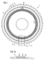
- FIG. 1 is a schematic plan view of an inventive device Component belt transport wheel visible.
- the Transport wheel 1 has a substantially disc-shaped Body 12, which with a plurality of transport pins 13th is provided, which are each arranged radially extending are.
- the transport pins 13 are suitable for Transport of component belts in their transport openings intervene to allow translation of the component straps, which is caused by a rotation of the transport wheel becomes.
- a Enkoderrad 14 On the disc-shaped body 12 is, for example in a annular recess, a Enkoderrad 14 attached.
- the encoder wheel 14 is fixedly coupled to the body 12, so that a clear assignment of the transport pins 13 to the Enkoder instituten the Enkoderrads 14 is possible.
- Bauelementgurt-transport wheel 1 to a sensor 16 passes, which the Enkoder institute the Enkoderrads 14 is in cooperation with the sensor 16 the position of the encoder wheel 14 and thus the position of the Transport wheel 1 to a fixed reference point, such as the position of the sensor 16, uniquely determined.
- a marker 18 may be formed in the body 12, for example be. As Figure 1 is designed as an opening Mark 18 can be seen. Is this at another detection unit the sensor 16 passed, a signal which indicates that a zero position or Zero position of the transport wheel 1 is taken. Of this proceeding by counting the past the sensor 16 Encoder elements of Enkoderrads 14 are found, by what angular amount the transport wheel 18 has been moved.
- the transport direction can also be detected by detecting the encoder elements the Enkoderrads 14 are read.
- the transport direction can also be detected by detecting the encoder elements the Enkoderrads 14 are read.
- For example may be when using a magnetically operating encoder wheel 14 by configuration of the poles, for example, the shape of the Pole flanks, the direction of rotation of the transport wheel 1 from the different Edge shape of the signal of the sensor 16 determined become.
- FIG. 1a shows a section through the schematic view of the transport wheel 1 along the cutting line S.
- the encoder wheel 14 is arranged.
- the encoder wheel 14 has a plurality of encoder elements 15, which from Figure 1a as a substantially number-shaped pole of a magnetizable encoder wheel 14 made of an injection molding material are shown.
- the Enkoderrad 14th as a thin magnetizable layer in which the encoder elements in the form of magnetized areas are formed.
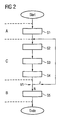
- FIG. 2 is a schematic flow diagram of the invention Method for operating a component belt transport system seen.
- the inventive method can basically in Divide three sections A, B and C.
- a and B sections which before and after the operation of the component belt transport system optional can be performed.
- C denotes the section of the actual detection the absolute position of the transport wheel 1 according to the invention with the steps S2 to S4.
- the inventive method with a starting step set in motion.
- the transport wheel 1 by means of a drive (not shown) until the mark 18 can be detected by the sensor 16.
- Starting from this Position can be passed by counting the past the sensor 16 Encoder elements 15 of the encoder wheel 14, the angular amount the rotation of the transport wheel 1 relative to the sensor 16 be recorded. Detecting the zero position in step 1 however, is not mandatory.
- step 2 the Signal of the sensor 16 detected.
- the detected signal is in Step S3 evaluated.
- a step S4 the detected angle amount and the determined direction of rotation, for example, to a control device for a component belt transport system. If the operation is to continue, this is by a yes (J) decided in a step V1 and there is a return before step S2, where the inventive method according to section C, as shown in FIG. 2, repeated. If there is no (N) in the decision step V1 can either in a step S5 the storage of Number of encoder elements moved past the sensor 16 15 done or it follows directly the end of the invention Process.
Landscapes
- Engineering & Computer Science (AREA)
- Manufacturing & Machinery (AREA)
- Microelectronics & Electronic Packaging (AREA)
- Control Of Conveyors (AREA)
- Transmission And Conversion Of Sensor Element Output (AREA)
- Measurement Of Length, Angles, Or The Like Using Electric Or Magnetic Means (AREA)
Claims (18)
- Roue de transport de bande de composants (1) avec un corps en forme de disque (12) à partir duquel plusieurs broches de transport (13) s'étendent chacune radialement et peuvent pénétrer lors du transport de bandes de composants dans leurs ouvertures de transport, caractérisée en ce qu'il est agencé sur le corps (12) une roue de codage (14) par laquelle la position de la roue de transport (1) peut être déterminée sans équivoque en collaboration avec un capteur (16) détectant la position de la roue de codage (14).
- Roue de transport de bande de composants selon la revendication 1, la roue de codage (14) constituant conjointement avec le capteur (16) un enregistreur angulaire incrémentiel.
- Roue de transport de bande de composants selon la revendication 1 ou 2, la roue de codage (14) comportant des aimants permanents dont les pôles (15) s'étendent dans la direction radiale de la roue de transport de bande de composants (1) et sont conçus avec des polarités alternées de manière circonférentielle sur la roue de codage (14).
- Roue de transport de bande de composants selon la revendication 3, la roue de codage (14) comportant une mince couche magnétisable dans laquelle les pôles sont conçus.
- Roue de transport de bande de composants selon la revendication 3, la roue de codage (14) comportant un matériau magnétisable, notamment un matériau à mouler par injection, à partir duquel les pôles (15) de la roue de codage (14) sont conçus à la manière de dents.
- Roue de transport de bande de composants selon l'une des revendications 1 à 5, la roue de transport (1) étant munie d'un repère (18) qui est utilisable pour déterminer une position neutre.
- Roue de transport de bande de composants selon la revendication 6, le repère (18) étant une ouverture qui est conçue dans la roue de transport (1) et qui est agencée à proximité de la roue de codage (14).
- Roue de transport de bande de composants selon l'une des revendications 1 à 7, un élément de couplage étant prévu en plus pour l'entraínement de la roue de transport (1).
- Roue de transport de bande de composants selon la revendication 8, l'élément de couplage étant une roue tangente.
- Roue de transport de bande de composants selon l'une des revendications 1 à 9, au moins les broches de transport (13) comportant un revêtement en plastique.
- Système de transport de bande de composants avec une roue de transport de bande de composants (1) selon l'une des revendications 1 à 10, avec un élément de guidage qui guide la bande de composants relativement à la roue de transport, avec un capteur (16) pour la détection de la position relative de la roue de codage (14) relativement au capteur (16), avec un entraínement pour le déplacement de la roue de transport de bande de composants (1) autour de son axe de rotation, avec une transmission reliée à l'entraínement pour la transmission de la force d'entraínement à la roue de transport de bande de composants (1), la résolution angulaire du capteur (16) en relation avec la roue de codage (14) étant plus fine que le jeu angulaire de la roue de transport (1) qui est dû à l'entraínement et/ou à la transmission.
- Système de transport de bande de composants selon la revendication 11, en plus avec un dispositif de commande qui forme conjointement avec l'entraínement et avec le capteur (16) un circuit de régulation fermé.
- Système de transport de bande de composants selon la revendication 12, le dispositif de commande comportant une mémoire de données dans laquelle sont enregistrées des données concernant l'association géométrique des broches de transport (13) à la roue de codage (14).
- Procédé pour faire fonctionner un système de transport de bande de composants selon l'une des revendications 11 à 13, selon lequel on détermine la position angulaire des broches de transporten déterminant une fraction de la distance angulaire entre deux éléments de codage (15) voisins à partir de positions relatives d'éléments de codage par rapport au capteur (16)et en détectant une valeur de comptage qui est un nombre entier de distances angulaires entre deux éléments de codage voisins.
- Procédé selon la revendication 14, selon lequel on détecte préalablement les associations géométriques des broches de transport (13) à des éléments de codage (15) voisins respectifs pour déterminer des irrégularités.
- Procédé selon la revendication 15, selon lequel on mémorise les irrégularités déterminées.
- Procédé selon la revendication 16, selon lequel, lors de la détermination de la position angulaire des broches de transport (13), on prend en compte les irrégularités déterminées.
- Procédé selon l'une des revendications 14 à 17, selon lequel on mémorise le dernier nombre entier déterminé de distances angulaires entre deux éléments de codage (15) voisins avant de mettre fin au fonctionnement du système de transport de bande de composants.
Applications Claiming Priority (3)
| Application Number | Priority Date | Filing Date | Title |
|---|---|---|---|
| DE10224998 | 2002-06-05 | ||
| DE10224998A DE10224998A1 (de) | 2002-06-05 | 2002-06-05 | Bauelementegurt-Transportrad, Bauelementegurt-Transportsystem und Verfahren zum Betreiben eines Bauelementegurt-Transportsystems |
| PCT/DE2003/001821 WO2003105556A1 (fr) | 2002-06-05 | 2003-06-02 | Roue transporteuse a courroie a elements, systeme transporteur a courroie a elements et procede d'exploitation d'un systeme transporteur a courroie a elements |
Publications (2)
| Publication Number | Publication Date |
|---|---|
| EP1510115A1 EP1510115A1 (fr) | 2005-03-02 |
| EP1510115B1 true EP1510115B1 (fr) | 2005-11-23 |
Family
ID=29594286
Family Applications (1)
| Application Number | Title | Priority Date | Filing Date |
|---|---|---|---|
| EP03756961A Expired - Lifetime EP1510115B1 (fr) | 2002-06-05 | 2003-06-02 | Roue transporteuse a courroie a elements, systeme transporteur a courroie a elements et procede d'exploitation d'un systeme transporteur a courroie a elements |
Country Status (7)
| Country | Link |
|---|---|
| US (1) | US6905013B2 (fr) |
| EP (1) | EP1510115B1 (fr) |
| JP (1) | JP2005534165A (fr) |
| KR (1) | KR20050014002A (fr) |
| CN (1) | CN100361564C (fr) |
| DE (2) | DE10224998A1 (fr) |
| WO (1) | WO2003105556A1 (fr) |
Families Citing this family (12)
| Publication number | Priority date | Publication date | Assignee | Title |
|---|---|---|---|---|
| US7073696B2 (en) * | 2003-11-24 | 2006-07-11 | Tyco Electronics Corporation | High repeatability tape feeder for electronic component carrier tapes |
| DE102005006400A1 (de) * | 2005-02-11 | 2006-08-24 | Siemens Ag | Verfahren zum Zuführen von Bauelementen und Bestückautomat |
| ATE401200T1 (de) * | 2005-10-27 | 2008-08-15 | Oce Tech Bv | Antriebsmechanismus für eine zuführrolle in einem drucker |
| DE102006024733B3 (de) | 2006-05-26 | 2007-09-06 | Maxon Motor Ag | Feedereinschub für Bestückungsmaschinen von Leiterplatten |
| JP2011060809A (ja) * | 2009-09-07 | 2011-03-24 | Juki Corp | 電子部品フィーダ |
| CN102026533B (zh) * | 2009-09-09 | 2015-01-28 | Juki株式会社 | 部件供给装置 |
| DE202010007285U1 (de) * | 2010-05-21 | 2011-09-23 | Balluff Gmbh | Maßkörpervorrichtung für ein Positions-/Wegmesssystem, Positions-/Wegmesssystem und Anwendung, an welcher ein Positions-/Wegmesssystem montiert ist |
| CN102271488B (zh) * | 2011-07-12 | 2015-07-08 | 广东工业大学 | 一种用于贴片机的轻型带式送料器 |
| CN102297081B (zh) * | 2011-09-09 | 2013-06-05 | 广东明阳风电产业集团有限公司 | 一种风力发电机组变桨编码器 |
| EP2905882B1 (fr) * | 2014-02-10 | 2022-03-30 | Siemens Aktiengesellschaft | Détection d'un état cinématique d'un composant de machine rotatif |
| DE102014106543A1 (de) * | 2014-05-09 | 2015-11-12 | Asm Assembly Systems Gmbh & Co. Kg | Gurtförderer für einen Bestückautomaten sowie Bestückautomat |
| CN111656880B (zh) * | 2018-04-27 | 2021-06-25 | 株式会社富士 | 载带输送装置及载带输送方法 |
Citations (1)
| Publication number | Priority date | Publication date | Assignee | Title |
|---|---|---|---|---|
| WO2003101172A1 (fr) * | 2002-05-24 | 2003-12-04 | Delaware Capital Formation, Inc. | Dispositif d'alimentation de bande a composants a chargement automatique |
Family Cites Families (12)
| Publication number | Priority date | Publication date | Assignee | Title |
|---|---|---|---|---|
| US4476504A (en) * | 1981-05-04 | 1984-10-09 | Georges Michael P | Data cartridge tape drive assembly |
| US4899048A (en) * | 1987-04-27 | 1990-02-06 | Printware, Inc. | Focused optical beam encoder of position |
| DE3736530A1 (de) * | 1987-10-28 | 1989-05-11 | Siemens Ag | Antriebseinheit zum schrittweisen laengstransport von magazinen oder gurten |
| EP0589275B1 (fr) * | 1992-09-23 | 1995-05-31 | Siemens Aktiengesellschaft | Dispositif d'amenée de composants du type SMD insérés dans une bande |
| US5323286A (en) * | 1992-12-31 | 1994-06-21 | Xerox Corporation | Method of determining tape length and tape pack position of a tape cassette |
| US5608584A (en) * | 1995-05-25 | 1997-03-04 | Quantum Corporation | Recognition of tape recording media type using plural in-line holes |
| JP4197549B2 (ja) * | 1998-06-24 | 2008-12-17 | 富士機械製造株式会社 | 電気部品供給装置およびプリント回路板組立方法 |
| US6032845A (en) | 1998-10-15 | 2000-03-07 | Hover-Davis, Inc. | Variable pitch tape feeder and pitch selection switch therefor |
| JP2002535172A (ja) * | 1999-01-25 | 2002-10-22 | ファーゴ・エレクトロニクス・インコーポレーテッド | サプライ用品 |
| DE19906222C1 (de) * | 1999-02-15 | 2000-07-20 | Siemens Ag | Zuführeinrichtung für gegurtete SMD-Bauelemente |
| US6591483B1 (en) * | 2000-04-04 | 2003-07-15 | The Cherry Corporation | Method of forming a spatially fine magnetic structure |
| DE10048458B4 (de) | 2000-09-29 | 2004-11-11 | Siemens Ag | Zuführeinrichtung für mit Bestückelementen beladene Transportbänder |
-
2002
- 2002-06-05 DE DE10224998A patent/DE10224998A1/de not_active Withdrawn
-
2003
- 2003-01-23 US US10/348,900 patent/US6905013B2/en not_active Expired - Fee Related
- 2003-06-02 EP EP03756961A patent/EP1510115B1/fr not_active Expired - Lifetime
- 2003-06-02 CN CNB038131005A patent/CN100361564C/zh not_active Expired - Fee Related
- 2003-06-02 JP JP2004512478A patent/JP2005534165A/ja not_active Withdrawn
- 2003-06-02 KR KR10-2004-7019783A patent/KR20050014002A/ko not_active Application Discontinuation
- 2003-06-02 WO PCT/DE2003/001821 patent/WO2003105556A1/fr active IP Right Grant
- 2003-06-02 DE DE50301760T patent/DE50301760D1/de not_active Expired - Fee Related
Patent Citations (1)
| Publication number | Priority date | Publication date | Assignee | Title |
|---|---|---|---|---|
| WO2003101172A1 (fr) * | 2002-05-24 | 2003-12-04 | Delaware Capital Formation, Inc. | Dispositif d'alimentation de bande a composants a chargement automatique |
Also Published As
| Publication number | Publication date |
|---|---|
| WO2003105556A1 (fr) | 2003-12-18 |
| CN1659945A (zh) | 2005-08-24 |
| KR20050014002A (ko) | 2005-02-05 |
| JP2005534165A (ja) | 2005-11-10 |
| DE50301760D1 (de) | 2005-12-29 |
| CN100361564C (zh) | 2008-01-09 |
| EP1510115A1 (fr) | 2005-03-02 |
| US6905013B2 (en) | 2005-06-14 |
| DE10224998A1 (de) | 2004-01-08 |
| US20030226873A1 (en) | 2003-12-11 |
Similar Documents
| Publication | Publication Date | Title |
|---|---|---|
| EP0172323B1 (fr) | Appareil de mesure | |
| DE3144334C2 (de) | Wegmeßeinrichtung mit Referenzmarken | |
| DE60105437T2 (de) | Verfahren und vorrichtung zur regenerierung einer seitenposition eines servosystems in bezug zur langseitigen servospuren eines magnetbandes | |
| EP1646844B1 (fr) | Appareil d'injection ayant un capteur magnetoresistif | |
| EP1510115B1 (fr) | Roue transporteuse a courroie a elements, systeme transporteur a courroie a elements et procede d'exploitation d'un systeme transporteur a courroie a elements | |
| EP0085787B1 (fr) | Dispositif de mesure | |
| DE19628765B4 (de) | Verfahren und Vorrichtung zur Positionsbestimmung von nicht-geradlinig bewegten, insbesondere rotierenden Maschinenteilen | |
| EP2533018B1 (fr) | Système de mesure de trajectoire linéaire | |
| EP0555507B1 (fr) | Capteur de position | |
| EP0268558B1 (fr) | Appareil pour la mesure de longueurs ou d'angles | |
| DE3311204A1 (de) | Inkrementale laengen- oder winkelmesseinrichtung | |
| EP1141660A1 (fr) | Dispositif et procede pour la mesure de la position angulaire d'un corps rotatif | |
| DE2952106A1 (de) | Lichtelektrische inkrementale positioniereinrichtung | |
| WO2011134823A2 (fr) | Système de détection incrémentiel de positions multiples pour un système de transfert électromagnétique en boucle fermée | |
| DE3220629C2 (de) | Steuervorrichtung zur Verleimung von Endlossätzen | |
| EP1195880A1 (fr) | Procédé pour augmenter la précision de positionnement d'un élément mobile par rapport à un stator | |
| AT394781B (de) | Inkrementales messsystem | |
| DE102006060622A1 (de) | Vorrichtung zur Stellungserfassung eines sich bewegenden Bauteils | |
| CH672679A5 (fr) | ||
| DE3208591A1 (de) | Laengen- oder winkelmesssystem | |
| DE102006017865A1 (de) | Vorrichtung zur Messung der absoluten Position eines Messobjekts | |
| EP2159549B1 (fr) | Dispositif de mesure de la position relative entre une mesure matérialisée et une tête de lecture | |
| EP1006342B1 (fr) | Procédé de marquage des pistes de mesure | |
| DE10162849B4 (de) | Längenmesssystem, bei dem ein Massstab relativ zur Position von beabstandeten Längensensoren bewegt wird | |
| EP2116814B1 (fr) | Dispositif de mesure destiné à la détermination d'une position et/ou d'une vitesse |
Legal Events
| Date | Code | Title | Description |
|---|---|---|---|
| PUAI | Public reference made under article 153(3) epc to a published international application that has entered the european phase |
Free format text: ORIGINAL CODE: 0009012 |
|
| 17P | Request for examination filed |
Effective date: 20041104 |
|
| AK | Designated contracting states |
Kind code of ref document: A1 Designated state(s): AT BE BG CH CY CZ DE DK EE ES FI FR GB GR HU IE IT LI LU MC NL PT RO SE SI SK TR |
|
| GRAP | Despatch of communication of intention to grant a patent |
Free format text: ORIGINAL CODE: EPIDOSNIGR1 |
|
| RBV | Designated contracting states (corrected) |
Designated state(s): CH DE FR GB IT LI NL |
|
| GRAS | Grant fee paid |
Free format text: ORIGINAL CODE: EPIDOSNIGR3 |
|
| GRAA | (expected) grant |
Free format text: ORIGINAL CODE: 0009210 |
|
| AK | Designated contracting states |
Kind code of ref document: B1 Designated state(s): CH DE FR GB IT LI NL |
|
| REG | Reference to a national code |
Ref country code: GB Ref legal event code: FG4D Free format text: NOT ENGLISH |
|
| REG | Reference to a national code |
Ref country code: CH Ref legal event code: NV Representative=s name: SIEMENS SCHWEIZ AG Ref country code: CH Ref legal event code: EP |
|
| GBT | Gb: translation of ep patent filed (gb section 77(6)(a)/1977) |
Effective date: 20051201 |
|
| REF | Corresponds to: |
Ref document number: 50301760 Country of ref document: DE Date of ref document: 20051229 Kind code of ref document: P |
|
| ET | Fr: translation filed | ||
| PLBE | No opposition filed within time limit |
Free format text: ORIGINAL CODE: 0009261 |
|
| STAA | Information on the status of an ep patent application or granted ep patent |
Free format text: STATUS: NO OPPOSITION FILED WITHIN TIME LIMIT |
|
| 26N | No opposition filed |
Effective date: 20060824 |
|
| REG | Reference to a national code |
Ref country code: CH Ref legal event code: PCAR Free format text: SIEMENS SCHWEIZ AG;INTELLECTUAL PROPERTY FREILAGERSTRASSE 40;8047 ZUERICH (CH) |
|
| REG | Reference to a national code |
Ref country code: CH Ref legal event code: PUE Owner name: SIEMENS ELECTRONICS ASSEMBLY SYSTEMS GMBH & CO. K Free format text: SIEMENS AKTIENGESELLSCHAFT#WITTELSBACHERPLATZ 2#80333 MUENCHEN (DE) -TRANSFER TO- SIEMENS ELECTRONICS ASSEMBLY SYSTEMS GMBH & CO. KG#RUPERT-MAYER-STRASSE 44#81379 MUENCHEN (DE) |
|
| REG | Reference to a national code |
Ref country code: GB Ref legal event code: 732E Free format text: REGISTERED BETWEEN 20090903 AND 20090909 |
|
| PGFP | Annual fee paid to national office [announced via postgrant information from national office to epo] |
Ref country code: FR Payment date: 20090821 Year of fee payment: 7 |
|
| NLS | Nl: assignments of ep-patents |
Owner name: SIEMENS ELECTRONICS ASSEMBLY SYSTEMS GMBH & CO. KG Effective date: 20090820 |
|
| PGFP | Annual fee paid to national office [announced via postgrant information from national office to epo] |
Ref country code: CH Payment date: 20090903 Year of fee payment: 7 Ref country code: DE Payment date: 20090821 Year of fee payment: 7 Ref country code: GB Payment date: 20090813 Year of fee payment: 7 Ref country code: NL Payment date: 20090814 Year of fee payment: 7 |
|
| REG | Reference to a national code |
Ref country code: FR Ref legal event code: TP |
|
| PGFP | Annual fee paid to national office [announced via postgrant information from national office to epo] |
Ref country code: IT Payment date: 20090826 Year of fee payment: 7 |
|
| REG | Reference to a national code |
Ref country code: NL Ref legal event code: V1 Effective date: 20110101 |
|
| REG | Reference to a national code |
Ref country code: CH Ref legal event code: PL |
|
| GBPC | Gb: european patent ceased through non-payment of renewal fee |
Effective date: 20100602 |
|
| REG | Reference to a national code |
Ref country code: FR Ref legal event code: ST Effective date: 20110228 |
|
| PG25 | Lapsed in a contracting state [announced via postgrant information from national office to epo] |
Ref country code: IT Free format text: LAPSE BECAUSE OF NON-PAYMENT OF DUE FEES Effective date: 20100602 |
|
| PG25 | Lapsed in a contracting state [announced via postgrant information from national office to epo] |
Ref country code: CH Free format text: LAPSE BECAUSE OF NON-PAYMENT OF DUE FEES Effective date: 20100630 Ref country code: DE Free format text: LAPSE BECAUSE OF NON-PAYMENT OF DUE FEES Effective date: 20110101 Ref country code: LI Free format text: LAPSE BECAUSE OF NON-PAYMENT OF DUE FEES Effective date: 20100630 |
|
| PG25 | Lapsed in a contracting state [announced via postgrant information from national office to epo] |
Ref country code: FR Free format text: LAPSE BECAUSE OF NON-PAYMENT OF DUE FEES Effective date: 20100630 Ref country code: NL Free format text: LAPSE BECAUSE OF NON-PAYMENT OF DUE FEES Effective date: 20110101 |
|
| PG25 | Lapsed in a contracting state [announced via postgrant information from national office to epo] |
Ref country code: GB Free format text: LAPSE BECAUSE OF NON-PAYMENT OF DUE FEES Effective date: 20100602 |