EP1509012A2 - Verfahren und Vorrichtung zur Planung von Uplinkpaketübertragung in einem mobilen Kommunikationssystem - Google Patents
Verfahren und Vorrichtung zur Planung von Uplinkpaketübertragung in einem mobilen Kommunikationssystem Download PDFInfo
- Publication number
- EP1509012A2 EP1509012A2 EP20040019726 EP04019726A EP1509012A2 EP 1509012 A2 EP1509012 A2 EP 1509012A2 EP 20040019726 EP20040019726 EP 20040019726 EP 04019726 A EP04019726 A EP 04019726A EP 1509012 A2 EP1509012 A2 EP 1509012A2
- Authority
- EP
- European Patent Office
- Prior art keywords
- buffer status
- csi
- status information
- transmission
- buffer
- Prior art date
- Legal status (The legal status is an assumption and is not a legal conclusion. Google has not performed a legal analysis and makes no representation as to the accuracy of the status listed.)
- Withdrawn
Links
Images


Classifications
-
- H—ELECTRICITY
- H04—ELECTRIC COMMUNICATION TECHNIQUE
- H04L—TRANSMISSION OF DIGITAL INFORMATION, e.g. TELEGRAPHIC COMMUNICATION
- H04L47/00—Traffic control in data switching networks
- H04L47/10—Flow control; Congestion control
- H04L47/26—Flow control; Congestion control using explicit feedback to the source, e.g. choke packets
- H04L47/266—Stopping or restarting the source, e.g. X-on or X-off
-
- H—ELECTRICITY
- H04—ELECTRIC COMMUNICATION TECHNIQUE
- H04L—TRANSMISSION OF DIGITAL INFORMATION, e.g. TELEGRAPHIC COMMUNICATION
- H04L47/00—Traffic control in data switching networks
- H04L47/10—Flow control; Congestion control
-
- H—ELECTRICITY
- H04—ELECTRIC COMMUNICATION TECHNIQUE
- H04L—TRANSMISSION OF DIGITAL INFORMATION, e.g. TELEGRAPHIC COMMUNICATION
- H04L47/00—Traffic control in data switching networks
- H04L47/10—Flow control; Congestion control
- H04L47/29—Flow control; Congestion control using a combination of thresholds
-
- H—ELECTRICITY
- H04—ELECTRIC COMMUNICATION TECHNIQUE
- H04L—TRANSMISSION OF DIGITAL INFORMATION, e.g. TELEGRAPHIC COMMUNICATION
- H04L47/00—Traffic control in data switching networks
- H04L47/10—Flow control; Congestion control
- H04L47/30—Flow control; Congestion control in combination with information about buffer occupancy at either end or at transit nodes
-
- H—ELECTRICITY
- H04—ELECTRIC COMMUNICATION TECHNIQUE
- H04W—WIRELESS COMMUNICATION NETWORKS
- H04W28/00—Network traffic management; Network resource management
- H04W28/02—Traffic management, e.g. flow control or congestion control
-
- H—ELECTRICITY
- H04—ELECTRIC COMMUNICATION TECHNIQUE
- H04W—WIRELESS COMMUNICATION NETWORKS
- H04W72/00—Local resource management
- H04W72/20—Control channels or signalling for resource management
- H04W72/21—Control channels or signalling for resource management in the uplink direction of a wireless link, i.e. towards the network
-
- H—ELECTRICITY
- H04—ELECTRIC COMMUNICATION TECHNIQUE
- H04W—WIRELESS COMMUNICATION NETWORKS
- H04W8/00—Network data management
- H04W8/02—Processing of mobility data, e.g. registration information at HLR [Home Location Register] or VLR [Visitor Location Register]; Transfer of mobility data, e.g. between HLR, VLR or external networks
- H04W8/04—Registration at HLR or HSS [Home Subscriber Server]
-
- H—ELECTRICITY
- H04—ELECTRIC COMMUNICATION TECHNIQUE
- H04W—WIRELESS COMMUNICATION NETWORKS
- H04W28/00—Network traffic management; Network resource management
- H04W28/02—Traffic management, e.g. flow control or congestion control
- H04W28/10—Flow control between communication endpoints
- H04W28/14—Flow control between communication endpoints using intermediate storage
-
- H—ELECTRICITY
- H04—ELECTRIC COMMUNICATION TECHNIQUE
- H04W—WIRELESS COMMUNICATION NETWORKS
- H04W72/00—Local resource management
- H04W72/50—Allocation or scheduling criteria for wireless resources
- H04W72/52—Allocation or scheduling criteria for wireless resources based on load
Definitions
- the present invention relates generally to a mobile communication system, and in particular, to a method and apparatus for efficiently transmitting and receiving scheduling information and scheduling assignment information for uplink packet transmission.
- An asynchronous WCDMA (Wideband Code Division Multiple Access) communication system uses an EUDCH (Enhanced Uplink Dedicated CHannel) to provide a high-rate packet data service is an uplink direction.
- the EUDCH was designed to improve the performance of uplink packet transmission.
- HSDPA High Speed Downlink Packet Access
- AMC Adaptive Modulation and Coding
- HARQ Hybrid Automatic Retransmission request
- the EUDCH technology utilizes new techniques using a short TTI (Transmission Time Interval).
- Node B controlled scheduling is applied to uplink channels. The Node B controlled uplink scheduling is very different from downlink scheduling.
- FIGS. 1A and 1B are graphs illustrating changes in uplink radio resources available to the Node B.
- the uplink radio resources are the sum of ICI (Inter-Cell Interference), voice traffic, and EUDCH packet traffic.
- FIG. 1A illustrates changes in a total ROT when Node B controlled scheduling is not used.
- a plurality of UEs may simultaneously transmit data at high rates.
- the total ROT exceeds a target ROT and the reception performance of the UL signals is degraded.
- FIG. 1B illustrates changes in the total ROT when the Node B controlled scheduling is used.
- the Node B controlled scheduling prevents the UEs from simultaneously transmitting data at high rates. When a high rate is allowed for a particular UE, low rates are allowed for other UEs, such that the total ROT does not exceed the target ROT. Accordingly, the Node B controlled scheduling ensures a constant reception performance.
- the Node B uses the EUDCH to notifies UEs if EUDCH data transmission is available, or adjusts EUDCH data rates for them, utilizing requested data rates or CSI (Channel State Information) representing uplink quality from the UEs.
- CSI Channel State Information
- the Node B assigns data rates to the UEs such that the total ROT does not exceed the target ROT, thereby improving system performance.
- the Node B can assign a low data rate to a remote (or far away) UE, and a high data rate to a nearby UE.
- FIG. 2 illustrates a basic concept of the Node B controlled scheduling of the EUDCH.
- reference numeral 200 denotes a Node B supporting the EUDCH and reference numerals 210 to 216 denote UEs using the EUDCH.
- the Node B receives data from the UE at an increased reception power. Therefore, the ROT of the UE contributes more to the total ROT. If the data rate of another UE decreases, the Node B receives data from the UE at a decreased reception power. Therefore, the ROT of the UE contributes less to the total ROT.
- the Node B schedules the EUDCH packet data considering the relationship between data rates and radio resources and UEs-requested data rates.
- the UEs 210 to 216 transmit packet data at different uplink transmit power levels according to the distances between them and the Node B 200.
- the farthest UE 210 transmits packet data at the highest uplink transmit power level 220, while the nearest UE 214 transmits packet data at the lowest uplink transmit power level 224.
- the Node B schedules uplink data transmission in the manner that makes the transmit power of the uplink channel is inversely proportional to its data rate in order to improve system performance, while maintaining the total ROT and reducing ICI. Accordingly, the Node B assigns a relatively low data rate to the UE 210 having the highest transmit power and a relative high data rate to the UE 214 having the lowest transmit power.
- FIG. 3 illustrates an operation for being assigned a data rate for EUDCH packet transmission and transmitting packet data at the assigned data rate in a UE.
- an EUDCH is established between a Node B 300 and a UE 302 in step 310.
- Step 310 involves transmission and reception of messages on dedicated transport channels.
- the UE 302 notifies the Node B 300 of a desired data rate, buffer status information, and uplink CSI.
- the uplink CSI includes the uplink transmit power or/and transmit power margin of the UE 302.
- the Node B 300 estimates the uplink channel state by comparing the uplink transmit power with uplink received power. If the difference between the uplink transmit power and the uplink received power is small, the uplink channel state is good. If the difference is large, the uplink channel state is bad.
- the Node B 300 estimates the uplink transmit power by subtracting the transmit power margin from a known maximum available transmit power of the UE 302. The Node B 300 determines a maximum available data rate for the UE based on the estimated uplink channel state and the requested data rate.
- the Node B 300 notifies the UE 302 of the maximum data rate by scheduling assignment information.
- the UE 302 selects a data rate that is equal to or less than the maximum data rate and transmits packet data at the selected data rate to the Node B 300 in step 316.
- the UE 302 To transmit all packet data of an EUDCH data buffer to the Node B 300, the UE 302 must receive the scheduling assignment information from the Node B 300 at every predetermined interval. However, when the UE 302 transmits buffer status information and CSI at every scheduling interval, the resulting signaling overhead decreases the efficiency of uplink packet transmission. Therefore, there is a need for an efficient scheduling scheme to decrease the uplink signaling overhead.
- an object of the present invention is to provide a method and apparatus for reducing uplink signaling overhead during uplink packet transmission.
- Another object of the present invention is to provide a method and apparatus for controlling the transmission intervals of buffer status information and CSI on the uplink to reduce signaling overhead.
- a further object of the present invention is to provide a method and apparatus for efficiently transmitting uplink packets by controlling the transmission intervals of buffer status information and CSI.
- Still another object of the present invention is to provide a method and apparatus for efficiently utilizing radio resources by controlling the transmission intervals of buffer status information and CSI.
- the above and other objects are achieved by providing a method and apparatus for transmitting and receiving buffer status information and CSI for scheduling an uplink packet data service in a mobile communication system .
- the buffer status information represents the status of a buffer for storing packet data to be transmitted and the CSI represents the uplink transmit power of the UE.
- the UE monitors the amount of packet data stored in the buffer. If the data amount is at least equal to a predetermined threshold, the UE initially transmits the buffer status information and the CSI. After the initial transmission of the buffer status information and the CSI, the UE transmits the buffer status information upon generation of new packet data in the buffer.
- the UE monitors the amount of packet data stored in the buffer. If the data amount is at least equal to a predetermined threshold, the UE initially transmits the buffer status information and the CSI. Upon generation of new packet data in the buffer after the initial transmission of the buffer status information and the CSI, the UE transmits the buffer status information according to a predetermined buffer status transmission interval.
- the UE waits until a first buffer status transmission time point among buffer status transmission time points determined according to a predetermined buffer status interval.
- the UE monitors the amount of packet data stored in the buffer at the buffer status transmission time point. If the data amount is at least equal to a predetermined threshold, the UE initially transmits the buffer status information and the CSI. After the initial transmission of the buffer status information and the CSI, the UE determines if new packet data is generated in the buffer at a second buffer status transmission time point. Upon generation of the new packet data in the buffer at the second buffer status transmission time point, the UE transmits the buffer status information.
- the UE monitors the amount of packet data stored in the buffer. If the data amount is at least equal to a predetermined threshold, the UE initially transmits the buffer status information and the CSI, and activates a timer set to a predetermined buffer status transmission interval. Upon generation of new packet data in the buffer and reactivating the timer, the UE transmits the buffer status information. Upon expiration of the timer, the UE transmits the buffer status information and reactivates the timer.
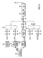
- FIG 4 is a block diagram of a transmitter in a UE supporting the EUDCH service.
- Uplink physical channels available to the UE are a DPDCH (Dedicated Physical Data Channel), an EU-DPDCH, which is a DPDCH used for the EUDCH service, a DPCCH (Dedicated Physical Control Channel), an HS-DPCCH (High Speed DPCCH) for HSDPA service, and an EU-DPCCH, which is a DPCCH used for the EUDCH service.
- DPDCH Dedicated Physical Data Channel
- EU-DPDCH Dedicated Physical Control Channel
- HS-DPCCH High Speed DPCCH
- EU-DPCCH which is a DPCCH used for the EUDCH service.
- the EU-DPCCH delivers the buffer status information and CSI of a UE.
- the CSI includes an uplink transmit power and an uplink transmit power margin required for a Node B to estimate the uplink channel state of the UE.
- the EU-DPCCH delivers an E-TFRI (EUDCH-Transport Format and Resource Indicator) that represents the transport format of the EU-DPDCH including the used data size, data rate, and modulation scheme.
- E-TFRI EUDCH-Transport Format and Resource Indicator
- the EU-DPDCH conveys packet data at a data rate that is determined according to scheduling assignment information received from the Node B.
- the DPDCH supports BPSK (Binary Phase Shift Keying) only
- the EU-DPDCH additionally supports higher- order modulations such as QPSK (Quadrature Phase Shift Keying) and 8PSK (8-ary PSK) to increase data rate while maintaining the number of simultaneous spreading codes.
- an EUDCH transmission controller 404 monitors an EUDCH data buffer 400 having data to be transmitted on the EUDCH and acquires buffer status information required for Node B control scheduling. Further, the EUDCH transmission controller 404 acquires CSI from an uplink transmission path (not shown). The EUDCH transmission controller 404 determines an E-TFRI representing the transport format of EUDCH packet data. The E-TFRI is determined according to a maximum data rate allowed by a scheduling assigner 402. The EUDCH transmission controller 404 generates EU-DPCCH data including the buffer status information, CSI, and E-TFRI, and outputs it to a spreader 408.
- DPDCH data is spread at a chip rate with an OVSF (Orthogonal Variable Spreading Factor) code assigned to the DPDCH in a spreader 422, multiplied by a channel gain in a gain adjuster 424, and applied to the input of a summer 426.
- the EU-DPCCH data is spread at a chip rate with an OVSF code assigned to the EU-DPCCH in the spreader 408, multiplied by a channel gain in a gain adjuster 410, and applied to the input of the summer 426.
- the summer 426 sums the outputs of the gain adjusters 424 and 410 and transmits the sum to a summer 420 to assign the sum to an I channel.
- An EUDCH packet transmitter 406 reads as much packet data as indicated by the E-TFRI from the EUDCH data buffer 400 and encodes the packet data according to the E-TFRI, thereby producing EU-DPDCH data.
- a modulation mapper 412 modulates the EU-DPDCH data in BPSK, QPSK, or 8PSK and outputs an EU-DPDCH modulation symbol sequence.
- BPSK modulation symbols have real number values
- QPSK and 8PSK modulation symbols have complex number values. It is to be appreciated that the following description is made in the context of using QPSK or 8PSK for the EU-DPDCH by way of example.
- the modulation mapper 412 converts the EU-DPDCH data to a complex symbol sequence.
- a spreader 414 spreads the modulation symbol sequence at a chip rate with an OVSF code assigned to the EU-DPDCH.
- the spread EU-DPDCH signal is multiplied by a channel gain in a gain adjuster 418 and applied to the input of the summer 420.
- DPCCH data which is control information of the DPDCH
- DPCCH data is spread at a chip rate with an OVSF code assigned to the DPCCH in a spreader 428, multiplied by a channel gain in a gain adjuster 430, and applied to the input of a summer 436.
- HS-DPCCH data which is control information for an HSDPA service, is spread at a chip rate with an OVSF code assigned to the HS-DPCCH in a spreader 432, multiplied by a channel gain in a gain adjuster 434, and applied to the input of the summer 436.
- the summer 436 sums the outputs of the gain adjusters 430 and 434 and transmits the sum to a phase adjuster 438 to assign the sum to a Q channel.
- the phase adjuster 438 multiplies the output of the summer 436 by a phase variation j.
- the summer 420 sums the outputs of the summer 426, the gain adjuster 418, and the phase adjuster 438, and outputs the resulting complex symbol sequence to a scrambler 442.
- the scrambler 442 scrambles the complex symbol sequence with a scrambling code.
- the scrambled complex symbol sequence is converted in the form of pulses in a pulse shaping filter 444 and transmitted to the Node B through an RF (Radio Frequency) processor 446 and an antenna 448.
- RF Radio Frequency
- FIG 5A illustrates the format of the EU-SCHCCH for delivering EUDCH scheduling assignment information
- FIG 5B is a block diagram illustrating an EU-SCHCCH transmitter.
- the EU-SCHCCH delivers scheduling assignment information 500 including Scheduling Grant/Release Messages and allowed maximum data rates to a plurality of UEs, using one OVSF code.
- a Scheduling Grant/Release Message indicates if the EUDCH packet data is transmitted.
- the scheduling assignment information 500 includes the IDs of the UEs for which the Scheduling Grant/Release Messages and the allowed maximum data rates are destined.
- a serial-to-parallel converter 510 converts the EU-SCHCCH data including the scheduling assignment information 500 to parallel symbol sequences.
- a modulation mapper 512 converts the parallel symbol sequences to I and Q streams.
- Spreaders 514 and 516 spread the I and Q streams with an OVSF code assigned to the EU-SHCCH at a chip rate.
- a phase adjuster 518 multiplies the Q stream received from the spreader 516 by the phase variation j.
- a summer 520 sums the outputs of the spreader 514 and the phase adjuster 518.
- a scrambler 522 scrambles the complex symbol sequence received from the summer 520 with a scrambling code. The scrambled complex symbol sequence is converted to pulse form in a pulse shaping filter 524 and transmitted to the UEs through an RF processor 526 and an antenna 528.
- FIG 6 illustrates continuous transmission of buffer status information and CSI from a UE to a Node B and transmission of scheduling assignment information from the Node B to the UE in a typical EUDCH system.
- the UE transmits the buffer status information and CSI to the Node B at every predetermined interval (i.e., scheduling interval T sch_int ) to receive the scheduling assignment information.
- packet data destined for the Node B is stored (generated) in the EUDCH data buffer of the UE at a time 600.
- the UE transmits to the Node B buffer status information indicating the data amount of the data buffer and CSI representing an uplink transmit power and a transmit power margin.
- the Node B determines a maximum data rate for the UE based on the buffer status information and CSI and transmits the maximum data rate to the UE by scheduling assignment information for a time period 610.
- the UE When all the packet data stored in the EUDCH data buffer cannot be transmitted to the Node B at one time, the UE continuously transmits the buffer status information and CSI at the scheduling interval T sch_int from the time period 602 through a time 606 in order to request scheduling assignment to the Node B.
- the packet data is completely transmitted to the Node B by the time 606. Therefore, after the time 606, the UE discontinues transmission of the buffer status information and CSI.
- the Node B although receiving the buffer status information and CSI from the UE, does not transmit the scheduling assignment information for a time period 612 if an ROT condition is not satisfied.
- the transmission of the buffer status information and CSI at every scheduling interval significantly increases uplink overhead and reduces uplink traffic capacity. Therefore, in a preferred embodiment of the present invention, different transmission intervals are set for the buffer status information and the CSI.
- the Node B estimates the buffer state information and CSI of the UE using an E-TFRI received from the UE and downlink TPC (Transmit Power Control) commands transmitted to the UE.
- a TPC command orders a UE transmit power increase/decrease. Therefore, the Node B estimates the current transmit power of the UE by adding transmit power calculated from the last reported CSI and as many power increment/decrement units as the number of TPS commands transmitted to the UE. Also, the Node B estimates the current buffer status of the UE by subtracting a data mount calculated by the E-TFRI from a data amount calculated using the last reported buffer status of the UE.
- the E-TFRI is very significant for reception of EUDCH data. It is typically set to have a lower error rate than a TPC command. Therefore, the estimate of the buffer status is relatively reliable compared to the transmit power estimate. Accordingly, the transmission interval of the buffer status information is longer than the CSI transmission interval.
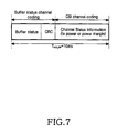
- FIG 7 illustrates a code block including buffer status information and CSI transmitted from a UE according to a preferred embodiment of the present invention.
- the buffer status information and CSI are transmitted in one scheduling interval, T sch_int .
- the scheduling interval is 10ms in duration.
- the buffer status information is transmitted to the Node B only when new data is generated in the EUDCH data buffer. That is, transmission of the buffer state information is event-triggered. Accordingly, the UE channel-encodes the buffer status information and the CSI through different channel coding chains.
- the buffer status information is attached with a CRC (Cyclic Redundancy Code) and then channel-encoded, whereas the CSI is directly channel-encoded without CRC attachment.
- the Node B determines that the buffer status information has been received by a CRC check. Because the CSI follows the buffer status information, a decision as to if the CSI has been received depends on the buffer status information being received.
- the CRC can be common to the buffer status information and the CSI.
- the UE operates as follows.
- the Node B operates as follows.
- FIG. 8 illustrates EU-DPCCH signaling for scheduling assignment between the UE and the Node B according to an embodiment of the present invention.
- T sch_int denotes a scheduling interval and each scheduling interval is divided into a buffer status information part and a CSI part.
- the Node B generates scheduling assignment information based on the buffer status information and the CSI and transmits the scheduling assignment information in a time period 814.
- An ROT is considered in determining the scheduling assignment information.
- the UE After the transmission of the buffer status information, the UE awaits reception of scheduling assignment information from the Node B.
- a predetermined time i.e., the buffer retransmission interval T bs,re
- the Node B estimates the amount of transmission packet data of the UE and, if the estimated data amount is less than the threshold, transmits a Scheduling Release message to the UE.
- the UE discontinues transmission of the buffer status information and CSI to the Node B.
- the UE discontinues transmission of the buffer status information and CSI to the Node B.
- FIG. 9 is a block diagram of an EUDCH transmission controller 900 in the UE according to the embodiment of the present invention.
- a transmission start and end decider 902 decides the start and end of transmission of buffer status information and CSI.
- the transmission start is determined by comparing input buffer status information with a predetermined threshold. If the buffer status information indicating the amount of packet data stored in the EUDCH data buffer is at least equal to the threshold, the transmission start and end decider 902 outputs a start signal, determining that it is time to start to transmit the buffer status information and the CSI.
- the transmission end is a time when a Scheduling Release message is received from the Node B.
- the transmission start and end decider 902 outputs an end signal, determining that it is time to terminate the transmission of the buffer status information and the CSI.
- a transmission time decider 904 upon receiving the start signal from the transmission start and end decider 902, determines the transmission time points of the buffer status information and CSI.
- the transmission time points are represented by CNT sch_int as illustrated in FIG. 8.
- the transmission time decider 904 activates a buffer status switch 906 and a CSI switch 912 in scheduling intervals corresponding to the transmission time points of the buffer status information and the CSI.
- the transmission time decider 904 activates the CSI switch 912 to periodically transmit the CSI in scheduling intervals, which are determined according to T CSI .
- the transmission time decider 904 activates the buffer status switch 906.
- the transmission time decider 904 controls the buffer status switch 906 and the CSI switch 912 according to a scheduling assignment receive indication and T bs,re .
- the transmission time decider 904 activates the buffer status switch 906.
- the transmission time decider 904 simultaneously activates the buffer status switch 906 and the CSI switch 912.
- the buffer status switch 906 As the buffer status switch 906 is activates, it switches the buffer status information to a CRC adder 908. The buffer status information is attached with a CRC in the CRC adder 908 and channel-encoded in a channel encoder 910. The channel-coded buffer status information is applied to the input of a multiplexer (MUX) 922. As the CSI switch 912 is activates, it switches the CSI to a channel encoder 914. The CSI is channel-encoded in the channel encoder 914 and input to the MUX 922.
- MUX multiplexer
- An EUDCH TF (Transport Format) decider 916 determines the TF of packet data for the EUDCH service based on the scheduling assignment information received from the Node B and generates an E-TFRI representing the determined TF.
- the E-TFRI is added with CRC bits in a CRC adder 918 and channel-encoded in a channel encoder 920.
- the channel-coded E-TFRI is input to the MUX 922.
- the MUX 922 multiplexes the coded buffer status information, CSI and E-TFRI and transmits the multiplexed signal on the EU-DPCCH.
- An EUDCH packet transmitter 924 transmits the packet data stored in the EUDCH data buffer according to the TF decided by the EUDCH TF decider 916.
- FIG. 10 is a flowchart illustrating an operation of a transmitter in the UE according to the embodiment of the present invention.
- the UE monitors its buffer status, that is, the amount of data stored in the EUDCH data buffer in step 1000 and determines if the data amount is at least equal to the threshold.
- THRES buffer in step 1002. If the data amount is at least equal to THRES buffer , the UE proceeds to step 1006. If the data amount is less than THRES buffer , the UE proceeds to step 1004. In step 1004, the UE waits until the next scheduling interval, and returns to step 1000 to monitor the EUDCH data buffer.
- step 1006 the UE transmits buffer status information and CSI to the Node B, waits until the next scheduling interval in step 1008, and monitors the EUDCH data buffer in step 1010.
- step 1012 the UE determines whether or not to continue transmitting the buffer status information and the CSI. The determination is made by comparing the amount of packet data stored in the EUDCH data buffer with THRES buffer . If the data amount is still at least equal to THRES buffer, the UE proceeds to step 1014 to continue transmitting the buffer status information and the CSI. If the data amount is less than THRES buffer, the UE proceeds to step 1024. In step 1024, the UE determines whether or not to continue the EUDCH data service. If the UE determines to continue the EUDCH data service, it waits until the next scheduling interval in step 1026 and returns to step 1000. If the UE determines not to continue the EUDCH data service, it terminates the procedure.
- step 1014 the UE determines if new data has been generated in the EUDCH data buffer. Upon generation of the new data, the UE proceeds to step 1016; otherwise, it proceeds to step 1018.
- step 1018 the UE determines if scheduling assignment information has been received from the Node B within the buffer retransmission period T bs,re , after transmission of the previous buffer status information. If the scheduling assignment information has been received, the UE proceeds to step 1020. If the scheduling assignment information has not been received, the UB transmits the buffer status information in step 1016. Although not depicted in step 1016 in FIG. 10, if the scheduling assignment information has not been received within T bs,re after the transmission of the first buffer status information in step 1018, the UE transmits the CSI along with the buffer status information.
- step 1020 the UE determines if the current scheduling interval is a transmission time point of the CSI determined by a CSI transmission interval received from the RNC. If the current scheduling index is identical to a transmission time of the CSI, the UE transmits the CSI in step 1022 and returns to step 1008. However, if the CSI is not supposed to be transmitted in the current scheduling interval, the UE returns to step 1008.
- FIG. 11 is a block diagram illustrating a receiver in the Node B for receiving the buffer status information and CSI according to the embodiment of the present invention.
- an antenna 1100 receives an RF signal from the UE.
- An RF processor 1102 downconverts the RF signal to a baseband signal.
- a pulse shaping filter 1104 converts the baseband signal to a digital signal.
- a descrambler 1106 descrambles the digital signal with a scrambling code C scramble .
- the descrambled signal is multiplied by an OVSF code C OVSF in a despreader 1108 and transmitted to a demultiplexer (DEMUX) 1112 through a channel compensator 1110.
- DEMUX demultiplexer
- the DEMUX 1112 demultiplexes a signal received from the channel compensator 1110 into coded buffer status information, CSI, and E-TFRI. Because a CSI switch 1118 is activated at a first time, the coded buffer status information and the coded CSI are provided to a buffer status channel decoder 1122 and a CSI channel decoder 1120, respectively.
- the buffer status channel decoder 1122 decodes the coded buffer status information.
- a buffer status CRC checker 1124 checks a CRC of the decoded buffer status information and provides a CRC check result to a CSI reception time controller 1132.
- the CSI reception time controller 1132 determines by the CRC check result if the buffer status information has been received from the UE. If the CRC check result is good, which implies that the buffer status information has been received from the UE, the CSI reception time controller 1132 determines that it is the first reception time of the CSI and activates the CSI switch 1118.
- the CSI reception time controller 1132 determines CSI reception times using CNT sch_int, T CSI, and THRES buffer , and activates the CSI switch 1118 in scheduling intervals corresponding to the CSI reception times.
- the CSI channel decoder 1120 channel-decodes the coded CSI.
- An EUDCH scheduler 1128 generates scheduling assignment information using the CSI received from the CSI channel decoder 1120 and the buffer status information received from the buffer status CRC checker 1124. The scheduling assignment information is transmitted to the UE on the EU-SCHCCH.
- An E-TFRI channel decoder 1114 channel-decodes the coded E-TFRI received from the DEMUX 1112.
- An E-TFRI CRC checker 1116 checks a CRC of the E-TFRI. If the CRC check result is good, the E-TFRI is provided to an EUDCH data decoder 1126.
- the EUDCH data decoder 1126 decodes EUDCH data received on the EU-DPDCH from the UE using the E-TFRI.
- a UE buffer status estimator 1130 estimates the buffer status of the UE using the buffer status information received from the buffer status CRC checker 1124 and the E-TFRI received from the E-TFRI CRC checker 1116. The buffer status estimate is provided to the CSI reception time controller 1132. If the buffer status estimate is less than THRES buffer , the CSI reception time controller 1132 determines that it is time to terminate the reception of the buffer status information and the CSI and controls the EU-SCHCCH transmitter illustrated in FIG. 5B to transmit a Scheduling Release message to the UE.
- FIG 12 is a flowchart illustrating an operation for receiving buffer status information and CSI in the Node B according to the embodiment of the present invention.
- the Node B channel-decodes coded buffer status information received from the UE in step 1200 and CRC-checks the decoded buffer status information in step 1202. Using the CRC check result, the Node B determines if the UE has transmitted the buffer status information in the current scheduling interval in step 1204. If the CRC check is passed, i.e., the UE has transmitted the buffer status information in the current scheduling interval, the buffer status information is provided to the EUDCH scheduler and the Node B proceeds to step 1206. If the CRC check is failed, the Node B waits until the next scheduling interval in step 1208 and returns to step 1200.
- step 1206 the Node B channel-decodes coded CSI following the buffer status information, provides the decoded CSI to the EUDCH scheduler and in step 1210, and waits until the next scheduling interval.
- the Node B decodes coded buffer status information received from the UE in step 1212 and CRC-checks the decoded buffer status information in step 1214. If the CRC check is passed, the buffer status information is provided to the EUDCH scheduler and the Node B goes to step 1216.
- the Node B estimates the buffer status of the UE using the last received buffer status information and the amount of received data.
- the received data amount is known from the E-TFRI and the buffer status is estimated by subtracting the received data amount from the last received buffer status information. Because the CRC is passed in step 1214, the last buffer status information is the buffer status information, which was channel-decoded in step 1212.
- step 1218 the Node B determines if the buffer status estimate is at least equal to THRES buffer , If the buffer status estimate is at least equal to THRES buffer , the Node B proceeds to step 1220. However, if the buffer status estimate is less than THRES buffer , the Node B transmits a Scheduling Release message to the UE in step 1224 and proceeds to step 1226.
- Step 1224 is marked with a dotted line to indicate that it is optional. Without step 1224, the procedure jumps from step 1218 to step 1226.
- step 1226 the Node B determines whether to continue the EUDCH data service. If the Node B determines to continue the EUDCH data service, it waits until the next scheduling interval in step 1228 and returns to step 1200. However, if the Node B determines.not to continue the EUDCH data service, it terminates the procedure.
- step 1220 the Node B determines whether the CSI is supposed to be received in the current scheduling interval according to the CSI reception interval received from the RNC. If the CSI is supposed to be received in the current scheduling interval, the Node B receives coded CSI in the scheduling interval and channel-decodes it in step 1222 and returns to step 1210. If the CSI is not supposed to be received in the current scheduling interval, the Node B returns to step 1210. The decoded CSI is provided to the EUDCH scheduler.
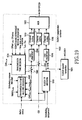
- FIG. 13 illustrates EU-DPCCH signaling for scheduling assignment between the UE and the Node B according to another embodiment of the present invention.
- T sch_int denotes a scheduling interval and each scheduling interval is divided into a buffer status information part and a CSI part.
- CNT sch_int denotes the index of a scheduling interval.
- T CSI and T buffer denote a CSI transmission interval and a transmission interval of buffer state information, respectively.
- the Node B generates scheduling assignment information based on the buffer status information and the CSI and transmits the scheduling assignment information in a time period 1314.
- An ROT is considered in determining the scheduling assignment information.
- the Node B estimates the amount of transmission packet data of the UE and, if the estimated data amount is less than THRES buffer , transmits a Scheduling Release message to the UE.
- the UE discontinues transmission of the buffer status information and CSI to the Node B.
- the amount of packet data queued in the EUDCH data buffer is THRES buffer ,the UE discontinues transmission of the buffer status information and CSI to the Node B.
- FIG. 14 is a block diagram illustrating an EUDCH transmission controller 1400 in the UE according to the second embodiment of the present invention.
- the components except a transmission start and end decider 1402 and a transmission time decider 1404, that is, an EUDCH TF decider 1416, CRC adders 1408 and 1418, channel encoders 1410, 1414, and 1420, a MUX 1422, and an EUDCH packet transmitter 1424, are identical in configuration and operation to their counterparts illustrated in FIG 9. Therefore, their description is not provided here and only the difference between the EUDCH transmission controller 1400 and the EUDCH transmission controller 900 will be described below.
- the transmission time decider 1404 determines the transmission time points of the buffer status information and the CSI after their first transmission time determined by the transmission start and end decider 1402. As described above with reference to FIG 13, the transmission time decider 1404 activates a buffer status switch 1406 and a CSI switch 1412 at the first transmission time of the buffer status information and the CSI. After transmitting the first CSI at the first transmission time point, the transmission time decider 1404 activates the CSI switch 1412 in scheduling intervals determined according to T CSI to periodically transmit the CSI.
- the transmission time decider 1404 when a new data arrival indication indicates generation of new data in the EUDCH data buffer, activates the buffer status switch 1406. That is, at the first buffer status transmission time after the new data arrival indication indicates generation of new data, the transmission time decider 1404 activates the buffer status switch 1406.
- the transmission time decider 1404 activates the buffer status switch 1406.
- the transmission time decider 1404 simultaneously activates the buffer status switch 1406 and the CSI switch 1412.
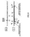
- FIG 15 is a flowchart illustrating the operation of the transmitter in the UE according to the second embodiment of the present invention.
- the UE monitors its buffer status, that is, the amount of data stored in the EUDCH data buffer in step 1500 and determines if the data amount is at least equal to THRES buffer in step 1502. If the data amount is at least equal to THRES buffer , the UE proceeds to step 1506. If the data amount is less than THRES buffer , the UE proceeds to step 1504. In step 1504, the UE waits until the next scheduling interval, and returns to step 1500 to monitor the EUDCH data buffer.
- step 1506 the UE initially transmits buffer status information and CSI to the Node B, waits until the next scheduling interval in step 1508, and monitors the EUDCH data buffer in step 1510.
- step 1512 the UE determines whether or not to continue transmitting the buffer status information and the CSI. The determination is made by comparing the amount of packet data stored in the EUDCH data buffer with THRES buffer , as described above. If the data amount is still at least equal to THRES buffer , the UE proceeds to step 1514 to continue transmitting the buffer status information and the CSI. If the data amount is less than THRES buffer, the UE proceeds to step 1528.
- step 1528 the UE determines whether to continue the EUDCH data service. If the UE determines to continue the EUDCH data service, it waits until the next scheduling interval in step 1530 and returns to step 1500. If the UE determines not to continue the EUDCH data service, it terminates the procedure.
- step 1514 the UE determines if the buffer status information is to be transmitted in the current scheduling interval according to T buffer . If the buffer status information is to be transmitted in the current scheduling interval, the UE proceeds to step 1516. If the buffer status information is not to be transmitted in the current scheduling interval, the UE proceeds to step 1524. In step 1524, the UE determines if new data has been generated in the EUDCH data buffer. Upon generation of the new data, the UE proceeds to step 1518; otherwise, it proceeds to step 1520.
- step 1520 the UE determines if the buffer status information has been transmitted at the previous transmission time of the buffer status information. If the buffer status information has been transmitted at the previous transmission time, the UE proceeds to step 1522. If the buffer status information has not been transmitted at the previous transmission time, the UE proceeds to step 1524. In step 1522, the UE determines if scheduling assignment information has been received from the Node B after the previous transmission time point of the buffer status information. If the scheduling assignment information has been received, the UB proceeds to step 1524. If the scheduling assignment information has not been received, the UE transmits proceeds to step 1518.
- the UE transmits the buffer status information in step 1518. Although not depicted in step 1518 in FIG 15, if the previous buffer status information is the first buffer status information, the UE transmits both the buffer status information and the CSI in step 1518.
- step 1524 the UE determines whether the current scheduling interval is a transmission time point of the CSI according to T CSI that the RNC notified the UE of. If the CSI is supposed to be transmitted in the current scheduling index, the UE transmits the CSI in step 1526 and returns to step 1508. However, if the CSI is not supposed to be transmitted in the current scheduling interval, the UE returns to step 1508.
- FIG. 16 is a block diagram illustrating a receiver in the Node B for receiving. the buffer status information and CSI according to the second embodiment of the present invention.
- an antenna 1600 receives an RF signal from the UE.
- An RF processor 1602 down converts the RF signal to a baseband signal.
- a pulse shaping filter 1604 converts the baseband signal to a digital signal.
- a descrambler 1606 descrambles the digital signal with a scrambling code C scramble .
- the descrambled signal is multiplied by an OVSF code C OVSP in a despreader 1608 and transmitted to a DEMUX 1612 through a channel compensator 1610.
- the DEMUX 1612 demultiplexes a signal received from the channel compensator 1610 into coded buffer status information, CSI, and E-TFRI. Because a CSI switch 1618 and a buffer status switch 1634 are activated at a first time, the coded buffer status information and the coded CSI are provided to a buffer status channel decoder 1622 and a CSI channel decoder 1620, respectively.
- the buffer status channel decoder 1622 decodes the coded buffer status information.
- a buffer status CRC checker 1624 checks a CRC of the decoded buffer status information and provides a CRC check result to a reception time controller 1632. Using the CRC check result, the reception time controller 1632 determines if the buffer status information has been received from the UE. If the CRC check result is good, which implies that the buffer status information has been received from the UE, the reception time controller 1632 determines that it is the first reception time of the CSI and activates the CSI switch 1618. Upon receipt of the first buffer status information, the reception time controller 1632 determines CSI reception time points using CNT sch_int and T CSI , and activates the CSI switch 1618 in scheduling intervals corresponding to the CSI reception time points.
- the reception time controller 1632 determines reception times of the buffer status information using CNT sch_int , and T buffer , and activates the buffer status switch 1634 in scheduling intervals corresponding to the reception times of the buffer status information. Accordingly, the buffer status information is not always received at the determined reception times. That is, if new data is not generated in the data buffer of the UE and the Node B transmits scheduling assignment information to the UE within the latest transmission interval of the buffer status information, the buffer status information is not received at its reception times.
- the CSI channel decoder 1620 channel-decodes the coded CSI.
- An EUDCH scheduler 1628 generates scheduling assignment information using the CSI received from the CSI channel decoder 1620 and the buffer status information received from the buffer status CRC checker 1624.
- An E-TFRI channel decoder 1614 channel-decodes the coded E-TFRI received from the DEMUX 1612.
- An E-TFRI CRC checker 1616 checks a CRC of the E-TFRI. If the CRC check result is good, the E-TFRI is provided to an EUDCH data decoder 1626.
- the EUDCH data decoder 1626 decodes EUDCH data received on the EU-DPDCH from the UE using the E-TFRI.
- a UE buffer status estimator 1630 estimates the buffer status of the UE using the buffer status information received from the buffer status CRC checker 1624 and the E-TFRI received from the E-TFRI CRC checker 1616. The buffer status estimate is provided to the reception time controller 1632. If the buffer status estimate is less than THRES buffer , the reception time controller 1632 concludes that it is time to terminate the reception of the buffer status information and the CSI and controls the EU-SCHCCH transmitter illustrated in FIG. 5B to transmit a Scheduling Release message to the UE.
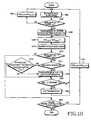
- FIG. 17 is a flowchart illustrating an operation for receiving buffer status information and CSI in the Node B according to the second embodiment of the present invention.
- the Node B channel-decodes coded buffer status information received from the UE in step 1700 and CRC-checks the decoded buffer status information in step 1702. Using the CRC check result, the Node B determines if the UE has transmitted the buffer status information in the current scheduling interval in step 1704. If the CRC check is passed, the buffer status information is provided to the EUDCH scheduler and the Node B proceeds to step 1706. If the CRC check is failed, the Node B waits until the next scheduling interval in step 1708 and returns to step 1700.
- step 1706 the Node B channel-decodes coded CSI following the buffer status information, provides the decoded CSI to the EUDCH scheduler and in step 1710, and waits until the next scheduling interval.
- step 1712 the Node B estimates the buffer status of the UE using the last received buffer status information and the amount of received data.
- the received data amount is known from the E-TFRI and the buffer status is estimated by subtracting the received data amount from the last received buffer status information.
- step 1714 the Node B determines if the buffer status estimate is at least equal to THRES buffer . If the buffer status estimate is at least equal to THRES buffer , the Node B proceeds to step 1716. However, if the buffer status estimate is less than THRES buffer, the Node B transmits a Scheduling Release message to the UE in step 1718 and proceeds to step 1720. Step 1718 is optional depending on system implementation.
- step 1720 the Node B determines whether or not to continue the EUDCH data service. If the Node B determines to continue the EUDCH data service, it waits until the next scheduling interval in step 1722 and returns to step 1700. However, if the Node B determines not to continue the EUDCH data service, it terminates the procedure.
- step 1716 the Node B determines if the buffer status information is supposed to be received in the current scheduling interval according to its reception interval received from the RNC. If the buffer status information is supposed to be received in the current scheduling interval, the Node B proceeds to step 1724. If the buffer status information is not supposed to be received in the current scheduling interval, the Node B proceeds to step 1728.
- the Node B receives coded buffer status information in the current scheduling interval, channel-decodes it in step 1724, and checks the CRC of the decoded buffer status information in step 1726. If the CRC check is passed, the buffer status information is provided to the EUDCH scheduler.
- the Node B determines if the CSI is supposed to be received in the current scheduling interval according to its reception interval received from the RNC. If the CSI is supposed to be received in the current scheduling interval, the Node B receives coded CSI in the current scheduling interval, channel-decodes it in step 1730, and returns to step 1710. If the CSI is not supposed to be received in the current scheduling interval, the Node B returns to step 1710. The decoded CSI is provided to the EUDCH scheduler.
- the RNC controls the transmission times of buffer status information and CSI for a plurality of UEs in order to prevent the increase of the uplink interference caused by uplink signaling.
- the RNC controls the UEs to transmit buffer status information and CSI in different scheduling intervals.
- Each UE transmits the buffer status information to the Node B in scheduling intervals satisfying Equation (3) according to its offset buffer .
- offset CSI is an integer specific to each UE to prevent the UEs from transmitting CSIs at the same time and thus increasing the measured ROT of the Node B.
- Each UE transmits the CSI to the Node B in scheduling intervals satisfying Equation (4) according to its offset CSI .
- offset buffer and offset CSI can be identical or different.
- the UE transmits the buffer status information only at a transmission time determined by Equation (3) even if the amount of packet data queued in its EUDCH data buffer is at least equal to a predetermined threshold. Also, the Node B checks if the buffer status information has been received only at a reception time determined by Equation (3), thereby enabling limited radio resources of the Node B to be shared among a plurality of UEs.
- FIG 18 illustrates EU-DPCCH signaling for scheduling assignment between the Node B and the UE according to the third embodiment of the present invention.
- the UE has offset buffer set to 0 and offset CSI set to 0.
- T buffer is six times T sch_int
- T CSI is four times T sch-int .
- the Node B In a time period 1816, the Node B generates scheduling assignment information based on the buffer status information and CSI received in the scheduling interval 1802 and transmits the scheduling assignment information to the UE. Accordingly, upon receipt of the buffer status information from the UE, the Node B always transmits the scheduling assignment information to the UE within T buffer .
- the Node B estimates the amount of transmission packet data of the UE and, if the estimated data amount is less than THRES buffer , transmits a Scheduling Release message to the UE.
- the UE discontinues transmission of the buffer status information and CSI to the Node B.
- the amount of packet data queued in the EUDCH data buffer is THRES buffer , the UE discontinues transmission of the buffer status information and CSI to the Node B.
- FIG 19 is a block diagram illustrating an EUDCH transmission controller 1900 in the UE according to the third embodiment of the present invention.
- the components in FIG 19, except a transmission start and end decider 1902 and a transmission time decider 1904, i.e., an EUDCH TF decider 1916, CRC adders 1908 and 1918, channel encoders 1910, 1914, and 1920, a MUX 1922, and an EUDCH packet transmitter 1924, are identical in configuration and operation to their counterparts illustrated in FIG 9. Therefore, their description is not provided here and only the difference between the EUDCH transmission controller 1900 and the EUDCH transmission controller 900 will be described below.
- the transmission start and end decider 1902 determines the transmission start and end times of the buffer status information and the CSI.
- the transmission start is determined in consideration of the status of the EUDCH data buffer, T buffer , offset buffer , and THRES buffer .
- the transmission of the buffer status information starts at the first of times set for the buffer status information after the buffer status information is at least equal to THRES buffer ⁇
- the CSI is initially transmitted together with the first buffer status information.
- a Scheduling Release message is received from the Node B, the transmission of the buffer status information and the CSI is terminated. However, if the buffer status information is less than THRES buffer , the transmission of the buffer status information and the CSI is terminated.
- the transmission time decider 1904 determines the transmission times of the buffer status information and CSI after the transmission start decided by the transmission start and end decider 1902, as illustrated in FIG 18.
- the transmission time decider 1904 activates a buffer status switch 1906 and a CSI switch 1912 at the first transmission time of the buffer status information and the CSI.
- the transmission time decider 1904 activates the CSI switch 1912 in scheduling intervals determined according to CNT sch_int , T CSI , and Offset CSI , to periodically transmit the CSI.
- the transmission time decider 1904 activates the buffer status switch 1906 to transmit the buffer status information.
- the transmission times of the buffer status information are determined according to CNT sch_int, T buffer , and Offset buffer .
- the transmission time decider 1904 controls the buffer status switch 1906 and the CSI switch 1912 according to a scheduling assignment receive indicator and T buffer .
- the scheduling assignment receive indicator does not indicate reception of scheduling assignment information within T buffer
- the transmission time decider 1904 activates the buffer status switch 1906 at the next transmission time of the buffer status information.
- the scheduling assignment receive indicator does not indicate reception of scheduling assignment information within T buffer
- the transmission time decider 1904 simultaneously activates the buffer status switch 1906 and the CSI switch 1912.
- FIG 20 is a flowchart illustrating an operation of the transmitter in the UE according to the third embodiment of the present invention.
- the UE determines if the current scheduling interval is a transmission time for buffer status information decided by Equation (3) in step 2000. If the current scheduling interval is a transmission time for buffer status information, the UE proceeds to step 2002. If the current scheduling interval is not a transmission time for buffer status information, the UE proceeds to step 2004.
- the UE monitors its buffer status, that is, the amount of data stored in the EUDCH data buffer in step 2002 and determines if the data amount is at least equal to THRES buffer in step 2006. If the data amount is at least equal to THRES buffer , the UE proceeds to step 2008. If the data amount is less than THRES buffer , the UE proceeds to step 2004. In step 2004, the UE waits until the next scheduling interval, and returns to step 2000 to monitor the EUDCH data buffer.
- step 2008 the UE initially transmits the buffer status information and CSI to the Node B, waits until the next scheduling interval in step 2010, and monitors the EUDCH data buffer in step 2012.
- step 2014 the UE determines whether or not to continue transmitting the buffer status information and the CSI. The determination is made by comparing the amount of packet data stored in the EUDCH data buffer with THRES buffer , as described above. If the data amount is still at least equal to THRES buffer , the UE proceeds to step 2016 to continue transmitting the buffer status information and the CSI. If the data amount is less than THRES buffer , the UE proceeds to step 2018.
- step 2018 the UE determines whether or not to continue the EUDCH data service. If the UE determines to continue the EUDCH data service, it waits until the next scheduling interval in step 2020 and returns to step 2000. If the UE determines not to continue the EUDCH data service, it terminates the procedure.
- step 2016, the UE determines if the buffer status information is to be transmitted in the current scheduling interval. If the buffer status information is to be transmitted in the current scheduling interval, the UE proceeds to step 2022. If the buffer status information is not to be transmitted in the current scheduling interval, the UE proceeds to step 2030.
- step 2022 the UE determines if new data has been generated in the EUDCH data buffer. Upon generation of the new data, the UE proceeds to step 2028; otherwise, it proceeds to step 2024.
- step 2024 the UE determines if the buffer status information has been transmitted at the previous transmission time of the buffer status information. If the buffer status information has been transmitted at the previous transmission time, the UE proceeds to step 2026. If the buffer status information has not been transmitted at the previous transmission time, the UE proceeds to step 2030.
- step 2026 the UE determines if scheduling assignment information has been received from the Node B after the previous transmission time point of the buffer status information. If the scheduling assignment information has been received, the UE proceeds to step 2030. If the scheduling assignment information has not been received, the UE proceeds to step 2028.
- the UE transmits the buffer status information in step 2028. Although not depicted in step 2028 in FIG 20, if the previous buffer status information is the first buffer status information, the UE transmits both the buffer status information and the CSI in step 2028.
- step 2030 the UE determines if the current scheduling interval is a transmission time point of the CSI according to T CSI that the RNC notified the UE of. If the CSI is supposed to be transmitted in the current scheduling index, the UE transmits the CSI in step 2032 and returns to step 2010. However, if the CSI is not supposed to be transmitted in the current scheduling interval, the UE returns to step 2010.
- FIG. 21 is a block diagram illustrating a receiver in the Node B for receiving the buffer status information and CSI according to the third embodiment of the present invention.
- an antenna 2100 receives an RF signal from the UE.
- An RF processor 2102 downconverts the RF signal to a baseband signal.
- a pulse shaping filter 2104 converts the baseband signal to a digital signal.
- a descrambler 2106 descrambles the digital signal with a scrambling code C sramble ⁇ The descrambled signal is multiplied by an OVSF code C OVSF in a despreader 2108 and transmitted to a DEMUX 2112 through a channel compensator 2110.
- the DEMUX 2112 demultiplexes a signal received from the channel compensator 2110 into coded buffer status information, CSI, and E-TFRI. Because a CSI switch 2118 and a buffer status switch 2134 are activated at a first time, the coded buffer status information and the coded CSI are provided to a buffer status channel decoder 2122 and a CSI channel decoder 2120, respectively.
- the buffer status channel decoder 2122 decodes the coded buffer status information.
- a buffer status CRC checker 2124 checks a CRC of the decoded buffer status information and provides a CRC check result to a reception time controller 2132. Using the CRC check result, the reception time controller 2132 determines if the buffer status information has been received from the UE. If the CRC check result is good, which implies that the buffer status information has been received from the UE, the reception time controller 2132 activates the CSI switch 2118.
- the reception time controller 2132 determines reception times of the CSI using CNT sch_int , offset CSI , and T CSI and activates the CSI switch 2118 in scheduling intervals corresponding to the reception times of the CSI.
- reception time controller 2132 determines reception times of the buffer status information using CNT sch_int , offset buffer , and T buffer and activates the buffer status switch 2134 in scheduling intervals corresponding to the reception times of the buffer status information.
- the buffer status information is not always received at the determined reception time points. That is, if new data is not generated in the data buffer of the UE and the Node B transmits scheduling assignment information to the UE within the latest transmission interval of the buffer status information, the buffer status information is not received at its reception times.
- the CSI channel decoder 2120 channel-decodes the coded CSI.
- An EUDCH scheduler 2128 generates scheduling assignment information using the CSI received from the CSI channel decoder 2120 and the buffer status information received from the buffer status CRC checker 2124.
- An E-TFRI channel decoder 2114 channel-decodes the coded E-TFRI received from the DEMUX 2112.
- An E-TFRI CRC checker 2116 checks a CRC of the E-TFRI. If the CRC check result is good, the E-TFRI is provided to an EUDCH data decoder 2126.
- the EUDCH data decoder 2126 decodes EUDCH data received on the EU-DPDCH from the UE using the E-TFRI.
- a UE buffer status estimator 2130 estimates the buffer status of the UE using the buffer status information received from the buffer status CRC checker 2124 and the E-TFRI received from the E-TFRI CRC checker 2116. The buffer status estimate is provided to the reception time controller 2132. If the buffer status estimate is less than THRES buffer , the reception time controller 2132 concludes that it is time to terminate the reception of the buffer status information and the CSI and controls the EU-SCHCCH transmitter illustrated in FIG. 5B to transmit a Scheduling Release message to the UE.
- FIG. 22 is a flowchart illustrating an operation for receiving buffer status information and CSI in the Node B according to the third embodiment of the present invention.
- the Node B determines if the buffer status information is supposed to be received in the current scheduling interval in step 2200. If the buffer status information is supposed to be received in the current scheduling interval, the Node B proceeds to step 2202. If the buffer status information is not supposed to be received in the current scheduling interval, the UE proceeds to step 2204.
- the Node B channel-decodes coded buffer status information received from the UE in step 2202 and CRC-checks the decoded buffer status information in step 2206.
- the Node B determines if the UE has transmitted the buffer status information in the current scheduling interval in step 2208. If the CRC check is passed, the buffer status information is provided to the EUDCH scheduler and the Node B proceeds to step 2210. If the CRC check is failed, the Node B waits until the next scheduling interval in step 2204 and returns to step 2200.
- step 2210 the Node B channel-decodes coded CSI following the buffer status information and provides the decoded CSI to the EUDCH scheduler.
- step 2212 the Node B waits until the next scheduling interval.
- the Node B estimates the buffer status of the UE using the last received buffer status information and the amount of received data.
- the received data amount is known from the E-TFRI and the buffer status is estimated by subtracting the received data amount from the last received buffer status information.
- the Node B determines if the buffer status estimate is at least equal to THRES buffer . If the buffer status estimate is at least equal to THRES buffer , the Node B proceeds to step 2218. However, if the buffer status estimate is less than THRES buffer , the Node B transmits a Scheduling Release message to the UE in step 2220 and proceeds to step 2222.
- step 2220 is optional depending on system implementation.
- the Node B determines whether or not to continue the EUDCH data service. If the Node B determines to continue the EUDCH data service, it waits until the next scheduling interval in step 2224 and returns to step 2200. However, if the Node B determines not to continue the EUDCH data service, it terminates the procedure.
- step 2218 the Node B determines if the buffer status information is supposed to be received in the current scheduling interval according to Equation (3). If the buffer status information is supposed to be received in the current scheduling interval, the Node B proceeds to step 2226. If the buffer status information is not supposed to be received in the current scheduling interval, the Node B proceeds to step 2230.
- the Node B receives coded buffer status information in the current scheduling interval, channel-decodes it in step 2226, and checks the CRC of the decoded buffer status information in step 2228. If the CRC check is passed, the buffer status information is provided to the EUDCH scheduler. In step 2230, the Node B determines if the CSI is supposed to be received in the current scheduling interval according to Equation (3).
- the Node B receives coded CSI in the current scheduling interval and channel-decodes it in step 2232 and returns to step 2212. If the CSI is not supposed to be received in the current scheduling interval, the Node B returns to step 2212.
- the decoded CSI is provided to the EUDCH scheduler.
- FIG 23 illustrates transmission of buffer status information and CSI according to a fourth embodiment of the present invention.
- the CSI is transmitted at CSI transmission times determined according to a predetermined CSI transmission interval.
- the buffer status information is transmitted periodically at its transmission time points and also when new data is generated in the EUDCH data buffer of the UE.
- T buffer is eight times T sch_int
- the UE transmits the buffer status information. Therefore, a time delay involved in estimating the UE buffer status in the Node B can be reduced.
- the Node B transmits scheduling assignment information in time periods 2314 and 2316 based on the received buffer status information and CSI. In a time period 2318, the Node B transmits a Scheduling Release message to the UE, determining that no data remains in the EUDCH data buffer of the UE.
- An EUDCH transmission controller for transmitting the buffer status information and the CSI according to the fourth embodiment of the present invention is configured as illustrated in FIG 14, except that the transmission time decider 1404 controls the CSI switch 1412 to transmit the CSI periodically at predetermined times and controls the buffer status switch 1406 to periodically transmit the buffer status information and upon generation of new packet data.
- FIG 24 is a flowchart illustrates an operation of the transmitter in the UE according to the fourth embodiment of the present invention.
- the UE monitors its buffer status, that is, the amount of data stored in the EUDCH data buffer in step 2400 and determines if the data amount is at least equal to THRES buffer in step 2402. If the data amount is at least equal to THRES buffer , the UE proceeds to step 2406. If the data amount is less than THRES buffer , the UE proceeds to step 2404. In step 2404, the UE waits until the next scheduling interval, and returns to step 2400 to monitor the EUDCH data buffer.
- step 2406 the UE initially transmits buffer status information and CSI to the Node B, waits until the next scheduling interval in step 2408, and monitors the EUDCH data buffer in step 2410.
- step 2412 the UE determines whether or not to continue transmitting the buffer status information and the CSI. The determination is made by comparing the amount of packet data stored in the EUDCH data buffer with THRES buffer . as described above. If the data amount is still at least equal to THRES buffer , the UE proceeds to step 2414 to continue transmitting the buffer status information and the CSI. If the data amount is less than THRES buffer , the UE proceeds to step 2424.
- step 2424 the UE determines whether or not to continue the EUDCH data service. If the UE determines to continue the EUDCH data service, it waits until the next scheduling interval in step 2426 and returns to step 2400. If the UE determines not to continue the EUDCH data service, it terminates the procedure.
- step 2414 the UE determines if new data has been generated in the EUDCH data buffer. Upon generation of new data, the UE proceeds to step 2416; otherwise, it proceeds to step 2418.
- step 2418 the Node B determines if the buffer status information is to be transmitted in the current scheduling interval according to T buffer that the RNC notified the UE of. If the buffer status information is to be transmitted in the current scheduling interval, the UE proceeds to step 2416. If the buffer status information is not to be transmitted in the current scheduling interval, the UE proceeds to step 2420. In step 2416, the UE transmits the buffer status information.
- step 2420 the UE determines if the current scheduling interval is a transmission time of the CSI according to T CSI that the RNC notified the UE of. If the CSI is supposed to be transmitted in the current scheduling index, the UE transmits the CSI in step 2422 and returns to step 2408. However, if the CSI is not supposed to be transmitted in the current scheduling interval, the UE returns to step 2408. Although not depicted in FIG. 24, if the UE fails to receive the scheduling assignment information from the Node B within T buffer , after transmission of the first buffer status information in step 2406, it simultaneously transmits the buffer status information and the CSI to the Node B.
- FIG. 25 illustrates transmission of buffer status information using a timer according to a fifth embodiment of the present invention.
- the use of the timer in determining transmission times for the buffer status information in the UE reduces a time delay in estimating the buffer status of the UE in the Node B and additional uplink interference caused by transmission of the buffer status information.
- the CSI is periodically transmitted such that CSI transmission times for a plurality of UEs implementing the EUDCH service are distributed. As a result, the increase of uplink interference caused by the CSI transmission is minimized.
- the UE sets a timer provided for transmission of the buffer status information to T buffer and activates the timer.
- the value of the timer is decremented by 1 as each scheduling interval passes.
- the UE transmits the buffer status information.
- the Node B transmits scheduling assignment information in a time period 2516 based on the buffer status information and CSI received in the scheduling interval 2500 and in a time period 2518 based on the buffer status information and CSI received in the scheduling intervals 2512 and 2514. In a time period 2520, the Node B transmits a Scheduling Release message to the UE, determining that no data remains in the EUDCH data buffer of the UE.
- An EUDCH transmission controller for transmitting the buffer status information and the CSI according to the fifth embodiment of the present invention is configured as illustrated in FIG. 14, except that the transmission time decider 1404 controls the CSI switch 1412 to periodically transmit the CSI at predetermined times and controls the buffer status switch 1406 to periodically transmit the buffer status information using a timer set to T buffer or from a timeafter generation of new packet data.
- FIG. 26 is a flowchart illustrating an operation of the transmitter in the UE according to the fifth embodiment of the present invention.
- the UE monitors its buffer status, that is, the amount of data stored in the EUDCH data buffer in step 2600 and determines if the data amount is at least equal to THRES buffer in step 2602. If the data amount is at least equal to THRES buffer, the UE proceeds to step 2606. If the data amount is less than THRES buffer, the UE proceeds to step 2604. In step 2604, the UE waits until the next scheduling interval, and returns to step 2600 to monitor the EUDCH data buffer.
- step 2606 the UE initially transmits buffer status information and CSI to the Node B.
- the UE activates a timer set to T buffer in step 2608, waits until the next scheduling interval in step 2610, and monitors the EUDCH data buffer in step 2612.
- step 2614 the UE determines whether or not to continue transmitting the buffer status information and the CSI. As described above, the determination is made by comparing the amount of packet data stored in the EUDCH data buffer with THRES buffer . If the data amount is still at least equal to THRES buffer, the UE proceeds to step 2616 to continue transmitting the buffer status information and the CSI. If the data amount is less than THRES buffer , the UE proceeds to step 2630.
- step 2630 the UE determines whether or not to continue the EUDCH data service. If the UE determines to continue the EUDCH data service, it waits until the next scheduling interval in step 2632 and returns to step 2600. If the UE determines not to continue the EUDCH data service, it terminates the procedure.
- the UE decrements the value of the timer by 1 in step 2616 and determines if new data has been generated in the EUDCH data buffer in step 2618. Upon generation of new data, the UE proceeds to step 2622; otherwise, it proceeds to step 2620. In step 2620, the UE determines if the timer value is 0. Upon time expiration, the UE proceeds to step 2622. If the timer is not expired, the UE proceeds to step 2626.
- the UE After transmitting the buffer status information in step 2622, the UE reactivates the timer in step 2624.
- the Node B determines if the current scheduling interval is a transmission time of the CSI according to T CSI that the RNC notified the UE of. If the CSI is supposed to be transmitted in the current scheduling index, the UE transmits the CSI in step 2628 and returns to step 2610. However, if the CSI is not supposed to be transmitted in the current scheduling interval, the UE returns to step 2610.
- the UE fails to receive the scheduling assignment information from the Node B within T buffer , after transmission of the first buffer status information in step 2606, it simultaneously transmits the buffer status information and the CSI to the Node B.
- Periodic CSI transmission irrespective of the transmission times of buffer status information, is common to the first through fifth embodiments of the present invention.
- Node B controlled scheduling can be performed taking into account long-term fading such as topographical features-incurred shadowing, that is, an average channel change over a long term. In this case, the average channel state over a long term is reflected in the CSI.
- T CSI can be set to be longer than T buffer .
- FIG. 27 illustrates a code block having buffer status information and CSI transmitted at a transmission time point of the buffer status information from a UE according to a sixth embodiment of the present invention.
- the UE transmits both the buffer status information and the CSI at a transmission time. That is, after initially transmitting the buffer status information and the CSI, the UE simultaneously transmits them at transmission times of the buffer status information, which are determined according to T buffer , a presence or absence of new data, or T buffer and the presence or absence of new data. Therefore, a CRC attached to the code block is commonly applied to the buffer status information and the CSI.
- the UE attaches a common CRC to a data part including the buffer status information and the CSI in a code block and channel-encodes the code block prior to transmission.
- the Node B detects the common CRC and determines by a CRC check if the buffer status information and the CSI have been received normally.
- a UE transmits the buffer status information indicating the status of its EUDCH data buffer to a Node B, upon generation of a new data event in the EUDCH data buffer and/or at transmission time points set for the buffer status information. Therefore, the number of transmissions of the buffer status information from the UE and a time delay in estimating the buffer status of the UE in the Node B are reduced.
Landscapes
- Engineering & Computer Science (AREA)
- Computer Networks & Wireless Communication (AREA)
- Signal Processing (AREA)
- Databases & Information Systems (AREA)
- Mobile Radio Communication Systems (AREA)
- Small-Scale Networks (AREA)
Applications Claiming Priority (6)
| Application Number | Priority Date | Filing Date | Title |
|---|---|---|---|
| KR2003057733 | 2003-08-20 | ||
| KR20030057733 | 2003-08-20 | ||
| KR2003068505 | 2003-10-01 | ||
| KR20030068505 | 2003-10-01 | ||
| KR2003069740 | 2003-10-07 | ||
| KR1020030069740A KR100644996B1 (ko) | 2003-08-20 | 2003-10-07 | 이동통신 시스템에서 상향링크 패킷 전송을 위한 스케쥴링 할당 방법 및 장치 |
Publications (1)
| Publication Number | Publication Date |
|---|---|
| EP1509012A2 true EP1509012A2 (de) | 2005-02-23 |
Family
ID=34068944
Family Applications (1)
| Application Number | Title | Priority Date | Filing Date |
|---|---|---|---|
| EP20040019726 Withdrawn EP1509012A2 (de) | 2003-08-20 | 2004-08-19 | Verfahren und Vorrichtung zur Planung von Uplinkpaketübertragung in einem mobilen Kommunikationssystem |
Country Status (4)
| Country | Link |
|---|---|
| US (1) | US20050083943A1 (de) |
| EP (1) | EP1509012A2 (de) |
| JP (1) | JP2005094750A (de) |
| CN (1) | CN1302675C (de) |
Cited By (9)
| Publication number | Priority date | Publication date | Assignee | Title |
|---|---|---|---|---|
| WO2007021608A3 (en) * | 2005-08-15 | 2007-06-28 | Lucent Technologies Inc | Method for assigning uplink and/or downlink capacities based on available capacity |
| EP1883190A1 (de) * | 2006-07-28 | 2008-01-30 | Innovative Sonic Limited | Verfahren und Vorrichtung zur Einstellung von Felddaten über Terminplaninformation in einem drahtlosen Kommunikationssystem |
| WO2008156402A1 (en) | 2007-06-19 | 2008-12-24 | Telefonaktiebolaget Lm Ericsson (Publ) | Methods and systems for scheduling resources in a telecommunication system |
| WO2008115029A3 (en) * | 2007-03-21 | 2010-09-23 | Lg Electronics Inc. | Method of transmitting data in a wireless communication system |
| US8254323B2 (en) | 2007-03-16 | 2012-08-28 | Lg Electronics Inc. | Method of monitoring control channel in wireless communication system |
| EP2549821A1 (de) * | 2008-02-04 | 2013-01-23 | Huawei Technologies Co., Ltd. | Verfahren, Vorrichtung und System zum Auslösen einer Betriebsmittelverteilung |
| US8619682B2 (en) | 2006-08-23 | 2013-12-31 | Lg Electronics Inc. | Method for performing random access procedure in wireless communication system |
| US8743799B2 (en) | 2010-06-24 | 2014-06-03 | Nokia Siemens Networks Oy | Change of rate matching modes in presence of channel state information reference signal transmission |
| GB2516941A (en) * | 2013-08-07 | 2015-02-11 | Samsung Electronics Co Ltd | Scheduling Resources at a Relay Station in a Mobile Communications Network |
Families Citing this family (76)
| Publication number | Priority date | Publication date | Assignee | Title |
|---|---|---|---|---|
| US8570952B2 (en) | 2004-04-29 | 2013-10-29 | Interdigital Technology Corporation | Method and apparatus for selectively enabling reception of downlink signaling channels |
| EP1804534B1 (de) * | 2004-09-17 | 2014-04-23 | Ntt Docomo, Inc. | Basisstation die einen erweiterten dedizierten kanal benutzt |
| CN101044698A (zh) * | 2004-10-19 | 2007-09-26 | 三星电子株式会社 | 在移动通信系统中用信令方式发送用于上行链路数据传送的用户设备状态信息的方法和装置 |
| US20060233265A1 (en) * | 2005-04-15 | 2006-10-19 | Nokia Corporation | Joint feed-forward and feedback design for wireless communication systems |
| US20060262806A1 (en) * | 2005-05-19 | 2006-11-23 | Imed Bouazizi | System and method for data delivery |
| DE102005050587A1 (de) | 2005-10-21 | 2007-05-03 | Siemens Ag | Verfahren zum Weiterleiten von Signalisierungsdaten in einer Netzübergangseinheit und in einer Steuereinheit sowie zugehörige Einheiten |
| CN101300876B (zh) * | 2005-12-14 | 2011-12-14 | 三菱电机株式会社 | 调度方法、基站和终端 |
| KR100934656B1 (ko) * | 2006-02-06 | 2009-12-31 | 엘지전자 주식회사 | 다중 반송파 시스템에서의 무선 자원 할당 방법 |
| KR100996704B1 (ko) | 2006-11-06 | 2010-11-25 | 삼성전자주식회사 | 버퍼 크기 정보의 전송 방법 |
| CN101548485B (zh) | 2006-11-15 | 2012-12-05 | 三星电子株式会社 | 用于移动通信系统中缓冲器状态报告的方法和装置 |
| JP5113186B2 (ja) | 2006-12-07 | 2013-01-09 | エルジー エレクトロニクス インコーポレイティド | 無線通信システムにおけるデータ伝達方法 |
| US8797879B2 (en) * | 2006-12-07 | 2014-08-05 | Lg Electronics Inc. | Method of transmitting and receiving status report in a mobile communication system |
| KR101342365B1 (ko) * | 2006-12-07 | 2013-12-16 | 엘지전자 주식회사 | 무선 통신 시스템에서의 데이터 전달 방법 |
| KR100933161B1 (ko) * | 2006-12-11 | 2009-12-21 | 삼성전자주식회사 | 통신시스템의 업링크 스케줄링 방법 및 장치 |
| ES2688776T3 (es) | 2006-12-21 | 2018-11-06 | Telefonaktiebolaget Lm Ericsson (Publ) | Procedimiento y aparato de transmisión de símbolos de canal de control |
| CN101212765B (zh) * | 2006-12-29 | 2011-05-18 | 大唐移动通信设备有限公司 | 一种资源调度方法及系统 |
| WO2008084957A1 (en) * | 2007-01-08 | 2008-07-17 | Lg Electronics Inc. | Method for receiving common channel in wireless communication and terminal thereof |
| US8194559B2 (en) * | 2007-01-09 | 2012-06-05 | Lg Electronics Inc. | Method of controlling data retransmission in a wireless communication system |
| WO2008084986A2 (en) * | 2007-01-09 | 2008-07-17 | Lg Electronics Inc. | Method of transmitting and receiving scheduling information in a wireless communication system |
| US8347174B2 (en) * | 2007-01-09 | 2013-01-01 | Lg Electronics Inc. | Method of transmitting and receiving data in a wireless communication system including error detection code decoded using equipment identifiers and group identifiers |
| KR101211758B1 (ko) * | 2007-01-10 | 2012-12-12 | 엘지전자 주식회사 | 무선 통신 시스템의 블록 데이터 생성 방법 |
| CN101578783A (zh) * | 2007-01-10 | 2009-11-11 | Lg电子株式会社 | 用于在移动通信中构造数据格式的方法及其终端 |
| JPWO2008108143A1 (ja) | 2007-03-06 | 2010-06-10 | 株式会社エヌ・ティ・ティ・ドコモ | 移動局装置及び通信制御方法 |
| WO2008133449A1 (en) | 2007-04-27 | 2008-11-06 | Samsung Electronics Co., Ltd. | Method and apparatus for transmitting and receiving uplink channel sounding reference signals in a wireless communication system |
| KR101414962B1 (ko) * | 2007-04-27 | 2014-07-07 | 삼성전자주식회사 | 무선통신 시스템에서 상향링크 채널사운딩 레퍼런스 신호의송수신 방법 |
| KR101341515B1 (ko) * | 2007-06-18 | 2013-12-16 | 엘지전자 주식회사 | 무선 통신 시스템에서의 반복 전송 정보 갱신 방법 |
| KR101486352B1 (ko) | 2007-06-18 | 2015-01-26 | 엘지전자 주식회사 | 무선 통신 시스템의 단말에서의 상향링크 동기 상태 제어방법 |
| WO2008156346A2 (en) * | 2007-06-20 | 2008-12-24 | Lg Electronics Inc. | A method of transmitting data in mobile communication system |
| WO2008156314A2 (en) * | 2007-06-20 | 2008-12-24 | Lg Electronics Inc. | Effective system information reception method |
| KR20090016419A (ko) * | 2007-08-10 | 2009-02-13 | 엘지전자 주식회사 | 동적 무선자원 할당방법에서 harq를 제어하는 방법 |
| KR101479341B1 (ko) * | 2007-08-10 | 2015-01-05 | 엘지전자 주식회사 | Mbms 서비스를 제공하는 무선 통신 시스템에서효율적인 수신 방법 |
| GB2464427B (en) * | 2007-08-10 | 2012-04-04 | Lg Electronics Inc | Method of reporting measurement result in wireless communication system |
| KR101514841B1 (ko) * | 2007-08-10 | 2015-04-23 | 엘지전자 주식회사 | 효율적인 랜덤 액세스 재시도를 수행하는 방법 |
| KR101461965B1 (ko) | 2007-08-14 | 2014-11-14 | 엘지전자 주식회사 | 무선 통신 시스템의 특정 프로토콜 계층에서의 데이터 블록전송 및 처리 방법 |
| KR101461970B1 (ko) * | 2007-09-13 | 2014-11-14 | 엘지전자 주식회사 | 무선 통신 시스템에서의 폴링 과정 수행 방법 |
| KR100937432B1 (ko) * | 2007-09-13 | 2010-01-18 | 엘지전자 주식회사 | 무선 통신 시스템에서의 무선자원 할당 방법 |
| JP4950338B2 (ja) * | 2007-09-13 | 2012-06-13 | エルジー エレクトロニクス インコーポレイティド | 無線通信システムにおける無線リソース割当方法 |
| KR101435844B1 (ko) * | 2007-09-18 | 2014-08-29 | 엘지전자 주식회사 | 무선 통신 시스템에서의 데이터 블록 전송 방법 |
| KR101591824B1 (ko) | 2007-09-18 | 2016-02-04 | 엘지전자 주식회사 | 무선 통신 시스템에서의 폴링 과정 수행 방법 |
| KR101396062B1 (ko) * | 2007-09-18 | 2014-05-26 | 엘지전자 주식회사 | 헤더 지시자를 이용한 효율적인 데이터 블록 전송방법 |
| KR101513033B1 (ko) | 2007-09-18 | 2015-04-17 | 엘지전자 주식회사 | 다중 계층 구조에서 QoS를 보장하기 위한 방법 |
| KR101487557B1 (ko) * | 2007-10-23 | 2015-01-29 | 엘지전자 주식회사 | 공통제어채널의 데이터를 전송하는 방법 |
| KR101476202B1 (ko) * | 2008-01-08 | 2014-12-24 | 엘지전자 주식회사 | 주기적/비주기적 채널상태정보 송수신 방법 |
| KR101531914B1 (ko) * | 2008-01-28 | 2015-06-29 | 엘지전자 주식회사 | 단말 유발 채널상태정보 전송 방법 |
| JP4937155B2 (ja) * | 2008-02-08 | 2012-05-23 | 株式会社エヌ・ティ・ティ・ドコモ | 移動通信方法、移動通信システム及び無線基地局 |
| KR101163275B1 (ko) * | 2008-03-17 | 2012-07-05 | 엘지전자 주식회사 | Pdcp 상태 보고 전송 방법 |
| WO2009115971A1 (en) * | 2008-03-21 | 2009-09-24 | Koninklijke Philips Electronics N.V. | Method for communicating and radio station therefor |
| US8228855B2 (en) | 2008-03-24 | 2012-07-24 | Qualcomm Incorporated | Uplink power headroom definition for E-DCH in CELL—FACH |
| KR101588037B1 (ko) * | 2008-04-30 | 2016-02-12 | 코닌클리케 필립스 엔.브이. | 네트워크 및 그에 대한 무선국들에서 통신하는 방법 |
| CA2737793C (en) * | 2008-09-19 | 2015-12-22 | Research In Motion Limited | Detection time of semi-persistent scheduling activation/reconfiguration signaling |
| EP2371169B1 (de) | 2008-12-15 | 2019-09-25 | BlackBerry Limited | Ausrichtung von semi-persistierender zeitplanung und diskontinuierlichem empfang |
| CN101772174B (zh) * | 2009-01-04 | 2013-04-10 | 电信科学技术研究院 | 提高上行调度性能的方法及用户设备 |
| JP5330547B2 (ja) * | 2009-02-09 | 2013-10-30 | テレフオンアクチーボラゲット エル エム エリクソン(パブル) | 無線通信システムにおける方法および構成 |
| US20100271990A1 (en) * | 2009-04-24 | 2010-10-28 | Motorola, Inc. | Method and apparatus for triggering buffer status reports with packet discarding |
| US8588102B2 (en) | 2009-06-02 | 2013-11-19 | Panasonic Corporation | Wireless communication apparatus and wireless communication method |
| JP5597715B2 (ja) * | 2009-10-02 | 2014-10-01 | インターデイジタル パテント ホールディングス インコーポレイテッド | アップリンクにおいて多重アンテナ送信の送信電力制御を行うための方法および装置 |
| KR101605687B1 (ko) | 2010-04-12 | 2016-03-23 | 삼성전자주식회사 | 이동통신 시스템에서 단말의 버퍼 데이터 지연 추정 방법 및 장치 |
| US9042353B2 (en) | 2010-10-06 | 2015-05-26 | Blackbird Technology Holdings, Inc. | Method and apparatus for low-power, long-range networking |
| WO2012048118A2 (en) | 2010-10-06 | 2012-04-12 | Blackbird Technology Holdings, Inc. | Method and apparatus for adaptive searching of distributed datasets |
| US8718551B2 (en) | 2010-10-12 | 2014-05-06 | Blackbird Technology Holdings, Inc. | Method and apparatus for a multi-band, multi-mode smartcard |
| WO2012068227A1 (en) | 2010-11-16 | 2012-05-24 | Blackbird Technology Holdings, Inc. | Method and apparatus for interfacing with a smartcard |
| WO2012100145A1 (en) | 2011-01-21 | 2012-07-26 | Blackbird Technology Holdings, Inc. | Method and apparatus for memory management |
| WO2012112650A1 (en) | 2011-02-15 | 2012-08-23 | Blackbird Technology Holdings, Inc. | Method and apparatus for plug and play, networkable iso 18000-7 connectivity |
| US8885586B2 (en) | 2011-03-02 | 2014-11-11 | Blackbird Technology Holdings, Inc. | Method and apparatus for query-based congestion control |
| US8929961B2 (en) | 2011-07-15 | 2015-01-06 | Blackbird Technology Holdings, Inc. | Protective case for adding wireless functionality to a handheld electronic device |
| CN104012011B (zh) * | 2011-11-04 | 2018-11-13 | 英特尔公司 | 用于下行链路多点协作通信的配置的信令 |
| WO2014003327A1 (en) | 2012-06-26 | 2014-01-03 | Lg Electronics Inc. | Method and apparatus for cancelling buffer status report in wireless communication system |
| JP2015528653A (ja) * | 2012-08-22 | 2015-09-28 | ノキア ソリューションズ アンド ネットワークス オサケユキチュア | 送信パラメータの判断 |
| US9036497B2 (en) * | 2013-01-07 | 2015-05-19 | Snu R&Db Foundation | Mobile video streaming enhancement in a network coding-capable wireless network |
| WO2015016550A1 (en) * | 2013-07-29 | 2015-02-05 | Lg Electronics Inc. | Method for calculating and reporting a buffer status and device therefor |
| US9954771B1 (en) * | 2015-01-30 | 2018-04-24 | Marvell Israel (M.I.S.L) Ltd. | Packet distribution with prefetch in a parallel processing network device |
| KR102186397B1 (ko) * | 2016-09-23 | 2020-12-04 | 주식회사 케이티 | 짧은 전송 시간 간격의 프레임 구조에서 채널 상태 정보를 전송하는 방법 및 장치 |
| CN109257245B (zh) * | 2017-07-14 | 2022-04-29 | 阿里巴巴集团控股有限公司 | 流量监测、上传控制的方法及设备 |
| JP6768625B2 (ja) * | 2017-11-17 | 2020-10-14 | 株式会社東芝 | 情報処理装置、情報処理方法、およびプログラム |
| CN109391929B (zh) * | 2018-11-23 | 2022-02-22 | 深圳时空壶技术有限公司 | 低功耗蓝牙数据传输方法及电子设备 |
| US11395221B2 (en) * | 2019-11-13 | 2022-07-19 | Schlage Lock Company Llc | Wireless device power optimization utilizing artificial intelligence and/or machine learning |
Family Cites Families (10)
| Publication number | Priority date | Publication date | Assignee | Title |
|---|---|---|---|---|
| FI112842B (fi) * | 1999-01-11 | 2004-01-15 | Nokia Corp | Menetelmä ja laitteet jatketun pakettikytkentäisen radioyhteyden toteuttamiseksi |
| KR100383572B1 (ko) * | 2000-06-28 | 2003-05-14 | 삼성전자주식회사 | 이동통신 시스템에서 역방향 데이터 전송 방법 및 그 장치 |
| US6819930B1 (en) * | 2000-11-03 | 2004-11-16 | Lucent Technologies Inc. | Apparatus and method for use in allocating a channel resource in wireless multiple access communications systems |
| US8111689B2 (en) * | 2001-01-16 | 2012-02-07 | Nokia Corporation | System for uplink scheduling packet based data traffic in wireless system |
| US7042856B2 (en) * | 2001-05-03 | 2006-05-09 | Qualcomm, Incorporation | Method and apparatus for controlling uplink transmissions of a wireless communication system |
| ATE258739T1 (de) * | 2001-05-25 | 2004-02-15 | Cit Alcatel | Verfahren zum zuweisen von übertragungsressourcen der aufwärtsrichtung eines drahtlosen kommunikationsnetzes und entsprechendes funkendgerät |
| JP3588064B2 (ja) * | 2001-07-13 | 2004-11-10 | 松下電器産業株式会社 | 送信装置および受信装置 |
| US8107885B2 (en) * | 2002-10-30 | 2012-01-31 | Motorola Mobility, Inc. | Method and apparatus for providing a distributed architecture digital wireless communication system |
| US8111668B2 (en) * | 2003-02-14 | 2012-02-07 | Alcatel Lucent | Signaling methods for wireless communication systems |
| US7640373B2 (en) * | 2003-04-25 | 2009-12-29 | Motorola, Inc. | Method and apparatus for channel quality feedback within a communication system |
-
2004
- 2004-08-19 EP EP20040019726 patent/EP1509012A2/de not_active Withdrawn
- 2004-08-20 CN CNB2004100959630A patent/CN1302675C/zh not_active Expired - Fee Related
- 2004-08-20 US US10/922,404 patent/US20050083943A1/en not_active Abandoned
- 2004-08-20 JP JP2004241636A patent/JP2005094750A/ja not_active Ceased
Cited By (36)
| Publication number | Priority date | Publication date | Assignee | Title |
|---|---|---|---|---|
| US7653396B2 (en) | 2005-08-15 | 2010-01-26 | Alcatel-Lucent Usa Inc. | Method for assigning uplink and/or downlink capacities based on available capacity |
| WO2007021608A3 (en) * | 2005-08-15 | 2007-06-28 | Lucent Technologies Inc | Method for assigning uplink and/or downlink capacities based on available capacity |
| JP2009505574A (ja) * | 2005-08-15 | 2009-02-05 | ルーセント テクノロジーズ インコーポレーテッド | 利用可能な容量に基づいてアップリンク及び/又はダウンリンクの容量を割り当てるための方法 |
| EP1883190A1 (de) * | 2006-07-28 | 2008-01-30 | Innovative Sonic Limited | Verfahren und Vorrichtung zur Einstellung von Felddaten über Terminplaninformation in einem drahtlosen Kommunikationssystem |
| KR100892658B1 (ko) | 2006-07-28 | 2009-04-15 | 이노베이티브 소닉 리미티드 | 무선통신시스템에서 스케쥴링 정보를 설정하는 방법 및장치 |
| US9894684B2 (en) | 2006-08-23 | 2018-02-13 | Lg Electronics Inc. | Method for performing random access procedure in wireless communication system |
| US9661662B2 (en) | 2006-08-23 | 2017-05-23 | Lg Electronics Inc. | Method for performing random access procedure in wireless communication system |
| US8619682B2 (en) | 2006-08-23 | 2013-12-31 | Lg Electronics Inc. | Method for performing random access procedure in wireless communication system |
| US9480085B2 (en) | 2006-08-23 | 2016-10-25 | Lg Electronics Inc. | Method for performing random access procedure in wireless communication system |
| US9131493B2 (en) | 2006-08-23 | 2015-09-08 | Lg Electronics Inc. | Method for performing random access procedure in wireless communication system |
| US9072051B2 (en) | 2007-03-16 | 2015-06-30 | Lg Electronics Inc. | Method of monitoring control channel in wireless communication system |
| US8254323B2 (en) | 2007-03-16 | 2012-08-28 | Lg Electronics Inc. | Method of monitoring control channel in wireless communication system |
| US8797904B2 (en) | 2007-03-16 | 2014-08-05 | Lg Electronics Inc. | Method of monitoring control channel in wireless communication system |
| US9326245B2 (en) | 2007-03-16 | 2016-04-26 | Lg Electronics Inc. | Method of monitoring control channel in wireless communication system |
| US8289911B2 (en) | 2007-03-21 | 2012-10-16 | Lg Electronics Inc. | Method of scheduling of transmitting data in a wireless communication system |
| WO2008115029A3 (en) * | 2007-03-21 | 2010-09-23 | Lg Electronics Inc. | Method of transmitting data in a wireless communication system |
| WO2008156402A1 (en) | 2007-06-19 | 2008-12-24 | Telefonaktiebolaget Lm Ericsson (Publ) | Methods and systems for scheduling resources in a telecommunication system |
| EP2158773A4 (de) * | 2007-06-19 | 2017-01-04 | Optis Cellular Technology, LLC | Verfahren und systeme zum einteilen von betriebsmitteln in ein telekommunikationssystem |
| US11160093B2 (en) | 2007-06-19 | 2021-10-26 | Optis Cellular Technology, Llc | Methods and systems for scheduling resources in a telecommunication system |
| US10721745B2 (en) | 2007-06-19 | 2020-07-21 | Optis Cellular Technology, Llc | Methods and systems for scheduling resources in a telecommunication system |
| RU2706024C2 (ru) * | 2007-06-19 | 2019-11-13 | ОПТИС СЕЛЛЬЮЛАР ТЕКНОЛОДЖИ, ЭлЭлСи | Способы и системы для планирования ресурсов в телекоммуникационной системе |
| CN105813219B (zh) * | 2007-06-19 | 2019-06-28 | 奥普蒂斯蜂窝技术有限责任公司 | 电信系统中调度资源的方法和系统 |
| EP3474592A1 (de) * | 2007-06-19 | 2019-04-24 | Optis Cellular Technology, LLC | Verfahren und systeme zur planung von ressourcen in einem telekommunikationssystem |
| CN105813219A (zh) * | 2007-06-19 | 2016-07-27 | 奥普蒂斯蜂窝技术有限责任公司 | 电信系统中调度资源的方法和系统 |
| US10098133B2 (en) | 2007-06-19 | 2018-10-09 | Optis Cellular Technology, Llc | Methods and systems for scheduling resources in a telecommunication system |
| US8885585B2 (en) | 2008-02-04 | 2014-11-11 | Huawei Technologies Co., Ltd. | Method, apparatus, and system for triggering resource configuration |
| US8605666B2 (en) | 2008-02-04 | 2013-12-10 | Huawei Technologies Co., Ltd. | Method, apparatus, and system for triggering resource configuration |
| EP2549821A1 (de) * | 2008-02-04 | 2013-01-23 | Huawei Technologies Co., Ltd. | Verfahren, Vorrichtung und System zum Auslösen einer Betriebsmittelverteilung |
| US9210715B2 (en) | 2008-02-04 | 2015-12-08 | Huawei Technologies Co., Ltd. | Method, apparatus, and system for triggering resource configuration |
| US8743799B2 (en) | 2010-06-24 | 2014-06-03 | Nokia Siemens Networks Oy | Change of rate matching modes in presence of channel state information reference signal transmission |
| US10098124B2 (en) | 2010-06-24 | 2018-10-09 | Nokia Solutions And Networks Oy | Change of rate matching modes in presence of channel state information reference signal transmission |
| US9392605B2 (en) | 2010-06-24 | 2016-07-12 | Nokia Solutions And Networks Oy | Change of rate matching modes in presence of channel state information reference signal transmission |
| US9094978B2 (en) | 2010-06-24 | 2015-07-28 | Nokia Solutions And Networks Oy | Change of rate matching modes in presence of channel state information reference signal transmission |
| US10716118B2 (en) | 2010-06-24 | 2020-07-14 | Nokia Technologies Oy | Change of rate matching modes in presence of channel state information reference signal transmission |
| GB2516941B (en) * | 2013-08-07 | 2016-01-13 | Samsung Electronics Co Ltd | Scheduling Resources at a Relay Station in a Mobile Communications Network |
| GB2516941A (en) * | 2013-08-07 | 2015-02-11 | Samsung Electronics Co Ltd | Scheduling Resources at a Relay Station in a Mobile Communications Network |
Also Published As
| Publication number | Publication date |
|---|---|
| US20050083943A1 (en) | 2005-04-21 |
| JP2005094750A (ja) | 2005-04-07 |
| CN1604663A (zh) | 2005-04-06 |
| CN1302675C (zh) | 2007-02-28 |
Similar Documents
| Publication | Publication Date | Title |
|---|---|---|
| EP1509012A2 (de) | Verfahren und Vorrichtung zur Planung von Uplinkpaketübertragung in einem mobilen Kommunikationssystem | |
| EP1509011A2 (de) | Verfahren und Vorrichtung zur Planung für Uplink Paketübertragung in einem mobilen Kommunikationssystem | |
| EP1769593B1 (de) | Verfahren und vorrichtung zum übertragen und empfangen von abwärtsstreckensteuerinformationen in einem mobilen kommunikationssystem, das uplink-paketdienst unterstützt | |
| JP5265502B2 (ja) | 通信システムにおけるデータ伝送のための方法およびシステム | |
| EP1595423B1 (de) | Überlastregelung in einem drahtlosen datennetzwerk | |
| US20050220042A1 (en) | Method and apparatus for transmitting scheduling grant information using a transport format combination indicator in Node B controlled scheduling of an uplink packet transmission | |
| JP4607896B2 (ja) | ハイブリッドtdm/ofdm/cdm上りリンク伝送 | |
| US20050073985A1 (en) | System and method for controlling a TTI in a W-CDMA communication system supporting enhanced uplink dedicated transport channel | |
| US7499424B2 (en) | Method and apparatus for transmitting/receiving transmission status information and buffer state information in a mobile communication system that supports uplink packet service | |
| US20040100921A1 (en) | Time-orthogonal CDMA wireless communication system | |
| KR101042814B1 (ko) | 향상된 역방향 전용전송채널을 서비스하는 비동기 방식의부호분할다중접속 이동통신시스템에서 기지국이전송시구간을 가변적으로 제어하는 장치 및 방법 | |
| US9185723B2 (en) | Method and apparatus for transmitting and receiving downlink control information in a mobile communication system supporting uplink packet data service | |
| KR100644996B1 (ko) | 이동통신 시스템에서 상향링크 패킷 전송을 위한 스케쥴링 할당 방법 및 장치 | |
| KR100703131B1 (ko) | 이동통신 시스템에서 상향링크 패킷 전송을 위한 스케쥴링 할당 방법 및 장치 | |
| KR20050118071A (ko) | 상향 패킷 서비스를 지원하는 이동통신시스템에서전송상태정보의 통지장치 및 방법 | |
| KR20050107280A (ko) | 상향 패킷 서비스를 지원하는 이동통신시스템에서전송상태정보의 통지장치 및 방법 | |
| KR20050089264A (ko) | 향상된 역방향 전송 채널을 사용하는 통신시스템에서 복합자동 재전송 방식에 따라 인지 및 부정적 인지신호를효율적으로 전송하는 방법 및 장치 |
Legal Events
| Date | Code | Title | Description |
|---|---|---|---|
| PUAI | Public reference made under article 153(3) epc to a published international application that has entered the european phase |
Free format text: ORIGINAL CODE: 0009012 |
|
| 17P | Request for examination filed |
Effective date: 20040819 |
|
| AK | Designated contracting states |
Kind code of ref document: A2 Designated state(s): AT BE BG CH CY CZ DE DK EE ES FI FR GB GR HU IE IT LI LU MC NL PL PT RO SE SI SK TR |
|
| AX | Request for extension of the european patent |
Extension state: AL HR LT LV MK |
|
| STAA | Information on the status of an ep patent application or granted ep patent |
Free format text: STATUS: THE APPLICATION HAS BEEN WITHDRAWN |
|
| 18W | Application withdrawn |
Effective date: 20100527 |