EP1508544A1 - Elevator device - Google Patents
Elevator device Download PDFInfo
- Publication number
- EP1508544A1 EP1508544A1 EP02733257A EP02733257A EP1508544A1 EP 1508544 A1 EP1508544 A1 EP 1508544A1 EP 02733257 A EP02733257 A EP 02733257A EP 02733257 A EP02733257 A EP 02733257A EP 1508544 A1 EP1508544 A1 EP 1508544A1
- Authority
- EP
- European Patent Office
- Prior art keywords
- car
- main rope
- hoistway
- disposed
- rope
- Prior art date
- Legal status (The legal status is an assumption and is not a legal conclusion. Google has not performed a legal analysis and makes no representation as to the accuracy of the status listed.)
- Withdrawn
Links
Images



Classifications
-
- B—PERFORMING OPERATIONS; TRANSPORTING
- B66—HOISTING; LIFTING; HAULING
- B66B—ELEVATORS; ESCALATORS OR MOVING WALKWAYS
- B66B7/00—Other common features of elevators
- B66B7/06—Arrangements of ropes or cables
-
- B—PERFORMING OPERATIONS; TRANSPORTING
- B66—HOISTING; LIFTING; HAULING
- B66B—ELEVATORS; ESCALATORS OR MOVING WALKWAYS
- B66B11/00—Main component parts of lifts in, or associated with, buildings or other structures
- B66B11/04—Driving gear ; Details thereof, e.g. seals
- B66B11/08—Driving gear ; Details thereof, e.g. seals with hoisting rope or cable operated by frictional engagement with a winding drum or sheave
-
- B—PERFORMING OPERATIONS; TRANSPORTING
- B66—HOISTING; LIFTING; HAULING
- B66B—ELEVATORS; ESCALATORS OR MOVING WALKWAYS
- B66B11/00—Main component parts of lifts in, or associated with, buildings or other structures
- B66B11/0065—Roping
- B66B11/007—Roping for counterweightless elevators
-
- B—PERFORMING OPERATIONS; TRANSPORTING
- B66—HOISTING; LIFTING; HAULING
- B66B—ELEVATORS; ESCALATORS OR MOVING WALKWAYS
- B66B11/00—Main component parts of lifts in, or associated with, buildings or other structures
- B66B11/0065—Roping
- B66B11/008—Roping with hoisting rope or cable operated by frictional engagement with a winding drum or sheave
- B66B11/0095—Roping with hoisting rope or cable operated by frictional engagement with a winding drum or sheave where multiple cars drive in the same hoist way
-
- B—PERFORMING OPERATIONS; TRANSPORTING
- B66—HOISTING; LIFTING; HAULING
- B66B—ELEVATORS; ESCALATORS OR MOVING WALKWAYS
- B66B9/00—Kinds or types of lifts in, or associated with, buildings or other structures
-
- D—TEXTILES; PAPER
- D07—ROPES; CABLES OTHER THAN ELECTRIC
- D07B—ROPES OR CABLES IN GENERAL
- D07B1/00—Constructional features of ropes or cables
- D07B1/16—Ropes or cables with an enveloping sheathing or inlays of rubber or plastics
- D07B1/165—Ropes or cables with an enveloping sheathing or inlays of rubber or plastics characterised by a plastic or rubber inlay
-
- D—TEXTILES; PAPER
- D07—ROPES; CABLES OTHER THAN ELECTRIC
- D07B—ROPES OR CABLES IN GENERAL
- D07B5/00—Making ropes or cables from special materials or of particular form
- D07B5/005—Making ropes or cables from special materials or of particular form characterised by their outer shape or surface properties
- D07B5/006—Making ropes or cables from special materials or of particular form characterised by their outer shape or surface properties by the properties of an outer surface polymeric coating
-
- D—TEXTILES; PAPER
- D07—ROPES; CABLES OTHER THAN ELECTRIC
- D07B—ROPES OR CABLES IN GENERAL
- D07B1/00—Constructional features of ropes or cables
- D07B1/16—Ropes or cables with an enveloping sheathing or inlays of rubber or plastics
- D07B1/162—Ropes or cables with an enveloping sheathing or inlays of rubber or plastics characterised by a plastic or rubber enveloping sheathing
-
- D—TEXTILES; PAPER
- D07—ROPES; CABLES OTHER THAN ELECTRIC
- D07B—ROPES OR CABLES IN GENERAL
- D07B2201/00—Ropes or cables
- D07B2201/10—Rope or cable structures
- D07B2201/1028—Rope or cable structures characterised by the number of strands
- D07B2201/1036—Rope or cable structures characterised by the number of strands nine or more strands respectively forming multiple layers
-
- D—TEXTILES; PAPER
- D07—ROPES; CABLES OTHER THAN ELECTRIC
- D07B—ROPES OR CABLES IN GENERAL
- D07B2205/00—Rope or cable materials
- D07B2205/20—Organic high polymers
- D07B2205/2046—Polyamides, e.g. nylons
- D07B2205/205—Aramides
-
- D—TEXTILES; PAPER
- D07—ROPES; CABLES OTHER THAN ELECTRIC
- D07B—ROPES OR CABLES IN GENERAL
- D07B2205/00—Rope or cable materials
- D07B2205/30—Inorganic materials
- D07B2205/3021—Metals
- D07B2205/3025—Steel
-
- D—TEXTILES; PAPER
- D07—ROPES; CABLES OTHER THAN ELECTRIC
- D07B—ROPES OR CABLES IN GENERAL
- D07B2501/00—Application field
- D07B2501/20—Application field related to ropes or cables
- D07B2501/2007—Elevators
Definitions
- the present invention relates to a traction elevator apparatus for raising and lowering a car by means of friction between a drive sheave of a driving machine and a main rope suspending the car.
- a traction elevator apparatus in which traction capacity is ensured by the weight of a car and the weight of a main rope and a counterweight is omitted is disclosed in Japanese Patent Publication No. HEI 7-55780 (Gazette), for example.
- HEI 7-55780 Japanese Patent Publication No. HEI 7-55780
- counterweight guide rails for guiding raising and lowering of the counterweight can also be omitted, enabling planar dimensions of the hoistway to be reduced.
- the present invention aims to solve the above problems and an object of the present invention is to provide a enabling an elevator apparatus enabling a counterweight to be omitted and also enabling planar dimensions of a hoistway to be reduced even if a lifting range is comparatively short.
- an elevator apparatus including: a hoistway; a driving machine having a drive sheave; a main rope wound around the drive sheave; and a car suspended by the main rope and raised and lowered inside the hoistway by the driving machine, wherein traction capacity is ensured without using a counterweight by using as the main rope a resin-coated rope in which an outer layer coating body composed of a high-friction resin material is disposed on an outer peripheral portion.
- an elevator apparatus including: a hoistway; a driving machine having a drive sheave; a main rope wound around the drive sheave; and an upper car suspended by one end of the main rope relative to the drive sheave and raised and lowered inside the hoistway by the driving machine, wherein a resin-coated rope in which an outer layer coating body composed of a high-friction resin material is disposed on an outer peripheral portion is used as the main rope, and a lower car raised and lowered inside the hoistway by the driving machine is suspended at the other end of the main rope relative to the drive sheave and is disposed below the upper car so as to overlap with the upper car in a vertical plane of projection.
- FIG. 1 is a side elevation showing an elevator apparatus according to Embodiment 1 of the present invention.
- a machine room 2 is disposed in an upper portion of a hoistway 1.
- a machine base 3 is secured inside the machine room 2.
- a driving machine (a hoisting machine) 4 and a rotatable deflection sheave 5 are mounted on the machine base 3.
- the driving machine 4 has a drive sheave 4a.
- a plurality of main ropes 6 (only one is shown in the Figure 1) are wound around the drive sheave 4a and the deflection sheave 5.
- Each of the main ropes 6 has a first end portion 6a and a second end portion 6b.
- a car 8 is suspended on the first end portions 6a of the main ropes 6 by means of rope shackles 7. Specifically, the first end portions 6a are connected to an upper portion of the car 8 by means of the rope shackles 7.
- a pair of car guide rails 9 for guiding the raising and lowering of the car 8 are installed inside the hoistway 1.
- Compensating ropes 10 for compensating for weight balance fluctuations in the main ropes 6 which depend on the position of the car 8 are connected between a lower portion of the car 8 and the second end portions 6b of the main ropes 6.
- the compensating ropes 10 are connected to the second end portions 6b by means of a coupling 11.
- the number of compensating ropes 10 may be different from the number of main ropes 6.
- the "compensating ropes" has a broad meaning and may be counterbalancing chains, for example.
- a tension pulley apparatus 12 for applying a tensile force to the main ropes 6 and the compensating ropes 10 is disposed in a bottom portion inside the hoistway 1.
- the tension pulley apparatus 12 has: a tension pulley 12a around which the compensating ropes 10 are wound; and a weight 12b.
- a plurality of upper portion buffers 13 for alleviating mechanical shock if the car 8 collides with a ceiling portion of the hoistway 1 are disposed in an upper portion inside the hoistway 1.
- Lower portion buffers (not shown) for alleviating mechanical shock if the car 8 collides with a bottom portion of the hoistway 1 are disposed on the bottom portion inside the hoistway 1.
- a plurality of rope grooves (not shown) into which the main ropes 6 are inserted are disposed on the drive sheave 4a.
- cross sections of the main ropes 6 are circular, cross-sectional shapes of bottom portions of the rope grooves being semicircular.
- the rope grooves are U grooves (round grooves) having no undercut.
- the main ropes 6 are wound around the drive sheave 4a and the deflection sheave 5 using a full winding method.
- the contact angle of the main ropes 6 on the drive sheave 4a (the total angle over which each main rope 6 is in contact with the drive sheave 4a) is 320 to 350 degrees (320° - 350°).
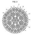
- FIG. 2 is a cross section of a main rope from Figure 1.
- an inner layer rope 21 has: a core rope 22; and a plurality of inner layer strands 23 disposed on outer peripheral portions of the core rope 22.
- the core rope 22 has a plurality of core strands 24.
- Each of the core strands 24 is constructed by twisting a plurality of steel wires 25 together with each other.
- the core strands 24 are twisted together with each other, and the inner layer strands 23 are twisted in a reverse direction to the core strands 24.
- the inner layer strands 23 are constructed by twisting a plurality of steel wires 26 together with each other.
- the cross-sectional structure of the inner layer strands 23 is Warrington-type (Japanese Industrial Standards (JIS) G 3525). Furthermore, there are gaps between adjacent core strands 24 and between the core strands 24 and the inner layer strands 23, but these gaps are eliminated or reduced by tensile forces acting on the main ropes 6 during use.
- An inner layer coating body 27 made of a resin is coated on an outer periphery of the inner layer rope 21.
- the inner layer coating body 27 is composed of a polyethylene resin, for example.
- An outer layer 28 is disposed on an outer peripheral portion of the inner layer coating body 27.
- the outer layer 28 has a plurality of outer layer strands 29.
- Each of the outer layer strands 29 is constituted by: a central wire 30 disposed in the center; and six outer peripheral wires 31 disposed on an outer periphery of the central wire 30.
- the outer layer strands 29 are twisted in a reverse direction to the inner layer strands 23.
- An outer layer coating body 60 is coated on an outer periphery of the outer layer 28.
- the outer layer coating body 60 is constituted by a high-friction resin material having a coefficient of friction greater than or equal to 0.2, such as a polyurethane resin, for example.
- the diameters of all of the wires 25, 26, 30, and 31 are set to less than or equal to 1/400 the diameter of the sheave they are used on, that is, the sheave the main ropes 6 are wound around.
- the weight of the car 8 is twice the capacity (3,200 kg)
- acceleration-deceleration ⁇ /g is 0.08
- the unit weight, of the main ropes 6 is 0.494 kg/m
- the number of main ropes 6 is eight.
- the unit weight of the above main ropes 6 is equivalent to a ⁇ 12 rope (8 x S (19)) employed in a conventional elevator apparatus.
- the weight of the compensating ropes 10 is assumed to be approximately equal to the main ropes 6, and the presence of the tension pulley apparatus 12 has been ignored.
- the traction ratio is: ⁇ (3,200 + 1,600 + 8 ⁇ 0.494 ⁇ TR) ⁇ (1 + 0.08) ⁇ / ⁇ (8 ⁇ 0.494 ⁇ TR) ⁇ (1 - 0.08) ⁇ where TR is the raising and lowering zone (the lifting range).
- the counterweight can be omitted and the planar dimensions of the hoistway 1 can be reduced even if the lifting range is comparatively short.
- the present invention can be applied where TR is greater than or equal to 12.5 m.
- the applicable raising and lowering zone can be changed by altering the coefficient of friction and the contact angle of the main ropes 6 and changing the deadweight and capacity of the car 8, the strength and the number of the main ropes 6, and the weight of the weight 12b to suit the elevator apparatus.
- main ropes 6 having a cross-sectional construction such as that shown in Figure 2, the packing density of the steel wires 25, 26, 30, and 31 can be increased while suppressing the overall diameter, enabling increases in strength. Furthermore, since the contact pressure between the rope grooves of the drive sheave 4a and the main ropes 6 can be reduced, sufficient service life of the main ropes 6 can be maintained while keeping a ratio of the diameter D of the drive sheave 4a to the diameter d of the main ropes 6 (D/d) at equal to or less than 30.
- Embodiment 1 because the compensating ropes 10 are connected between the lower portion of the car 8 and the second end portions 6b of the main ropes 6, the length of the expensive main ropes 6 can be shortened, enabling costs to be reduced.
- rope grooves are shaped as U grooves, damage to the main ropes 6 can be prevented and sufficient friction can be ensured compared to rope grooves having undercuts.
- the compensating ropes 10 are connected between the lower portion of the car 8 and the second end portions 6b of the main ropes 6, but the entire length may also be constituted solely by main ropes composed of the resin-coated rope, the first end portions of the main ropes being connected to the upper portion of the car, and the second end portions of the main ropes being connected to the lower portion of the car. In that case, the number of parts is reduced, enabling installation to be facilitated.
- a resin-coated rope including steel wires is used, but a synthetic fiber rope having a rope main body including synthetic fibers such as aramid fibers, etc., and an outer layer coating body composed of a high-friction resin material, for example, may also be used.
- FIG. 3 is a side elevation showing an elevator apparatus according to Embodiment 2 of the present invention.
- a plurality of main ropes 32 (only one is shown in the Figure 3) are wound around a drive sheave 4a and a deflection sheave 5.
- the main ropes 32 have a cross-sectional construction similar to that in Figure 2.
- Each of the main ropes 32 has a first end portion 32a and a second end portion 32b.
- the first end portions 32a are connected to a machine base 3 in an upper portion of a hoistway 1 by means of rope shackles 33.
- the second end portions 32b are connected to a fixed beam 35 in a bottom portion of the hoistway 1 by means of rope shackles 34.
- An upper traveling block 36 around which the main ropes 32 are wound is disposed on an upper portion of a car 8.
- a lower traveling block 37 around which the main ropes 32 are wound is disposed on a lower portion of the car 8.
- the rest of the construction is similar to that of Embodiment 1.
- the counterweight can also be omitted and the planar dimensions of the hoistway 1 can also be reduced even if the lifting range is comparatively short. Furthermore, since the main ropes 32 are wound around the upper traveling block 36 and the lower traveling block 37 disposed on the car 8, the torque acting on the driving machine 4 can be reduced to approximately half that of Embodiment 1.
- FIG. 4 is a side elevation showing an elevator apparatus according to Embodiment 3 of the present invention
- Figure 5 is a plan showing part of the elevator apparatus in Figure 4.
- a machine room 42 is disposed in an upper portion of a hoistway 41.
- a machine base 43 is secured inside the machine room 42.
- a driving machine (a hoisting machine) 44 and a rotatable deflection sheave 45 are mounted on the machine base 43.
- the driving machine 44 has a drive sheave 44a.
- a plurality of main ropes 46 are wound around the drive sheave 44a and the deflection sheave 45.
- Each of the main ropes 46 has a first end portion 46a and a second end portion 46b.
- the main ropes 46 have a cross-sectional construction similar to that in Figure 2.
- An upper car 47 and a lower car 48 are disposed inside the hoistway 41.
- the upper car 47 is suspended at one end of the main ropes 46 relative to the drive sheave 44a.
- the first end portions 46a of the main ropes 46 are connected to an upper portion of the upper car 47 by means of rope shackles 50.
- the second end portions 46b of the main ropes 46 are connected to the machine base 43 in the upper portion of the hoistway 41 by means of rope shackles 51.
- the lower car 48 is disposed below the upper car 47 so as to overlap with the upper car 47 in a vertical plane of projection.
- a car suspension sheave apparatus 49 is disposed on a lower portion of the lower car 48.
- the car suspension sheave apparatus 49 has a pair of car suspension sheaves (traveling blocks) 49a and 49b. Portions of the main ropes 46 between the drive sheave 44a and the second end portions 46b are wound around the car suspension sheaves 49a and 49b. In other words, the lower car 48 is suspended at the other end of the main ropes 46 relative to the drive sheave 44a.
- a pair of car guide rails 52 for guiding the raising and lowering of the cars 47 and 48 are installed inside the hoistway 41.
- a plurality of rope grooves (not shown) into which the main ropes 46 are inserted are disposed on the drive sheave 44a.
- cross sections of the main ropes 46 are circular, the rope grooves being U grooves (round grooves) having no undercut.
- the main ropes 46 are wound around the drive sheave 44a and the deflection sheave 45 using a full winding method.
- the contact angle of the main ropes 46 on the drive sheave 44a is 320 to 350 degrees (320 - 350 °).
- the upper car 47 and the lower car 48 are suspended by a 2:1 roping method, and since the lower car 48 runs over only half the operating range of the upper car 47, applications are limited to a certain extent.
- the lower car 48 functions in a similar manner to a conventional counterweight, the counterweight can be omitted regardless of the lifting range, enabling the planar dimensions of the hoistway 41 to be reduced.
- the upper car 47 and the lower car 48 have the same weight and the same capacity, there may be a large imbalance in cases where the upper car 47 has a full load (i.e., is full to capacity) and the lower car 48 has no load (i.e., is empty), making it difficult to ensure traction capacity.
- sufficient traction capacity can also be ensured even if there is a large imbalance by using the resin-coated ropes in which the outer layer coating body 60 composed of a high-friction resin material is disposed on the outer peripheral portion as the main ropes 46.
- load fluctuations in the lower car 48 can also be accounted for to ensure sufficient traction capacity while using the lower car 48 instead of a counterweight by using resin-coated ropes as the main ropes 46.
- the diameter of the drive sheave 44a can also be reduced and increases in load torque and braking torque suppressed.
- FIG 6 is a side elevation showing an elevator apparatus according to Embodiment 4 of the present invention
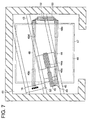
- Figure 7 is a plan showing part of the elevator apparatus in Figure 6.
- a car suspension sheave apparatus 49 is mounted to a lower portion of a lower car 48.
- the car suspension sheave apparatus has: a pair of rotatable first car suspension sheaves 49a and 49b; and a pair of rotatable second car suspension sheaves 49c and 49d.
- the car suspension sheaves 49a, 49b, 49c, and 49d are rotatable about rotating shafts (not shown) extending in a depth direction of the lower car 48. Furthermore, the first car suspension sheaves 49a and 49b and the second car suspension sheaves 49c and 49d are symmetrically disposed in a vertical plane of projection on mutually opposite sides of a straight line connecting a pair of car guide rails 52.
- a rotatable return sheave 53 is disposed in an upper portion inside a hoistway 41.
- the return sheave 53 may be supported by a car guide rails 52, for example.
- Main ropes 46 are wound in sequence from first end portions 46a around a drive sheave 44a, a deflection sheave 45, the drive sheave 44a, the deflection sheave 45, the first car suspension sheaves 49a and 49b, the return sheave 53, and the second car suspension sheaves 49d and 49c to second end portions 46b.
- the rest of the construction is similar to that of Embodiment 3.
- the upper car 47 and the lower car 48 are suspended by a 4:1 roping method, and since the lower car 48 functions in a similar manner to a conventional counterweight, the counterweight can be omitted regardless of the lifting range, enabling the planar dimensions of the hoistway 41 to be reduced.
- the coefficient of friction ⁇ of the outer layer coating body 60 in Embodiments 3 and 4 is preferable to make the coefficient of friction ⁇ of the outer layer coating body 60 in Embodiments 3 and 4 greater than or equal to 0.3.
- the main ropes 46 are fully wound onto the drive sheave 44a, but the present invention is not limited to this configuration, and either full winding or half winding can be appropriately selected depending on the weight and capacity of the upper car 47 and the lower car 48, and the coefficient of friction of the main ropes 46, etc.
- the ranges of movement of the upper car 47 and the lower car 48 are different.
- the range of movement of the lower car 48 might be from the first floor to the twentieth floor
- the range of movement of the upper car 47 might be from the twenty-first floor to the uppermost floor.
- the present invention can be applied to a building having facilities such as restaurants, etc., on the twentieth floor, and having an observation platform on the uppermost floor, for example.
- the range of movement of the lower car 48 is smaller than the range of movement of the upper car 47, but the range of movement of the lower car 48 may be made greater instead.
- the lower car need merely be suspended from the first end portions of the main ropes, the car suspension sheave apparatus mounted to an upper portion or a lower portion of the upper car, and the second end portions connected to an upper portion of the hoistway.
- the car suspension sheave apparatus mounted to an upper portion or a lower portion of the upper car
- the second end portions connected to an upper portion of the hoistway.
Landscapes
- Engineering & Computer Science (AREA)
- Structural Engineering (AREA)
- Civil Engineering (AREA)
- Mechanical Engineering (AREA)
- Automation & Control Theory (AREA)
- Lift-Guide Devices, And Elevator Ropes And Cables (AREA)
Abstract
Description
Claims (8)
- An elevator apparatus comprising:wherein traction capacity is ensured without using a counterweight by using as said main rope a resin-coated rope in which an outer layer coating body composed of a high-friction resin material is disposed on an outer peripheral portion.a hoistway;a driving machine having a drive sheave;a main rope wound around said drive sheave;anda car suspended by said main rope and raised and lowered inside said hoistway by said driving machine,
- The elevator apparatus according to Claim 1, wherein:a coefficient of friction of said outer layer coating body is greater than or equal to 0.6.
- The elevator apparatus according to Claim 1, wherein:an upper portion buffer is disposed in an upper portion inside said hoistway, for alleviating mechanical shock if said car collides with a ceiling portion of said hoistway.
- The elevator apparatus according to Claim 1, wherein:said main rope has a first end portion and a second end portion;said car is suspended by said first end portion of said main rope; anda compensating rope is connected between a lower portion of said car and said second end portion of said main rope, for compensating for weight balance fluctuations in said main rope dependent on a position of said car.
- The elevator apparatus according to Claim 1, wherein:said main rope has a first end portion connected to an upper portion of said hoistway and a second end portion connected to a bottom portion of said hoistway;an upper traveling block around which said main rope is wound is disposed on an upper portion of said car, and a lower traveling block around which said main rope is wound is disposed on a lower portion of said car; anda tension pulley apparatus having a tension pulley around which said main rope is wound is disposed in a bottom portion inside said hoistway, for applying a tensile force to said main rope.
- An elevator apparatus comprising:wherein a resin-coated rope in which an outer layer coating body composed of a high-friction resin material is disposed on an outer peripheral portion is used as said main rope,a hoistway;a driving machine having a drive sheave;a main rope wound around said drive sheave;andan upper car suspended by one end of said main rope relative to said drive sheave and raised and lowered inside said hoistway by said driving machine,
and
a lower car raised and lowered inside said hoistway by said driving machine is suspended at the other end of said main rope relative to said drive sheave and is disposed below said upper car so as to overlap with said upper car in a vertical plane of projection. - The elevator apparatus according to Claim 6, wherein:said main rope has a first end portion connected to an upper portion of said upper car and a second end portion connected to an upper portion inside said hoistway;a car suspension sheave apparatus is disposed on a lower portion of said lower car; anda portion of said main rope between said drive sheave and said second end portion is wound around said car suspension sheave apparatus.
- The elevator apparatus according to Claim 7, wherein:said car suspension sheave apparatus has a plurality of rotatable first car suspension sheaves and a plurality of rotatable second car suspension sheaves;a rotatable return sheave is disposed on an upper portion inside said hoistway; andsaid main rope is wound in sequence from said first end portion around said drive sheave, said first car suspension sheaves, said return sheave, and said second car suspension sheaves to said second end portion.
Applications Claiming Priority (1)
| Application Number | Priority Date | Filing Date | Title |
|---|---|---|---|
| PCT/JP2002/005304 WO2003101876A1 (en) | 2002-05-30 | 2002-05-30 | Elevator device |
Publications (2)
| Publication Number | Publication Date |
|---|---|
| EP1508544A1 true EP1508544A1 (en) | 2005-02-23 |
| EP1508544A4 EP1508544A4 (en) | 2008-04-23 |
Family
ID=29606633
Family Applications (1)
| Application Number | Title | Priority Date | Filing Date |
|---|---|---|---|
| EP02733257A Withdrawn EP1508544A4 (en) | 2002-05-30 | 2002-05-30 | LIFTING APPARATUS |
Country Status (5)
| Country | Link |
|---|---|
| EP (1) | EP1508544A4 (en) |
| JP (1) | JPWO2003101876A1 (en) |
| KR (1) | KR100636870B1 (en) |
| CN (1) | CN1264740C (en) |
| WO (1) | WO2003101876A1 (en) |
Cited By (1)
| Publication number | Priority date | Publication date | Assignee | Title |
|---|---|---|---|---|
| EP1951439A4 (en) * | 2005-10-27 | 2010-05-12 | Otis Elevator Co | ELEVATOR LOAD SUSPENSION ASSEMBLY COMPRISING A SHEATH WITH SEVERAL POLYMER COMPOSITIONS |
Families Citing this family (2)
| Publication number | Priority date | Publication date | Assignee | Title |
|---|---|---|---|---|
| SG141343A1 (en) * | 2006-09-29 | 2008-04-28 | Inventio Ag | Synthetic fibre cable and lift installation with such a synthetic fibre cable |
| CN102491151A (en) * | 2011-12-16 | 2012-06-13 | 苏州市东沪电缆有限公司 | Pseudo trailing elevator cable assembly |
Family Cites Families (17)
| Publication number | Priority date | Publication date | Assignee | Title |
|---|---|---|---|---|
| JPS57121683A (en) * | 1980-12-27 | 1982-07-29 | Shinko Wire Co Ltd | Wire rope |
| JPS5863666A (en) * | 1981-10-06 | 1983-04-15 | 三菱電機株式会社 | Well bucket type elevator |
| JPS6019679A (en) * | 1983-07-14 | 1985-01-31 | 株式会社東芝 | Elevator device |
| JPS61169475A (en) * | 1985-01-22 | 1986-07-31 | 三菱電機株式会社 | Elevator |
| JPH0419021Y2 (en) * | 1987-10-30 | 1992-04-28 | ||
| JPH0755780B2 (en) | 1989-12-05 | 1995-06-14 | 三菱電機株式会社 | Traction type elevator equipment |
| JPH0755780A (en) | 1993-08-06 | 1995-03-03 | Yanako Bunseki Kogyo Kk | High sensitivity measuring apparatus for ultra-trace ingredient in various gas by gas chromatograph |
| JP3252575B2 (en) * | 1993-12-17 | 2002-02-04 | 三菱電機株式会社 | Elevator equipment |
| CZ282660B6 (en) * | 1994-03-02 | 1997-08-13 | Inventio Ag | Bearer rope of lifting and transport facilities |
| JPH0921084A (en) * | 1995-07-06 | 1997-01-21 | Yamamori Giken Kogyo Kk | Wire rope structure |
| JP2002504473A (en) * | 1998-02-26 | 2002-02-12 | オーチス エレベータ カンパニー | Double sheave rope type elevator system using flat flexible rope |
| JP3225224B2 (en) * | 1998-04-10 | 2001-11-05 | 東京製綱繊維ロープ株式会社 | High strength fiber rope |
| JP3724322B2 (en) * | 2000-03-15 | 2005-12-07 | 株式会社日立製作所 | Wire rope and elevator using it |
| KR100511850B1 (en) | 2000-08-09 | 2005-09-02 | 미쓰비시덴키 가부시키가이샤 | Elevator device |
| EP1199276B1 (en) * | 2000-10-20 | 2003-01-22 | Dätwyler Ag Schweizerische Kabel-, Gummi- Und Kunststoffwerke | Compensation weight and elevator system |
| JP2002145556A (en) | 2000-11-13 | 2002-05-22 | Mitsubishi Electric Corp | Elevator equipment |
| JP7055780B2 (en) * | 2019-08-28 | 2022-04-18 | 株式会社三共 | Pachinko machine |
-
2002
- 2002-05-30 EP EP02733257A patent/EP1508544A4/en not_active Withdrawn
- 2002-05-30 CN CNB028114868A patent/CN1264740C/en not_active Expired - Fee Related
- 2002-05-30 WO PCT/JP2002/005304 patent/WO2003101876A1/en not_active Ceased
- 2002-05-30 JP JP2004509578A patent/JPWO2003101876A1/en active Pending
- 2002-05-30 KR KR1020047000592A patent/KR100636870B1/en not_active Expired - Fee Related
Cited By (2)
| Publication number | Priority date | Publication date | Assignee | Title |
|---|---|---|---|---|
| EP1951439A4 (en) * | 2005-10-27 | 2010-05-12 | Otis Elevator Co | ELEVATOR LOAD SUSPENSION ASSEMBLY COMPRISING A SHEATH WITH SEVERAL POLYMER COMPOSITIONS |
| US9546447B2 (en) | 2005-10-27 | 2017-01-17 | Otis Elevator Company | Elevator load bearing assembly having a jacket with multiple polymer compositions |
Also Published As
| Publication number | Publication date |
|---|---|
| CN1514799A (en) | 2004-07-21 |
| KR20040019067A (en) | 2004-03-04 |
| WO2003101876A1 (en) | 2003-12-11 |
| EP1508544A4 (en) | 2008-04-23 |
| KR100636870B1 (en) | 2006-10-19 |
| CN1264740C (en) | 2006-07-19 |
| JPWO2003101876A1 (en) | 2005-09-29 |
Similar Documents
| Publication | Publication Date | Title |
|---|---|---|
| US20060196731A1 (en) | Elevator apparatus | |
| JP4391640B2 (en) | More synthetic fiber rope | |
| EP1329412B1 (en) | Elevator device | |
| JP4748832B2 (en) | Synthetic fiber rope driven by rope sheave | |
| JP4327959B2 (en) | Synthetic fiber rope | |
| JP2001262482A (en) | Wire rope and elevator using it | |
| EP1586526A1 (en) | Elevator rope | |
| JP2004521050A (en) | elevator | |
| EP2634130A1 (en) | Rope for elevator | |
| EP1820765A1 (en) | Rope for elevator and elevator | |
| EP2042462B1 (en) | Elevator apparatus | |
| CN100439227C (en) | Elevator rope and elevator device | |
| JP5859138B2 (en) | Elevator system belt | |
| JP4879391B2 (en) | Rope turning system and appropriate synthetic fiber rope and rope drive system | |
| EP1721859B1 (en) | Elevator compensating cable having a selected loop radius and associated method | |
| EP1508544A1 (en) | Elevator device | |
| EP1312573B1 (en) | Elevator device | |
| KR100830777B1 (en) | Elevator ropes and elevator devices | |
| EP2281768A1 (en) | Elevator device | |
| KR100691667B1 (en) | Elevator device | |
| KR100563114B1 (en) | Elevator ropes and elevator devices | |
| KR100744737B1 (en) | Elevator ropes and elevator devices | |
| HK1081506A1 (en) | Elevator comprising a belt-like transmission means, particularly comprising a v-ribbed belt, as supporting and/or traction means |
Legal Events
| Date | Code | Title | Description |
|---|---|---|---|
| PUAI | Public reference made under article 153(3) epc to a published international application that has entered the european phase |
Free format text: ORIGINAL CODE: 0009012 |
|
| 17P | Request for examination filed |
Effective date: 20031127 |
|
| AK | Designated contracting states |
Kind code of ref document: A1 Designated state(s): AT BE CH CY DE DK ES FI FR GB GR IE IT LI LU MC NL PT SE TR |
|
| AX | Request for extension of the european patent |
Extension state: AL LT LV MK RO SI |
|
| DAX | Request for extension of the european patent (deleted) | ||
| RBV | Designated contracting states (corrected) |
Designated state(s): DE |
|
| RAP1 | Party data changed (applicant data changed or rights of an application transferred) |
Owner name: MITSUBISHI DENKI KABUSHIKI KAISHA |
|
| A4 | Supplementary search report drawn up and despatched |
Effective date: 20080326 |
|
| RIC1 | Information provided on ipc code assigned before grant |
Ipc: B66B 11/00 20060101ALI20080318BHEP Ipc: B66B 9/00 20060101ALI20080318BHEP Ipc: B66B 7/06 20060101AFI20031218BHEP |
|
| 17Q | First examination report despatched |
Effective date: 20120608 |
|
| STAA | Information on the status of an ep patent application or granted ep patent |
Free format text: STATUS: THE APPLICATION IS DEEMED TO BE WITHDRAWN |
|
| 18D | Application deemed to be withdrawn |
Effective date: 20141202 |