EP1508483A1 - Kfz-Sicherheitseinrichtung, insbesondere Kfz-Sicherheitsnetz - Google Patents
Kfz-Sicherheitseinrichtung, insbesondere Kfz-Sicherheitsnetz Download PDFInfo
- Publication number
- EP1508483A1 EP1508483A1 EP03018551A EP03018551A EP1508483A1 EP 1508483 A1 EP1508483 A1 EP 1508483A1 EP 03018551 A EP03018551 A EP 03018551A EP 03018551 A EP03018551 A EP 03018551A EP 1508483 A1 EP1508483 A1 EP 1508483A1
- Authority
- EP
- European Patent Office
- Prior art keywords
- pawl
- cam
- vehicle safety
- safety device
- motor vehicle
- Prior art date
- Legal status (The legal status is an assumption and is not a legal conclusion. Google has not performed a legal analysis and makes no representation as to the accuracy of the status listed.)
- Granted
Links
- 239000000463 material Substances 0.000 claims abstract description 44
- 238000004804 winding Methods 0.000 claims description 33
- 230000033001 locomotion Effects 0.000 claims description 30
- 238000000605 extraction Methods 0.000 claims description 10
- 230000000903 blocking effect Effects 0.000 claims description 6
- 238000010276 construction Methods 0.000 description 7
- 230000001133 acceleration Effects 0.000 description 2
- 238000009434 installation Methods 0.000 description 2
- 230000003993 interaction Effects 0.000 description 2
- 230000003111 delayed effect Effects 0.000 description 1
- 230000002349 favourable effect Effects 0.000 description 1
- 239000004519 grease Substances 0.000 description 1
- 238000003780 insertion Methods 0.000 description 1
- 230000037431 insertion Effects 0.000 description 1
- 230000009545 invasion Effects 0.000 description 1
- 238000004519 manufacturing process Methods 0.000 description 1
- 238000000034 method Methods 0.000 description 1
- 230000002093 peripheral effect Effects 0.000 description 1
- 239000000837 restrainer Substances 0.000 description 1
- 210000002023 somite Anatomy 0.000 description 1
Images


Classifications
-
- B—PERFORMING OPERATIONS; TRANSPORTING
- B60—VEHICLES IN GENERAL
- B60R—VEHICLES, VEHICLE FITTINGS, OR VEHICLE PARTS, NOT OTHERWISE PROVIDED FOR
- B60R21/00—Arrangements or fittings on vehicles for protecting or preventing injuries to occupants or pedestrians in case of accidents or other traffic risks
- B60R21/02—Occupant safety arrangements or fittings, e.g. crash pads
- B60R21/06—Safety nets, transparent sheets, curtains, or the like, e.g. between occupants and glass
Definitions
- the invention relates to a motor vehicle safety device, in particular a motor vehicle safety net, according to the preamble of Claim 1.
- Automotive safety devices which include load compartment covers and in the broadest sense also sun blinds are known and widely used.
- the vehicle safety devices are used to separate the vehicle passenger compartment from the vehicle compartment to prevent in the event of strong accelerations, such as a strong deceleration of the vehicle or in the event of a crash, cargo from the hold into the passenger compartment be thrown into it.
- motor vehicle safety nets are arranged in a roller blind housing, which is arranged on the side facing the cargo space side of the backrest of the rear passenger seat.
- the safety net can be transferred from a wound rest position into a tensioned use position corresponding to a predetermined extension length of the material web, for which purpose, for example, an end element arranged on a free end region of the material web, such as a holding rod, can be fixed on the motor vehicle side.
- an end element arranged on a free end region of the material web such as a holding rod
- the backrest of the rear vehicle seat in Direction can be pivoted forward, for example, to to provide a larger cargo area.
- substantially horizontally arranged backrest is the automotive safety net aufspannbar and can be a position of use occupy, in which it separates the hold from the passenger compartment.
- the total length of the bearing is on the winding shaft Material web adapted to this longer distance.
- the object of the invention is an easy to provide a built vehicle safety device with a low number of items and doing a high Security offers.
- the invention solves this problem with the features of Claim 1, in particular with those of the characterizing part, and is Accordingly, characterized in that the pawl a Movement Delay is assigned to the incident movement of the Pawl from its freewheeling position into its locked position slowed down.
- the principle of the invention is thus essentially now directly the pawl aeazasverzögerer attributable to the incidence movement of the pawl in her Lock position slowed down.
- the control curve can be simpler Way be designed so that they except for a recess is formed circular and over the entire pull-out of the Material web until reaching the predetermined extension length Invasion of the pawl prevented in its locked position, wherein upon reaching the predetermined extension length, the one Ein rehabilitation the material web corresponds, a position of the control cam, For example, a circumferential rotational position is achieved in the this recess is arranged so that a collapse of the Pawl in its locked position is possible.
- the motion retarder ensures that the Pawl when pulling the web of material not in their Lock position falls into it, but also the excess length Material web can be deducted.
- the control curve goes through while, for example, a rotation angle of more than 360 °.
- One with the Pawl, for example, firmly connected control pin can so fast relative to the recess of the control cam at this Recess be moved past that an incident movement of the Pawl into its locked position does not take place.
- the Pawl is assigned, which can be in the prior art relatively complex arrangement with several spring elements omitted.
- DE 198 49 927 which There is shown in Figures 8 to 13, is next to a Cam element still provided a cam. Either Cam element as well as cam plate can the incident movement prevent the pawl into its locked position.
- One Time delay element acts here on the rotational movement of the cam relative to the winding shaft.
- this second Mechanism that requires a variety of items, practical completely eliminated.
- the invention is only a single Cam element necessary because the motion retarder of the Pawl is assigned.
- the respective circumferential rotational position of the drive wheel as well as the driven cam element correlate in this way directly with the circumferential rotational position of the winding shaft or with the respective extension length of the material web.
- An intermediate circuit of spring elements is unnecessary in this respect.
- the motor vehicle safety device according to the invention is a Construction possible, which requires significantly fewer parts.
- the Vehicle safety device can be constructed with little effort and mountable.
- the motor vehicle safety device according to the invention offers a high security, because the pawl automatically, when the predetermined pull-out length is reached, time-delayed - enters the blocking position.
- the motor vehicle safety device leaves it over addition to the possibility that a user the material web on the pulls out predetermined Ausziehin out and in particular for the case that the winding shaft fixed relative to a pivoting vehicle seat back the rear vehicle seat is arranged. In the case, that this backrest in the direction of travel forward, ie in an im essentially horizontal position is pivoted and Accordingly, a greater distance between the winding shaft and the vehicle side provided hook-in recordings according to a second extension length, which is greater than the predetermined Extraction length, consists, the material web can without obstruction until pulled out to this second extension length. Since the Movement retarder prevents an immediate collapse of the pawl, is another deduction of the web over the predetermined extraction length not locked when the Extraction process is continuous.
- the entire stock Material web, which is mounted on the winding shaft, in its length the second extension length corresponds.
- the material web in a position of use according to the second extension length is removed, so far no additional supply of Material web on the winding shaft, so that in this case no separate locking mechanism is needed.
- the Pawl pivotally trained is the Pawl pivotally trained.
- This configuration allows a particularly simple construction and an advantageous Interaction with locking teeth of the locking disc.
- a control lever together with the pawl is pivotable about the axis of the pawl.
- control lever is a deceleration surface, in particular a Delay toothing assigned.
- a delay surface is first a geometric surface of any shape called, with the motion restrainer cooperates, and insofar the Delaying the incidence movement of the pawl of the Movement retarder transmits to the pawl. It can work for example, act around a friction surface.
- Embodiment of the invention is the delay surface as a delay toothing educated.
- the design offers in particular the possibility that Delay surface at one of the pivot axis of the Control lever remote end of the control lever to arrange, so that favorable balance of power can be achieved. Overall, on this A particularly simple construction can be achieved.
- the cam element is rotatably mounted.
- This configuration allows in a particularly simple manner, a control curve, which extends over a Rotation angle of the cam member of about 360 degrees.
- this embodiment allows a particularly simple Training such that a pull-out of the web to to the predetermined extension length of about one turn of the Cam element corresponds to nearly 360 degrees and a Extraction movement of the material web up to a second Extracting length of rotation of the cam element by more than 360 Degree corresponds.
- the cam element has a cam which extends over a Rotation angle range of about 360 degrees.
- This embodiment offers the possibility of a particularly simple Training the cam element with cam and allows a particularly simple construction of the motor vehicle safety device according to the invention.
- a further advantageous embodiment of the invention corresponds to a pull-out movement of the material web up to the predetermined extension length substantially the rotation of the Control curve by almost 360 degrees.
- a further advantageous embodiment of the invention corresponds to the extraction movement of the material web up to a second extension length, which is greater than the predetermined extension length a rotation of the control cam by more than 360 degrees.
- automotive safety device is used, for example, especially in case that it is a motor vehicle-type separator Safety net acts on a backrest 14 of a motor vehicle 15th attached.
- winding shaft 12 FIG. 2
- the Housing 11 can, as shown in Fig. 1, on the back of the R Backrest 14 approximately in the region of the upper free end of the Backrest 14 may be arranged.
- the safety net 13 When the seat back 14 is in an upright position (shown in phantom), the safety net 13 can be pulled out in accordance with a predetermined pull-out length l 1 , thus bridging the distance between the roller blind housing 11 and the motor vehicle skies 17.
- Receiving 18 provided in which, for example, the ends of a net-holding rod set, in particular can be mounted. These recordings 18 show FIG. 1 only schematically.
- the distance between the Einhtician-receptacles 18 and the blind housing 11 is greater than the predetermined extension length L 1 .
- the motor vehicle safety net 13 must be pulled out in accordance with a second extension length I 2 .
- Fig. 1 shows the two different positions of the backrest 14 with appropriately extended motor vehicle safety net 13, wherein for the two different positions of the backrest 14th different Einhnature recordings 18 are provided.
- the cam member 30 provides a control cam 32, which at axial viewing (in the direction of the axis 31) of the toothing 29th is immediately adjacent.
- the cam 32 includes a Section 33 with a substantially constant radius, which is about 270 degrees.
- a Recess 34 belongs to the cam 32 a Recess 34, which represents a section with a smaller radius (Fig. 3).
- the control lever 36 cooperates with the pawl 22 and is together with this about the pivot axis 38 pivotally.
- the Pawl 22 is formed substantially U-shaped and is located approximately equally on both sides of the Mounting plate 25 so that it passes through.
- left U-leg 39 cooperates with the pawl 22 with the Control lever 36 and with respect to FIG. 2, right U-leg 40th cooperates the pawl 22 with the locking disc 20th
- control lever 36 At the bottom with respect to FIG. 2 of the control lever 36, ie essentially at a maximum distance from its pivot axis 38 the control lever 36 has a delay toothing 41.
- These Delay toothing 41 cooperates with the toothing 42 of atecsverzögerers 43, which directly on the mounting plate 25 is attached.
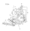
- Fig. 3 shows a position of the pawl 22 in freewheeling position, in the pawl 22 is spaced from the locking disc 20.
- the operation of the device is approximately as follows:
- the Cam element 30 is in a zero position, in the Figures is not shown.
- the zero position of the cam member 30th approximately corresponds to one about 90 degrees with respect to FIG. 3 against the Clockwise about the pivot axis 31 twisted cam member 30th
- the Recess 34 is immediately adjacent.
- the section 44 of the Control cam 32 ensures that in this zero position, the pawl 22 is held in freewheeling position, a removal of the material web thirteenth in the unwinding b of the winding shaft 12 is therefore possible.
- the user can now choose one at the free end of the Material web 13 arranged end element, such as a net-holding rod, take off and unplug the net 13.
- the winding shaft 12th and accordingly also the drive wheel 27 thus lead a Rotary movement in the direction of rotation of the arrow b about the axis 31 around by.
- By engagement of the tooth 28 of the drive wheel 27 with the Gearing 29 of the cam member 30 is at a full Rotation of the drive wheel 27 in the counterclockwise direction Cam member 30 in the clockwise direction by a step angle 45 turned.
- the teeth 28, 29 of the drive wheel and cam member are coordinated so that after a certain number of revolutions of the winding shaft 12 corresponding to a predetermined extension length l 1 of the network 13, the cam member 30 of a rotation of nearly 360 degrees (in the embodiment about 315 degrees ) has gone through.
- the cam member 30 has been rotated by about 315 degrees clockwise from the zero position, not shown, so that a position in FIG. 3 has been passed and finally a circumferential rotational position of the cam member 30, as shown in Fig. 4, is achieved.
- the cam follower 35 reaches, since the control lever 36 is loaded by the spring element 37 in incident-Rraum, the bottom of the recess 34 so that the pawl 22 in its locking position shown in FIG. 4 can fall into it.
- the incidence movement as described above, slowed down due to theincisverzögerers 43.
- the user intervenes e.g. the support rod and can the material web 13 while exercising the Retraction force of the spring motor, not shown, of the winding shaft 12th wrap.
- the flat slopes of the ratchet teeth 21 of the locking disc 22 can slide along the pawl 22, wherein through the Winding the cam member 30 against the Turned back to its zero position clockwise.
- the drive wheel 27 and the cam member 30 act insofar as a counting mechanism, which is the current extraction length of the Material web 13 by counting the revolutions of the winding shaft 12th finds.
- the motor vehicle safety device 10 allows a Construction with only a very small number of components, so that a simple assembly is possible. Besides, this way can achieved a particularly flat and thus space-saving design become. Finally, can be dispensed with elaborate springs, the an inexpensive production of a motor vehicle safety device according to the invention 10 allow.
Landscapes
- Engineering & Computer Science (AREA)
- Mechanical Engineering (AREA)
- Seats For Vehicles (AREA)
- Braking Arrangements (AREA)
- Air-Conditioning For Vehicles (AREA)
Abstract
Description
Das Sicherheitsnetz ist von einer aufgewickelten Ruhelage in eine aufgespannte Gebrauchslage entsprechend einer vorbestimmten Ausziehlänge der Werkstoffbahn überführbar, wozu beispielsweise ein an einem freien Endbereich der Werkstoffbahn angeordnetes Endelement, wie eine Haltestange, kraftfahrzeugseitig festgelegt werden kann. In aufgespanntem Zustand versperrt das Kfz-Sicherheitsnetz die zwischen dem oberen Rand der Rückenlehne und dem Kfz-Himmel ansonsten verbleibende Öffnung.
- Fig. 1
- schematisch in teilgeschnittener Seitenansicht den Innenraum eines Kfz's im Bereich des hinteren Fahrzeugsitzes, mit in zwei unterschiedlichen Gebrauchslagen dargestellter Sitz-Rückenlehne,
- Fig. 2
- schematisch in perspektivischer Explosionsansicht die Bauteile eines Ausführungsbeispiels der erfindungsgemäßen Kfz-Sicherheitseinrichtung,
- Fig. 3
- in schematischer, teilgeschnittener Seitenansicht etwa gemäß Ansichtspfeil III in Fig. 2 die zusammengebaute Anordnung der Fig. 2 mit in Freilaufstellung befindlicher Sperrklinke, und
- Fig. 4
- eine Darstellung gemäß Fig. 3 mit in Sperrstellung befindlicher Sperrklinke.
Während der Ausziehbewegung der Werkstoffbahn 13 in einem Zug bis zur zweiten Ausziehlänge l2 gerät zwar der Nockenfolger 35 kurzfristig in den Bereich der Ausnehmung 34 der Nockenscheibe 30. Auf Grund des Bewegungsverzögerers 43 kommt es jedoch nicht zu einem Einfallen der Sperrklinke 22 in ihre Sperrposition.
Claims (10)
- Kfz-Sicherheitseinrichtung (10), insbesondere Kfz-Sicherheitsnetz, mit einer eine flexible, abziehbare Werkstoffbahn (13) tragenden Wickelwelle (12), die drehfest mit einer Rastscheibe (20) verbunden ist, die mit einer zwischen einer Freilaufstellung (Fig. 3) und einer Sperrstellung (Fig. 4) verlagerbaren Sperrklinke (22) kooperiert, und mit einem Zählmechanismus, der ein drehfest mit der Wickelwelle (12) verbundenes Antriebsrad (27) und ein eine Steuerkurve (32) aufweisendes, angetriebenes Nockenelement (30) umfasst, wobei die Steuerkurve (32) bei vollständig aufgewickelter Werkstoffbahn (12) die Sperrklinke (22) in ihrer Freilaufstellung hält, und wobei die Steuerkurve (32) ein Einfallen der Sperrklinke (22) in ihre Sperrposition hinein zulässt, wenn die Werkstoffbahn (13) bis zu einer vorbestimmten Ausziehlänge (I1) ausgezogen ist, dadurch gekennzeichnet, dass der Sperrklinke (22) ein Bewegungsverzögerer (43) zugeordnet ist, der die Einfallbewegung der Sperrklinke (22) von ihrer Freilaufstellung in ihre Sperrstellung hinein verlangsamt.
- Kfz-Sicherheitseinrichtung nach Anspruch 1, dadurch gekennzeichnet, daß die Sperrklinke (22) schwenkbar ausgebildet ist.
- Kfz-Sicherheitseinrichtung nach Anspruch 2, dadurch gekennzeichnet, daß mit der Sperrklinke (22) ein Steuerhebel (36) zusammenwirkt, der gemeinsam mit der Sperrklinke (22) um die Achse (38) der Sperrklinke schwenkbar ist.
- Kfz-Sicherheitseinrichtung nach Anspruch 3, dadurch gekennzeichnet, daß dem Steuerhebel (36) eine Verzögerungsfläche, insbesondere eine Verzögerungsverzahnung (41) zugeordnet ist.
- Kfz-Sicherheitseinrichtung nach einem der vorangegangenen Ansprüche, dadurch gekennzeichnet, daß sich die Steuerkurve (32) über einen Drehwinkelbereich von etwa 360° erstreckt.
- Kfz-Sicherheitseinrichtung nach einem der vorangegangenen Ansprüche, dadurch gekennzeichnet, daß das Nockenelement (30) drehgelagert ist.
- Kfz-Sicherheitseinrichtung nach Anspruch 6, dadurch gekennzeichnet, daß eine Ausziehbewegung der Werkstoffbahn (13) bis zu der vorbestimmten Ausziehlänge (l1) im wesentlichen einer Drehung der Steuerkurve (32) und/oder des Nockenelementes (30) um nahezu 360° entspricht.
- Kfz-Sicherheitseinrichtung nach einem der vorangegangenen Ansprüche, dadurch gekennzeichnet, daß die Werkstoffbahn (13) bis zu einer zweiten Ausziehlänge (l2) ausziehbar ist, die größer ist als die vorbestimmte Ausziehlänge (l1).
- Kfz-Sicherheitseinrichtung nach Anspruch 8, dadurch gekennzeichnet, daß die Ausziehbewegung der Werkstoffbahn (13) bis zu der zweiten Ausziehlänge (l2) einer Drehung der Steuerkurve (32) und/oder des Nockenelementes (30) um mehr als 360° entspricht.
- Kfz-Sicherheitseinrichtung nach einem der vorangegangenen Ansprüche, dadurch gekennzeichnet, daß die Steuerkurve (32) bezüglich einer Drehachse (31) des Nockenelementes (30) einen Abschnitt (33) mit im wesentlichen konstanten Radius besitzt und eine Ausnehmung (34) mit geringerem Radius aufweist.
Priority Applications (3)
| Application Number | Priority Date | Filing Date | Title |
|---|---|---|---|
| EP03018551A EP1508483B1 (de) | 2003-08-18 | 2003-08-18 | Kfz-Sicherheitseinrichtung, insbesondere Kfz-Sicherheitsnetz |
| DE50311052T DE50311052D1 (de) | 2003-08-18 | 2003-08-18 | Kfz-Sicherheitseinrichtung, insbesondere Kfz-Sicherheitsnetz |
| AT03018551T ATE419995T1 (de) | 2003-08-18 | 2003-08-18 | Kfz-sicherheitseinrichtung, insbesondere kfz- sicherheitsnetz |
Applications Claiming Priority (1)
| Application Number | Priority Date | Filing Date | Title |
|---|---|---|---|
| EP03018551A EP1508483B1 (de) | 2003-08-18 | 2003-08-18 | Kfz-Sicherheitseinrichtung, insbesondere Kfz-Sicherheitsnetz |
Publications (2)
| Publication Number | Publication Date |
|---|---|
| EP1508483A1 true EP1508483A1 (de) | 2005-02-23 |
| EP1508483B1 EP1508483B1 (de) | 2009-01-07 |
Family
ID=34042853
Family Applications (1)
| Application Number | Title | Priority Date | Filing Date |
|---|---|---|---|
| EP03018551A Expired - Lifetime EP1508483B1 (de) | 2003-08-18 | 2003-08-18 | Kfz-Sicherheitseinrichtung, insbesondere Kfz-Sicherheitsnetz |
Country Status (3)
| Country | Link |
|---|---|
| EP (1) | EP1508483B1 (de) |
| AT (1) | ATE419995T1 (de) |
| DE (1) | DE50311052D1 (de) |
Citations (4)
| Publication number | Priority date | Publication date | Assignee | Title |
|---|---|---|---|---|
| DE19708192C1 (de) * | 1997-02-28 | 1998-04-23 | Butz Peter Verwaltung | Laderaum-Trennvorrichtung für Kraftwagen, insbesondere für Kombinations-Personenkraftwagen |
| DE19849927A1 (de) * | 1997-11-10 | 1999-06-02 | Butz Peter Verwaltung | Sicherheitseinrichtung für Fahrzeuge, insbesondere Laderaum-Trennvorrichtung für Kraftwagen, wie zum Beispiel für Kombinations-Personenkraftwagen o. dgl. |
| DE10127463A1 (de) * | 2001-06-07 | 2002-12-19 | Butz Peter Verwaltung | Sicherheitseinrichtung für Fahrzeuge |
| DE10207575A1 (de) * | 2002-02-22 | 2003-09-11 | Butz Peter Verwaltung | Kfz-Sicherheitseinrichtung, insbesondere Kfz-Sicherheitsnetz |
-
2003
- 2003-08-18 DE DE50311052T patent/DE50311052D1/de not_active Expired - Lifetime
- 2003-08-18 AT AT03018551T patent/ATE419995T1/de not_active IP Right Cessation
- 2003-08-18 EP EP03018551A patent/EP1508483B1/de not_active Expired - Lifetime
Patent Citations (4)
| Publication number | Priority date | Publication date | Assignee | Title |
|---|---|---|---|---|
| DE19708192C1 (de) * | 1997-02-28 | 1998-04-23 | Butz Peter Verwaltung | Laderaum-Trennvorrichtung für Kraftwagen, insbesondere für Kombinations-Personenkraftwagen |
| DE19849927A1 (de) * | 1997-11-10 | 1999-06-02 | Butz Peter Verwaltung | Sicherheitseinrichtung für Fahrzeuge, insbesondere Laderaum-Trennvorrichtung für Kraftwagen, wie zum Beispiel für Kombinations-Personenkraftwagen o. dgl. |
| DE10127463A1 (de) * | 2001-06-07 | 2002-12-19 | Butz Peter Verwaltung | Sicherheitseinrichtung für Fahrzeuge |
| DE10207575A1 (de) * | 2002-02-22 | 2003-09-11 | Butz Peter Verwaltung | Kfz-Sicherheitseinrichtung, insbesondere Kfz-Sicherheitsnetz |
Also Published As
| Publication number | Publication date |
|---|---|
| EP1508483B1 (de) | 2009-01-07 |
| ATE419995T1 (de) | 2009-01-15 |
| DE50311052D1 (de) | 2009-02-26 |
Similar Documents
| Publication | Publication Date | Title |
|---|---|---|
| EP0941177B1 (de) | Sicherheitsnetzanordnung mit vereinfachter bedienung | |
| DE2947472C2 (de) | ||
| EP1060956B1 (de) | Trenneinrichtung mit variabler Rückzugskraft | |
| EP1205361B1 (de) | Trennvorrichtung für ein Kraftfahrzeug | |
| DE3331281A1 (de) | Sitzgurt-rueckholvorrichtung mit automatisch gespeicherter zugspannungsfreier stellung | |
| EP0504482B1 (de) | Antrieb für einen translatorisch ausfahrbaren Überrollbügel | |
| DE19820641B4 (de) | Gurtaufwickeleinrichtung | |
| DE2646559A1 (de) | Einziehvorrichtung fuer sitzgurte mit verringerbarer zugkraft | |
| DE19750715C1 (de) | Rollovorrichtung für ein Fahrzeugdach mit transparenter Dachscheibe | |
| DE60302948T2 (de) | Gurtaufroller | |
| DE3227094C2 (de) | Passives Fahrzeuginsassen-Rückhaltegurtsystem | |
| EP0914989B1 (de) | Sicherheitseinrichtung für Kraftfahrzeuge, insbesondere Laderaumtrennvorrichtung für Kombinations-Personenkraftwagen od. dgl | |
| WO1982004021A1 (en) | Winding device for the strap of a safety belt,particularly for motor vehicles | |
| EP1359067A2 (de) | Gurtaufroller für einen Fahrzeug-Sicherheitsgurt | |
| DE10349178B4 (de) | Gurtstrafferaggregat | |
| EP3478521B1 (de) | Beschattungsvorrichtung für eine scheibe eines kraftfahrzeugs | |
| EP0152909B1 (de) | Vorrichtung zum selbsttätigen Aufrollen eines Fahrzeugsicherheitsgurtes | |
| DE102015003675B3 (de) | Laderaumabdeckung mit einer Trennnetzfunktion für ein Fahrzeug | |
| DE10207575B4 (de) | Kfz-Sicherheitseinrichtung, insbesondere Kfz-Sicherheitsnetz | |
| DE3933453A1 (de) | Gurtaufroller | |
| EP1775165A1 (de) | Abdeckvorrichtung für einen Laderaum eines Kraftfahrzeugs | |
| DE4226818C2 (de) | Energierückgewinnungsvorrichtung für radgetriebene Fahrzeuge | |
| DE3523290C2 (de) | ||
| EP1508483B1 (de) | Kfz-Sicherheitseinrichtung, insbesondere Kfz-Sicherheitsnetz | |
| DE2745591C2 (de) | In Notsituationen sperrende Einziehvorrichtung für Sicherheitsgurte mit verringerbarer Gurtzugkraft |
Legal Events
| Date | Code | Title | Description |
|---|---|---|---|
| PUAI | Public reference made under article 153(3) epc to a published international application that has entered the european phase |
Free format text: ORIGINAL CODE: 0009012 |
|
| AK | Designated contracting states |
Kind code of ref document: A1 Designated state(s): AT BE BG CH CY CZ DE DK EE ES FI FR GB GR HU IE IT LI LU MC NL PT RO SE SI SK TR |
|
| AX | Request for extension of the european patent |
Extension state: AL LT LV MK |
|
| 17P | Request for examination filed |
Effective date: 20050226 |
|
| AKX | Designation fees paid |
Designated state(s): AT BE BG CH CY CZ DE DK EE ES FI FR GB GR HU IE IT LI LU MC NL PT RO SE SI SK TR |
|
| GRAP | Despatch of communication of intention to grant a patent |
Free format text: ORIGINAL CODE: EPIDOSNIGR1 |
|
| GRAS | Grant fee paid |
Free format text: ORIGINAL CODE: EPIDOSNIGR3 |
|
| GRAA | (expected) grant |
Free format text: ORIGINAL CODE: 0009210 |
|
| AK | Designated contracting states |
Kind code of ref document: B1 Designated state(s): AT BE BG CH CY CZ DE DK EE ES FI FR GB GR HU IE IT LI LU MC NL PT RO SE SI SK TR |
|
| REG | Reference to a national code |
Ref country code: GB Ref legal event code: FG4D Free format text: NOT ENGLISH |
|
| REG | Reference to a national code |
Ref country code: CH Ref legal event code: EP |
|
| REG | Reference to a national code |
Ref country code: IE Ref legal event code: FG4D Free format text: LANGUAGE OF EP DOCUMENT: GERMAN |
|
| REF | Corresponds to: |
Ref document number: 50311052 Country of ref document: DE Date of ref document: 20090226 Kind code of ref document: P |
|
| PG25 | Lapsed in a contracting state [announced via postgrant information from national office to epo] |
Ref country code: NL Free format text: LAPSE BECAUSE OF FAILURE TO SUBMIT A TRANSLATION OF THE DESCRIPTION OR TO PAY THE FEE WITHIN THE PRESCRIBED TIME-LIMIT Effective date: 20090107 Ref country code: SI Free format text: LAPSE BECAUSE OF FAILURE TO SUBMIT A TRANSLATION OF THE DESCRIPTION OR TO PAY THE FEE WITHIN THE PRESCRIBED TIME-LIMIT Effective date: 20090107 |
|
| NLV1 | Nl: lapsed or annulled due to failure to fulfill the requirements of art. 29p and 29m of the patents act | ||
| PG25 | Lapsed in a contracting state [announced via postgrant information from national office to epo] |
Ref country code: FI Free format text: LAPSE BECAUSE OF FAILURE TO SUBMIT A TRANSLATION OF THE DESCRIPTION OR TO PAY THE FEE WITHIN THE PRESCRIBED TIME-LIMIT Effective date: 20090107 Ref country code: ES Free format text: LAPSE BECAUSE OF FAILURE TO SUBMIT A TRANSLATION OF THE DESCRIPTION OR TO PAY THE FEE WITHIN THE PRESCRIBED TIME-LIMIT Effective date: 20090418 |
|
| REG | Reference to a national code |
Ref country code: IE Ref legal event code: FD4D |
|
| PG25 | Lapsed in a contracting state [announced via postgrant information from national office to epo] |
Ref country code: PT Free format text: LAPSE BECAUSE OF FAILURE TO SUBMIT A TRANSLATION OF THE DESCRIPTION OR TO PAY THE FEE WITHIN THE PRESCRIBED TIME-LIMIT Effective date: 20090608 Ref country code: SE Free format text: LAPSE BECAUSE OF FAILURE TO SUBMIT A TRANSLATION OF THE DESCRIPTION OR TO PAY THE FEE WITHIN THE PRESCRIBED TIME-LIMIT Effective date: 20090407 |
|
| PG25 | Lapsed in a contracting state [announced via postgrant information from national office to epo] |
Ref country code: DK Free format text: LAPSE BECAUSE OF FAILURE TO SUBMIT A TRANSLATION OF THE DESCRIPTION OR TO PAY THE FEE WITHIN THE PRESCRIBED TIME-LIMIT Effective date: 20090107 Ref country code: CZ Free format text: LAPSE BECAUSE OF FAILURE TO SUBMIT A TRANSLATION OF THE DESCRIPTION OR TO PAY THE FEE WITHIN THE PRESCRIBED TIME-LIMIT Effective date: 20090107 Ref country code: IE Free format text: LAPSE BECAUSE OF FAILURE TO SUBMIT A TRANSLATION OF THE DESCRIPTION OR TO PAY THE FEE WITHIN THE PRESCRIBED TIME-LIMIT Effective date: 20090107 Ref country code: EE Free format text: LAPSE BECAUSE OF FAILURE TO SUBMIT A TRANSLATION OF THE DESCRIPTION OR TO PAY THE FEE WITHIN THE PRESCRIBED TIME-LIMIT Effective date: 20090107 |
|
| PLBE | No opposition filed within time limit |
Free format text: ORIGINAL CODE: 0009261 |
|
| STAA | Information on the status of an ep patent application or granted ep patent |
Free format text: STATUS: NO OPPOSITION FILED WITHIN TIME LIMIT |
|
| PG25 | Lapsed in a contracting state [announced via postgrant information from national office to epo] |
Ref country code: RO Free format text: LAPSE BECAUSE OF FAILURE TO SUBMIT A TRANSLATION OF THE DESCRIPTION OR TO PAY THE FEE WITHIN THE PRESCRIBED TIME-LIMIT Effective date: 20090107 Ref country code: SK Free format text: LAPSE BECAUSE OF FAILURE TO SUBMIT A TRANSLATION OF THE DESCRIPTION OR TO PAY THE FEE WITHIN THE PRESCRIBED TIME-LIMIT Effective date: 20090107 |
|
| 26N | No opposition filed |
Effective date: 20091008 |
|
| PG25 | Lapsed in a contracting state [announced via postgrant information from national office to epo] |
Ref country code: BG Free format text: LAPSE BECAUSE OF FAILURE TO SUBMIT A TRANSLATION OF THE DESCRIPTION OR TO PAY THE FEE WITHIN THE PRESCRIBED TIME-LIMIT Effective date: 20090407 |
|
| BERE | Be: lapsed |
Owner name: BOS G.M.B.H. & CO. KG Effective date: 20090831 |
|
| PG25 | Lapsed in a contracting state [announced via postgrant information from national office to epo] |
Ref country code: MC Free format text: LAPSE BECAUSE OF NON-PAYMENT OF DUE FEES Effective date: 20090831 |
|
| REG | Reference to a national code |
Ref country code: CH Ref legal event code: PL |
|
| GBPC | Gb: european patent ceased through non-payment of renewal fee |
Effective date: 20090818 |
|
| PG25 | Lapsed in a contracting state [announced via postgrant information from national office to epo] |
Ref country code: LI Free format text: LAPSE BECAUSE OF NON-PAYMENT OF DUE FEES Effective date: 20090831 Ref country code: CH Free format text: LAPSE BECAUSE OF NON-PAYMENT OF DUE FEES Effective date: 20090831 |
|
| REG | Reference to a national code |
Ref country code: FR Ref legal event code: ST Effective date: 20100430 |
|
| PG25 | Lapsed in a contracting state [announced via postgrant information from national office to epo] |
Ref country code: BE Free format text: LAPSE BECAUSE OF NON-PAYMENT OF DUE FEES Effective date: 20090831 |
|
| PG25 | Lapsed in a contracting state [announced via postgrant information from national office to epo] |
Ref country code: FR Free format text: LAPSE BECAUSE OF NON-PAYMENT OF DUE FEES Effective date: 20090831 |
|
| PG25 | Lapsed in a contracting state [announced via postgrant information from national office to epo] |
Ref country code: GR Free format text: LAPSE BECAUSE OF FAILURE TO SUBMIT A TRANSLATION OF THE DESCRIPTION OR TO PAY THE FEE WITHIN THE PRESCRIBED TIME-LIMIT Effective date: 20090408 |
|
| PG25 | Lapsed in a contracting state [announced via postgrant information from national office to epo] |
Ref country code: GB Free format text: LAPSE BECAUSE OF NON-PAYMENT OF DUE FEES Effective date: 20090818 Ref country code: AT Free format text: LAPSE BECAUSE OF NON-PAYMENT OF DUE FEES Effective date: 20090818 |
|
| PG25 | Lapsed in a contracting state [announced via postgrant information from national office to epo] |
Ref country code: IT Free format text: LAPSE BECAUSE OF FAILURE TO SUBMIT A TRANSLATION OF THE DESCRIPTION OR TO PAY THE FEE WITHIN THE PRESCRIBED TIME-LIMIT Effective date: 20090107 |
|
| PG25 | Lapsed in a contracting state [announced via postgrant information from national office to epo] |
Ref country code: LU Free format text: LAPSE BECAUSE OF NON-PAYMENT OF DUE FEES Effective date: 20090818 |
|
| PG25 | Lapsed in a contracting state [announced via postgrant information from national office to epo] |
Ref country code: HU Free format text: LAPSE BECAUSE OF FAILURE TO SUBMIT A TRANSLATION OF THE DESCRIPTION OR TO PAY THE FEE WITHIN THE PRESCRIBED TIME-LIMIT Effective date: 20090708 |
|
| PG25 | Lapsed in a contracting state [announced via postgrant information from national office to epo] |
Ref country code: TR Free format text: LAPSE BECAUSE OF FAILURE TO SUBMIT A TRANSLATION OF THE DESCRIPTION OR TO PAY THE FEE WITHIN THE PRESCRIBED TIME-LIMIT Effective date: 20090107 |
|
| PG25 | Lapsed in a contracting state [announced via postgrant information from national office to epo] |
Ref country code: CY Free format text: LAPSE BECAUSE OF FAILURE TO SUBMIT A TRANSLATION OF THE DESCRIPTION OR TO PAY THE FEE WITHIN THE PRESCRIBED TIME-LIMIT Effective date: 20090107 |
|
| PGFP | Annual fee paid to national office [announced via postgrant information from national office to epo] |
Ref country code: DE Payment date: 20210819 Year of fee payment: 19 |
|
| REG | Reference to a national code |
Ref country code: DE Ref legal event code: R119 Ref document number: 50311052 Country of ref document: DE |
|
| PG25 | Lapsed in a contracting state [announced via postgrant information from national office to epo] |
Ref country code: DE Free format text: LAPSE BECAUSE OF NON-PAYMENT OF DUE FEES Effective date: 20230301 |