EP1508313A1 - Doppelhülliges Stenteinbringungssystem - Google Patents
Doppelhülliges Stenteinbringungssystem Download PDFInfo
- Publication number
- EP1508313A1 EP1508313A1 EP04019410A EP04019410A EP1508313A1 EP 1508313 A1 EP1508313 A1 EP 1508313A1 EP 04019410 A EP04019410 A EP 04019410A EP 04019410 A EP04019410 A EP 04019410A EP 1508313 A1 EP1508313 A1 EP 1508313A1
- Authority
- EP
- European Patent Office
- Prior art keywords
- stent
- sheath
- graft
- deployment system
- secondary sheath
- Prior art date
- Legal status (The legal status is an assumption and is not a legal conclusion. Google has not performed a legal analysis and makes no representation as to the accuracy of the status listed.)
- Granted
Links
Images


Classifications
-
- A—HUMAN NECESSITIES
- A61—MEDICAL OR VETERINARY SCIENCE; HYGIENE
- A61F—FILTERS IMPLANTABLE INTO BLOOD VESSELS; PROSTHESES; DEVICES PROVIDING PATENCY TO, OR PREVENTING COLLAPSING OF, TUBULAR STRUCTURES OF THE BODY, e.g. STENTS; ORTHOPAEDIC, NURSING OR CONTRACEPTIVE DEVICES; FOMENTATION; TREATMENT OR PROTECTION OF EYES OR EARS; BANDAGES, DRESSINGS OR ABSORBENT PADS; FIRST-AID KITS
- A61F2/00—Filters implantable into blood vessels; Prostheses, i.e. artificial substitutes or replacements for parts of the body; Appliances for connecting them with the body; Devices providing patency to, or preventing collapsing of, tubular structures of the body, e.g. stents
- A61F2/95—Instruments specially adapted for placement or removal of stents or stent-grafts
- A61F2/9517—Instruments specially adapted for placement or removal of stents or stent-grafts handle assemblies therefor
-
- Y—GENERAL TAGGING OF NEW TECHNOLOGICAL DEVELOPMENTS; GENERAL TAGGING OF CROSS-SECTIONAL TECHNOLOGIES SPANNING OVER SEVERAL SECTIONS OF THE IPC; TECHNICAL SUBJECTS COVERED BY FORMER USPC CROSS-REFERENCE ART COLLECTIONS [XRACs] AND DIGESTS
- Y10—TECHNICAL SUBJECTS COVERED BY FORMER USPC
- Y10S—TECHNICAL SUBJECTS COVERED BY FORMER USPC CROSS-REFERENCE ART COLLECTIONS [XRACs] AND DIGESTS
- Y10S623/00—Prosthesis, i.e. artificial body members, parts thereof, or aids and accessories therefor
- Y10S623/902—Method of implanting
- Y10S623/903—Blood vessel
Definitions
- This invention relates generally to medical devices and procedures, and more particularly to a method and system of deploying a stent-graft in a vascular system.
- Prostheses for implantation in blood vessels or other similar organs of the living body are, in general, well known in the medical art.
- prosthetic vascular grafts formed of biocompatible materials (e.g., Dacron or expanded, porous polytetrafluoroethylene (PTFE) tubing) have been employed to replace or bypass damaged or occluded natural blood vessels.
- a graft material supported by framework is known as a stent-graft or endoluminal graft.
- stent-grafts for treatment or isolation of vascular aneurysms and vessel walls which have been thinned or thickened by disease (endoluminal repair or exclusion) are well known.
- stent-grafts are "self-expanding", i.e., inserted into the vascular system in a compressed or contracted state, and permitted to expand upon removal of a restraint.
- Self-expanding stent-grafts typically employ a wire or tube configured (e.g. bent or cut) to provide an outward radial force and employ a suitable elastic material such as stainless steel or Nitinol (nickel-titanium). Nitinol may additionally employ shape memory properties.
- the self-expanding stent-graft is typically configured in a tubular shape of a slightly greater diameter than the diameter of the blood vessel in which the stent-graft is intended to be used.
- stent-grafts are preferably deployed through a less invasive intraluminal delivery, i.e., cutting through the skin to access a lumen or vasculature or percutaneously via successive dilatation, at a convenient (and less traumatic) entry point, and routing the stent-graft through the lumen to the site where the prosthesis is to be deployed.
- Intraluminal deployment is typically effected using a delivery catheter with coaxial inner (plunger) and outer (sheath) tubes arranged for relative axial movement.
- the stent graft is compressed and disposed within the distal end of an outer catheter tube in front of an inner tube.
- the catheter is then maneuvered, typically routed though a lumen (e.g., vessel), until the end of the catheter (and the stent-graft) is positioned in the vicinity of the intended treatment site.
- the inner tube is then held stationary while the outer tube of the delivery catheter is withdrawn.
- the inner tube prevents the stent-graft from being withdrawn with the outer tube.
- the stent-graft radially expands so that at least a portion of it is in substantially conforming surface contact with a portion of the interior of the lumen e.g., blood vessel wall.
- stent-graft deployment systems use only a semi-rigid sheath in the deployment systems.
- the semi-rigid sheath provides columnar strength to advance the system through access vessels in the body.
- the semi-rigid sheath may tend to kink in areas having tight radiuses such as the thoracic arch. Such kinking can increase the deployment force required to place a stent-graft in a target area or even prevent deployment completely. Even if kinking can be avoided, use of a semi-rigid sheath may still increase the pushing force needed to overcome frictional resistance required to deploy the stent-graft to the target area.
- a stent-graft deployment system comprises a retractable primary sheath, a secondary sheath initially covered by the retractable primary sheath, a stent-graft initially retained within the secondary sheath, and a deployment means for deploying the stent-graft.
- the secondary sheath is more flexible than the retractable primary sheath.
- the retractable primary sheath can contain the stent-graft in a first constrained small diameter configuration and the secondary sheath can be disposed within the retractable primary sheath and also contain the stent-graft.
- the flexible secondary sheath contains the stent-graft in a second constrained small diameter configuration. The removal of the secondary sheath releases the stent-graft from a radial constraint so that stent-graft deployment may proceed.
- a stent-graft deployment system before deployment includes a stent-graft constricted within the flexible secondary sheath, a semi-rigid sheath around the flexible secondary sheath, the semi-rigid sheath being retracted to expose the flexible secondary sheath, and the flexible secondary sheath being retractable such that the stent-graft expands as the flexible secondary sheath is retracted.
- a device for implanting a radially self-expanding endoprosthesis comprises an outer sheath which is more rigid and axially maneuverable than an inner sheath.
- the outer sheath is disposed over the inner sheath. While in a second position the outer sheath is retracted to expose the inner sheath.
- the device further comprises an axially maneuverable elongated catheter coupled to the inner sheath. In a first position the inner sheath retains the radially self-expanding endoprosthesis. As the inner sheath is moved to a second position by for example pulling the proximal end of the inner sheath, the radially self-expanding endoprosthesis is deployed.
- a stent-graft deployment system includes a stent-graft and a catheter having a catheter shaft having a tip; a retractable primary sheath and a retractable flexible secondary sheath.
- the flexible secondary sheath contains the stent-graft in a second constrained small diameter configuration around the catheter shaft at a stent graft location of the catheter near the tip and within the retractable primary sheath.
- the flexible secondary sheath containing the stent graft in the second constrained small diameter configuration is exposed and an end portion of the catheter from an end of the tip to a retracted end of the primary sheath has substantially reduced resistance to bending as compared to when the primary sheath is covering the stent graft location of the catheter. Removal of the secondary sheath releases the stent-graft from a radial constraint so that stent-graft deployment occurs as the secondary sheath releases.
- Removal of the retractable secondary sheath occurs through a secondary sheath retraction handle connected to a proximal end of the retractable flexible secondary sheath, such that retraction of the secondary sheath retraction handle causes a proximal end of the retractable flexible secondary sheath to be pulled along a catheter longitudinal axis toward a proximal end of the catheter. Pulling of the proximal end of the retractable flexible secondary sheath tensions the retractable flexible sheath to retract the sheath along the catheter longitudinal axis to cause progressive deployment of the stent graft from a distal end of the stent graft.
- a method of deploying a stent-graft includes the steps of loading the stent-graft deployment system with a stent-graft, tracking the stent-graft deployment system over a guide wire to a location before a target area which may include a curved portion, and retracting a primary sheath to expose a secondary sheath within said primary sheath while the primary sheath is retracted or held as the secondary sheath is exposed, the stent-graft is moved to its location within the target area or moved until its location within the target area is confirmed.
- the method further includes the steps of further tracking the stent-graft deployment system to place the secondary sheath in the curved portion of the target area, and retracting the secondary sheath to at least partially deploy the stent-graft in the target area and may include releasing the stent-graft from the delivery system using a release mechanism
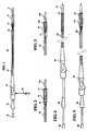
- FIG. 1 is a plan view of a stent-graft deployment system without a stent-graft in accordance with the present invention (not to scale);
- FIG. 2 is a close up schematic plan view of the end of the deployment system of FIG. 1 having a loaded stent-graft;
- FIG. 3 is a close up schematic plan view of the end of the deployment system of FIG. 1 showing an alternative retention mechanism with a loaded stent-graft;
- FIG. 4 illustrates the stent-graft deployment system of FIG. 1 with a primary sheath covering a secondary sheath (in dashed lines);
- FIG. 5 illustrates the stent-graft deployment system of FIG. 1 with the primary sheath retracted and the secondary sheath exposed;
- FIG. 6 illustrates the stent-graft deployment system of FIG. 1 with the primary sheath retracted and the secondary sheath partially retracted;
- FIG. 7 illustrates the stent-graft deployment system of FIG. 1 with the primary sheath retracted with the secondary sheath almost completely retracted;
- FIG. 8 illustrates the stent-graft deployment system of FIG. 1 with the secondary sheath completely retracted and the stent-graft fully deployed;
- FIG. 9 is a flow chart illustrating the steps of a method in accordance with the present invention.
- FIG. 10 is a schematic diagram illustrating the stent-graft deployment system initially inserted to a location adjacent (before) a tight curved target area;
- FIG. 11 is a schematic diagram illustrating the stent-graft deployment system showing the primary sheath retracted and the secondary sheath exposed;
- FIG. 12 is a schematic diagram illustrating the stent-graft deployment system with the secondary sheath which is exposed advanced into the tight curve;
- FIG. 13 is a schematic diagram illustrating the stent-graft deployment system with the secondary sheath which has been advanced into the curve is partially retracted and the stent-graft is partially deployed;
- FIG. 14 is a schematic diagram illustrating the stent-graft deployment system with the secondary sheath being completely retracted and a stent-graft being fully deployed;
- FIG. 15 is a schematic diagram illustrating the stent-graft fully deployed with the stem-graft deployment system removed in accordance with the present invention.
- FIGS. 1-3 show portions of a stent-graft deployment system 10.
- FIG. 1 illustrates the system 10 without a stent-graft while FIGS. 2 and 3 show close up views of the deployment system tip which are loaded with a stent-graft 15, 15a.
- This system could also deploy a stent alone or some other form of endoprosthesis.
- the subsequent use of "stent-graft" herein should be understood to include other forms of endoprosthesis.
- the stent-graft deployment system 10 comprises a tapered tip 12, 12a, 12b that is flexible and able to provide trackability in tight and tortuous vessels, and can bend easily once the primary sheath 20 is retracted. Other tip shapes such as bullet-shaped tips could also be used.
- the system 10 includes a primary sheath 20 (preferably made of a semi-rigid material such as PTFE) initially covering a secondary sheath 14 (preferably made of woven polyethylene terephthalate (PET)).
- the secondary sheath 14 is more flexible than the retractable primary sheath 20.
- the deployment system 10 is able to separately retract the primary and secondary sheaths.
- the primary sheath should have enough stiffness to provide adequate trackability and column strength as the system 10 tracks through tortuous vessels to avoid buckling or kinking.
- the secondary sheath utilizes its greater flexibility (at the expense of column strength) to improve trackability and pushability, particularly through areas having tight radiuses. So, where prior deployment systems utilizing just a semi-rigid primary sheath were prone to kinking while tracking through an area with a tight radius. Use of the secondary sheath avoids kinking or changes in shape and reduces resistance to deployment (reduced advancement force) while tracking through vessels with tight curves.
- the deployment system 10 also includes a stent-graft 15 initially retained within the secondary sheath 14.
- the stent-graft 15 is preferably a self-expanding, Nitinol/Dacron stent-graft system designed for endovascular exclusion of Thoracic Aortic Aneurisms (TAA).
- TAA Thoracic Aortic Aneurisms
- the deployment system 10 includes a cup 16 as shown in FIG. 2 or alternatively steel runners 17 as shown in FIG. 3 that eventually release the stem-graft by its mere self-expansion to act as a means for retaining the stent-graft 15 in place during deployment.
- a handle or a hub 22 is fixed to the primary sheath 20
- a second handle or hub (24) near a proximal end of the stent-graft deployment system 10 is fixed to the secondary sheath, and a catheter shaft including a shaft handle 26 is connected to and aids the advancement of the system 10 and acts as a deployment means.
- the deployment system 10 shown includes a flush port 28 and a radiopaque marker 18 allowing for accurate positioning of the delivery system prior to deployment of the stent-graft in the proximal position.
- FIGS. 4-8 and FIGS. 10-15 the stent-graft deployment system 10 is shown in various stages as it is advances over a guide wire 111 (as shown in FIGS. 10-14) and the stent-graft is deployed.
- FIGS. 4-8 illustrate the stent-graft deployment system 10 as it would operate or function outside or apart from the body.
- FIGS. 10-15 illustrate the stent-graft deployment system as it would operate when tracking over a guide wire 111 within a body and particularly through a target area (vessel) having a tight curvature or radius (21).
- FIGS. 4 and 10 both illustrate the stent-graft deployment system 10 with the primary sheath 20 covering the secondary sheath 14.
- the flexible secondary sheath 14 is arranged within the semi-rigid sheath 20 when the semi-rigid sheath 20 is in a non-retracted position as shown in FIG. 4.
- the stent-graft 15 is constrained solely by the flexible secondary sheath 14 and further illustrates a handle or hub 22 coupled to the semi-rigid sheath 20 serving as a first arrangement for retracting the semi-rigid sheath 20 and exposing the flexible secondary sheath 14 as well as an inner tube 25 coupled to the flexible secondary sheath 14 serving as a second arrangement for retracting the flexible secondary sheath and enabling the stent-graft to expand.
- the exposed portion of the flexible secondary sheath 14 could have a diameter larger than the semi-rigid primary sheath 20 that surrounded the flexible secondary sheath 14 previously.
- the larger diameter of the exposed portion of the flexible secondary sheath 14 is a contributory factor in reducing the force needed to retract the secondary sheath.
- the first arrangement described above could comprise (as previously mentioned) the handle or hub 22 coupled to the semi-rigid sheath 20 enabling the relative axial movement of the semi-rigid sheath 20 over a remainder of the stent-graft deployment system and the second arrangement could comprise an inner tube 25 coupled to the flexible secondary sheath 14 that enables relative axial movement of the flexible secondary sheath 14 relative to the semi-rigid sheath 20 and the longitudinal axis of the catheter.
- the system 10 can be advanced over the guide wire 111 with a lower advancement force since the secondary sheath is designed to be quite flexible particularly in areas with tight radiuses (2 1 ) as shown in FIG. 12.
- the tight arch 21 is meant to represent any area or vessels with tight radiuses such as the thoracic arch.
- FIGS. 6 and 13 in each instance the primary sheath has been retracted and the secondary sheath is shown partially retracted with the stent-graft 15 being partially deployed. As the secondary sheath retracts, more and more of the stent-graft is deployed as shown in FIGS. 6-8 and FIGS. 13-15.
- FIGS. 8 and 14 illustrate the stent-graft deployment system 10 with the secondary sheath 14 completely retracted and the stent-graft 15 fully deployed.
- FIG. 15 the stent-graft deployment system 10 has been removed.
- the stent-graft deployment system 10 can also be thought of as a device for implanting a radially self-expanding endoprosthesis 15 having an outer sheath 20.
- the outer sheath 20 is more rigid and axially maneuverable relative to an inner sheath 14 and wherein the outer sheath 20 is disposed over the inner sheath 14 in a first position (as shown in FIG. 5) and exposes the inner sheath 14 in a second position (as shown in FIGS. 6-8).
- the system 10 can also include an elongated catheter 25 coupled to the inner sheath 14, wherein the inner sheath 14 is constructed to retain the radially self-expanding endoprosthesis 15 in a first position and enable deployment of the radially self-expanding endoprosthesis 15 in a second position.
- a flow chart illustrates a method 100 of deploying a stent-graft includes the steps of providing a stent-graft deployment system with a stent-graft 102, tracking the stent-graft deployment system over a guide wire to a location before a target area 104, which may include a curved portion, and retracting the primary sheath to expose a secondary sheath within the target area while the primary sheath is retracted or held as the secondary sheath is exposed 106.
- the stent-graft is moved to its location within the target area or until its location within the target area is confirmed.
- the method further includes the steps of further tracking the stent-graft deployment system to place the secondary sheath in the curved portion of the target area 108, and retracting the secondary sheath to at least partially deploy the stent-graft in the target area 110.
- This step may include deploying or releasing the stent-graft from the delivery system using a release mechanism 112.
- the device may also be considered to have a first predeployment configuration wherein said first and second sheaths surround the stent graft to be deployed, and a second partial deployment configuration where the primary sheath is fully retract so that the primary sheath no longer constrains the stent graft to be deployed, while the secondary sheath still constrains the stent graft to be deployed, and third fully deployed configuration where said stent graft is fully released from the primary and secondary sheaths.
- the relative movement of the tubular is such that the axial centerline of the cylinder forming the sheaths is moved without the sheaths being everted between their respective predeployment configurations and their respective post deployment configurations such that the axial centerline of the cylinder of each sheath moves in substantially one motion (in a linear movement along a curving path) along the axial centerline of the catheter along which it is moved
- the present configuration is well suited for introducing the stent-graft deployment system into a femoral artery and advancing the stent-graft deployment system through an iliac artery into the aorta for repair of an aortic aneurysm and more specifically in tracking the stent-graft deployment system through a portion of an thoracic arch when the secondary sheath has been exposed after the retraction of the primary sheath and without any kinking of the primary sheath.
Landscapes
- Health & Medical Sciences (AREA)
- Engineering & Computer Science (AREA)
- Biomedical Technology (AREA)
- Cardiology (AREA)
- Oral & Maxillofacial Surgery (AREA)
- Transplantation (AREA)
- Heart & Thoracic Surgery (AREA)
- Vascular Medicine (AREA)
- Life Sciences & Earth Sciences (AREA)
- Animal Behavior & Ethology (AREA)
- General Health & Medical Sciences (AREA)
- Public Health (AREA)
- Veterinary Medicine (AREA)
- Prostheses (AREA)
Applications Claiming Priority (2)
| Application Number | Priority Date | Filing Date | Title |
|---|---|---|---|
| US641825 | 1996-05-02 | ||
| US10/641,825 US6945990B2 (en) | 2003-08-16 | 2003-08-16 | Double sheath deployment system |
Publications (2)
| Publication Number | Publication Date |
|---|---|
| EP1508313A1 true EP1508313A1 (de) | 2005-02-23 |
| EP1508313B1 EP1508313B1 (de) | 2008-12-10 |
Family
ID=34063440
Family Applications (1)
| Application Number | Title | Priority Date | Filing Date |
|---|---|---|---|
| EP04019410A Expired - Lifetime EP1508313B1 (de) | 2003-08-16 | 2004-08-16 | Doppelhülliges Stenteinbringungssystem |
Country Status (3)
| Country | Link |
|---|---|
| US (2) | US6945990B2 (de) |
| EP (1) | EP1508313B1 (de) |
| DE (1) | DE602004018237D1 (de) |
Cited By (6)
| Publication number | Priority date | Publication date | Assignee | Title |
|---|---|---|---|---|
| WO2006037084A1 (en) * | 2004-09-28 | 2006-04-06 | Cordis Corporation | Thin film medical device and delivery system |
| WO2010002931A1 (en) * | 2008-07-01 | 2010-01-07 | Endologix, Inc. | Catheter system |
| WO2011160965A1 (en) * | 2010-06-25 | 2011-12-29 | Angiomed Gmbh & Co. Medizintechnik Kg | Delivery system for a self-expanding implant |
| US9687374B2 (en) | 2011-03-01 | 2017-06-27 | Endologix, Inc. | Catheter system and methods of using same |
| US10390929B2 (en) | 2003-09-03 | 2019-08-27 | Bolton Medical, Inc. | Methods of self-aligning stent grafts |
| US11129737B2 (en) | 2015-06-30 | 2021-09-28 | Endologix Llc | Locking assembly for coupling guidewire to delivery system |
Families Citing this family (97)
| Publication number | Priority date | Publication date | Assignee | Title |
|---|---|---|---|---|
| US7727253B2 (en) * | 2000-11-03 | 2010-06-01 | Cook Incorporated | Medical grasping device having embolic protection |
| US7776052B2 (en) * | 2000-11-03 | 2010-08-17 | Cook Incorporated | Medical grasping device |
| US7753918B2 (en) * | 2000-11-03 | 2010-07-13 | William A. Cook Australia Pty. Ltd. | Medical grasping device |
| US7713275B2 (en) * | 2000-11-03 | 2010-05-11 | Cook Incorporated | Medical grasping device |
| US7753917B2 (en) | 2000-11-03 | 2010-07-13 | Cook Incorporated | Medical grasping device |
| US8721713B2 (en) | 2002-04-23 | 2014-05-13 | Medtronic, Inc. | System for implanting a replacement valve |
| WO2004103450A1 (ja) * | 2003-05-23 | 2004-12-02 | Kabushikikaisha Igaki Iryo Sekkei | ステント供給装置 |
| US20080264102A1 (en) | 2004-02-23 | 2008-10-30 | Bolton Medical, Inc. | Sheath Capture Device for Stent Graft Delivery System and Method for Operating Same |
| US8500792B2 (en) | 2003-09-03 | 2013-08-06 | Bolton Medical, Inc. | Dual capture device for stent graft delivery system and method for capturing a stent graft |
| US8292943B2 (en) | 2003-09-03 | 2012-10-23 | Bolton Medical, Inc. | Stent graft with longitudinal support member |
| US11259945B2 (en) | 2003-09-03 | 2022-03-01 | Bolton Medical, Inc. | Dual capture device for stent graft delivery system and method for capturing a stent graft |
| US11596537B2 (en) | 2003-09-03 | 2023-03-07 | Bolton Medical, Inc. | Delivery system and method for self-centering a proximal end of a stent graft |
| US20070198078A1 (en) | 2003-09-03 | 2007-08-23 | Bolton Medical, Inc. | Delivery system and method for self-centering a Proximal end of a stent graft |
| US9198786B2 (en) | 2003-09-03 | 2015-12-01 | Bolton Medical, Inc. | Lumen repair device with capture structure |
| US7393358B2 (en) * | 2004-08-17 | 2008-07-01 | Boston Scientific Scimed, Inc. | Stent delivery system |
| US20060155366A1 (en) * | 2005-01-10 | 2006-07-13 | Laduca Robert | Apparatus and method for deploying an implantable device within the body |
| US8128680B2 (en) | 2005-01-10 | 2012-03-06 | Taheri Laduca Llc | Apparatus and method for deploying an implantable device within the body |
| US8287583B2 (en) * | 2005-01-10 | 2012-10-16 | Taheri Laduca Llc | Apparatus and method for deploying an implantable device within the body |
| DE102005003632A1 (de) | 2005-01-20 | 2006-08-17 | Fraunhofer-Gesellschaft zur Förderung der angewandten Forschung e.V. | Katheter für die transvaskuläre Implantation von Herzklappenprothesen |
| US7632296B2 (en) * | 2005-03-03 | 2009-12-15 | Boston Scientific Scimed, Inc. | Rolling membrane with hydraulic recapture means for self expanding stent |
| EP3613387B1 (de) * | 2005-04-04 | 2023-01-11 | Flexible Stenting Solutions, Inc. | Flexibler stent |
| US8359723B2 (en) | 2005-06-30 | 2013-01-29 | Abbott Vascular Inc. | Introducer sheath and methods of making |
| US20100130937A1 (en) * | 2005-06-30 | 2010-05-27 | Abbott Vascular Inc. | Introducer sheath and methods of making |
| US9168359B2 (en) * | 2005-06-30 | 2015-10-27 | Abbott Laboratories | Modular introducer and exchange sheath |
| US9352118B2 (en) * | 2005-06-30 | 2016-05-31 | Abbott Laboratories | Modular introducer and exchange sheath |
| US20080004571A1 (en) * | 2006-06-28 | 2008-01-03 | Abbott Laboratories | Expandable introducer sheath |
| US8801744B2 (en) * | 2006-06-28 | 2014-08-12 | Abbott Laboratories | Expandable introducer sheath to preserve guidewire access |
| US8440122B2 (en) * | 2005-06-30 | 2013-05-14 | Abbott Vascular Inc. | Introducer sheath and methods of making |
| US9597063B2 (en) * | 2006-06-28 | 2017-03-21 | Abbott Laboratories | Expandable introducer sheath to preserve guidewire access |
| US8038704B2 (en) * | 2005-07-27 | 2011-10-18 | Paul S. Sherburne | Stent and other objects removal from a body |
| US20070043420A1 (en) * | 2005-08-17 | 2007-02-22 | Medtronic Vascular, Inc. | Apparatus and method for stent-graft release using a cap |
| US9375215B2 (en) * | 2006-01-20 | 2016-06-28 | W. L. Gore & Associates, Inc. | Device for rapid repair of body conduits |
| US8535368B2 (en) | 2006-05-19 | 2013-09-17 | Boston Scientific Scimed, Inc. | Apparatus for loading and delivering a stent |
| US9889275B2 (en) | 2006-06-28 | 2018-02-13 | Abbott Laboratories | Expandable introducer sheath to preserve guidewire access |
| US20100198160A1 (en) * | 2006-06-28 | 2010-08-05 | Abbott Vascular Inc. | Expandable Introducer Sheaths and Methods for Manufacture and Use |
| US8348995B2 (en) | 2006-09-19 | 2013-01-08 | Medtronic Ventor Technologies, Ltd. | Axial-force fixation member for valve |
| US8834564B2 (en) * | 2006-09-19 | 2014-09-16 | Medtronic, Inc. | Sinus-engaging valve fixation member |
| US11304800B2 (en) | 2006-09-19 | 2022-04-19 | Medtronic Ventor Technologies Ltd. | Sinus-engaging valve fixation member |
| BRPI0807261B8 (pt) | 2007-02-09 | 2021-06-22 | Taheri Laduca Llc | conjuntos de cateter carregado com stent |
| US7896915B2 (en) | 2007-04-13 | 2011-03-01 | Jenavalve Technology, Inc. | Medical device for treating a heart valve insufficiency |
| US7988723B2 (en) | 2007-08-02 | 2011-08-02 | Flexible Stenting Solutions, Inc. | Flexible stent |
| US8157852B2 (en) | 2008-01-24 | 2012-04-17 | Medtronic, Inc. | Delivery systems and methods of implantation for prosthetic heart valves |
| DK2254514T3 (en) | 2008-01-24 | 2018-12-17 | Medtronic Inc | STENTS FOR HEART VALVE PROSTHESIS |
| ES2903231T3 (es) | 2008-02-26 | 2022-03-31 | Jenavalve Tech Inc | Stent para el posicionamiento y anclaje de una prótesis valvular en un sitio de implantación en el corazón de un paciente |
| US9044318B2 (en) | 2008-02-26 | 2015-06-02 | Jenavalve Technology Gmbh | Stent for the positioning and anchoring of a valvular prosthesis |
| US20100049293A1 (en) * | 2008-06-04 | 2010-02-25 | Zukowski Stanislaw L | Controlled deployable medical device and method of making the same |
| CA2835521C (en) * | 2008-06-04 | 2016-04-19 | Gore Enterprise Holdings, Inc. | Controlled deployable medical device and method of making the same |
| ES2638293T3 (es) | 2008-06-30 | 2017-10-19 | Bolton Medical Inc. | Sistemas de aneurismas aórticos abdominales |
| US20100049137A1 (en) * | 2008-08-20 | 2010-02-25 | Cook Incorporated | Device for Crossing Occlusions and Method of Use Thereof |
| US9149376B2 (en) | 2008-10-06 | 2015-10-06 | Cordis Corporation | Reconstrainable stent delivery system |
| US8986361B2 (en) * | 2008-10-17 | 2015-03-24 | Medtronic Corevalve, Inc. | Delivery system for deployment of medical devices |
| BRPI0923160A2 (pt) * | 2008-12-19 | 2016-02-10 | Tyco Healthcare Croup Lp | método e aparelho para armazenamento e/ou introdução de implante para estrutura anatômica oca. |
| US8858610B2 (en) | 2009-01-19 | 2014-10-14 | W. L. Gore & Associates, Inc. | Forced deployment sequence |
| US9101506B2 (en) | 2009-03-13 | 2015-08-11 | Bolton Medical, Inc. | System and method for deploying an endoluminal prosthesis at a surgical site |
| US8920481B2 (en) * | 2009-04-20 | 2014-12-30 | Medtronic Vascular, Inc. | Endovascular delivery system having textile component for implant restraint and delivery |
| US9439652B2 (en) | 2009-08-24 | 2016-09-13 | Qualimed Innovative Medizinprodukte Gmbh | Implantation device with handle and method of use thereof |
| US20120238806A1 (en) | 2009-08-24 | 2012-09-20 | Quali-Med Gmbh | Implantation system with handle and catheter and method of use thereof |
| US9999531B2 (en) | 2009-08-24 | 2018-06-19 | Qualimed Innovative Medizinprodukte Gmbh | Variable scale stent deployment device |
| JP5744028B2 (ja) * | 2009-08-27 | 2015-07-01 | メドトロニック,インコーポレイテッド | 経カテーテル弁搬送システムおよび方法 |
| US20110077730A1 (en) * | 2009-09-30 | 2011-03-31 | Fenster Michael S | Bifurcated balloon stent |
| US8409240B2 (en) * | 2009-11-25 | 2013-04-02 | Boston Scientific Scimed, Inc. | Embolic protection device |
| US8579963B2 (en) * | 2010-04-13 | 2013-11-12 | Medtronic, Inc. | Transcatheter prosthetic heart valve delivery device with stability tube and method |
| US10856978B2 (en) * | 2010-05-20 | 2020-12-08 | Jenavalve Technology, Inc. | Catheter system |
| US11278406B2 (en) * | 2010-05-20 | 2022-03-22 | Jenavalve Technology, Inc. | Catheter system for introducing an expandable heart valve stent into the body of a patient, insertion system with a catheter system and medical device for treatment of a heart valve defect |
| JP2013526388A (ja) | 2010-05-25 | 2013-06-24 | イエナバルブ テクノロジー インク | 人工心臓弁、及び人工心臓弁とステントを備える経カテーテル搬送体内プロテーゼ |
| US10751206B2 (en) | 2010-06-26 | 2020-08-25 | Scott M. Epstein | Catheter or stent delivery system |
| US20110319902A1 (en) * | 2010-06-26 | 2011-12-29 | Scott Epstein | Catheter delivery system |
| US10603166B2 (en) * | 2010-09-20 | 2020-03-31 | St. Jude Medical, Cardiology Division, Inc. | Delivery device having a curved shaft and a straightening member for transcatheter aortic valve implantation |
| WO2012054178A1 (en) | 2010-10-21 | 2012-04-26 | Boston Scientific Scimed, Inc. | Stent delivery system with a rolling membrane |
| US9486348B2 (en) * | 2011-02-01 | 2016-11-08 | S. Jude Medical, Cardiology Division, Inc. | Vascular delivery system and method |
| US9744033B2 (en) | 2011-04-01 | 2017-08-29 | W.L. Gore & Associates, Inc. | Elastomeric leaflet for prosthetic heart valves |
| US10117765B2 (en) * | 2011-06-14 | 2018-11-06 | W.L. Gore Associates, Inc | Apposition fiber for use in endoluminal deployment of expandable implants |
| US9554806B2 (en) | 2011-09-16 | 2017-01-31 | W. L. Gore & Associates, Inc. | Occlusive devices |
| US9877858B2 (en) | 2011-11-14 | 2018-01-30 | W. L. Gore & Associates, Inc. | External steerable fiber for use in endoluminal deployment of expandable devices |
| US9782282B2 (en) * | 2011-11-14 | 2017-10-10 | W. L. Gore & Associates, Inc. | External steerable fiber for use in endoluminal deployment of expandable devices |
| US9375308B2 (en) | 2012-03-13 | 2016-06-28 | W. L. Gore & Associates, Inc. | External steerable fiber for use in endoluminal deployment of expandable devices |
| ES2618221T3 (es) | 2012-04-12 | 2017-06-21 | Bolton Medical Inc. | Dispositivo de administración de prótesis vascular y método de uso |
| CN107157633B (zh) * | 2012-06-01 | 2020-02-14 | 阔利迈德创新医疗器械有限公司 | 带把手和导管的植入系统及其使用方法 |
| EP2944292A4 (de) * | 2013-01-08 | 2016-08-24 | Terumo Corp | Stenteinführvorrichtung |
| US9439751B2 (en) | 2013-03-15 | 2016-09-13 | Bolton Medical, Inc. | Hemostasis valve and delivery systems |
| US9364357B2 (en) * | 2013-05-08 | 2016-06-14 | Cook Medical Technologies Llc | Delivery catheter including collapsible sleeve and method of operating same |
| US11911258B2 (en) | 2013-06-26 | 2024-02-27 | W. L. Gore & Associates, Inc. | Space filling devices |
| JP6563394B2 (ja) | 2013-08-30 | 2019-08-21 | イェーナヴァルヴ テクノロジー インコーポレイテッド | 人工弁のための径方向に折り畳み自在のフレーム及び当該フレームを製造するための方法 |
| US10149758B2 (en) * | 2014-04-01 | 2018-12-11 | Medtronic, Inc. | System and method of stepped deployment of prosthetic heart valve |
| US10478324B2 (en) | 2014-08-12 | 2019-11-19 | W. L. Gore & Associates, Inc. | Handle for medical device deployment |
| US9877832B2 (en) | 2014-08-22 | 2018-01-30 | Medtronic Vascular, Inc. | Rapid exchange transcatheter valve delivery system |
| CN107530168B (zh) | 2015-05-01 | 2020-06-09 | 耶拿阀门科技股份有限公司 | 在心脏瓣膜替换中具有降低的起搏器比例的装置和方法 |
| EP3977945A1 (de) | 2015-05-14 | 2022-04-06 | W. L. Gore & Associates, Inc. | Vorrichtungen zur okklusion eines vorhofohrs |
| US10470906B2 (en) | 2015-09-15 | 2019-11-12 | Merit Medical Systems, Inc. | Implantable device delivery system |
| US10893938B2 (en) | 2016-03-03 | 2021-01-19 | Medtronic Vascular, Inc. | Stented prosthesis delivery system having a bumper |
| EP3454795B1 (de) | 2016-05-13 | 2023-01-11 | JenaValve Technology, Inc. | Herzklappenprotheseneinführungssystem zur einführung einer herzklappenprothese mit einführerhülse und ladesystem |
| JP7094965B2 (ja) | 2017-01-27 | 2022-07-04 | イエナバルブ テクノロジー インク | 心臓弁模倣 |
| EP3595594B1 (de) | 2017-03-15 | 2024-09-18 | Merit Medical Systems, Inc. | Transluminale stents |
| US11173023B2 (en) | 2017-10-16 | 2021-11-16 | W. L. Gore & Associates, Inc. | Medical devices and anchors therefor |
| WO2020168042A1 (en) | 2019-02-15 | 2020-08-20 | Boston Scientific Scimed, Inc. | Stent delivery system |
| EP4185239A4 (de) | 2020-07-24 | 2024-08-07 | Merit Medical Systems Inc | Ösophageale stents und zugehörige verfahren |
| WO2022093710A1 (en) | 2020-10-26 | 2022-05-05 | Merit Medical Systems, Inc. | Esophageal stents with helical thread |
Citations (4)
| Publication number | Priority date | Publication date | Assignee | Title |
|---|---|---|---|---|
| US5800517A (en) * | 1996-08-19 | 1998-09-01 | Scimed Life Systems, Inc. | Stent delivery system with storage sleeve |
| US5824041A (en) * | 1994-06-08 | 1998-10-20 | Medtronic, Inc. | Apparatus and methods for placement and repositioning of intraluminal prostheses |
| US20010034548A1 (en) * | 1999-01-11 | 2001-10-25 | Vrba Anthony C. | Medical device delivery system with two sheaths |
| US20030004561A1 (en) * | 2001-06-28 | 2003-01-02 | Steve Bigus | Peeling sheath for self-expanding stent |
Family Cites Families (9)
| Publication number | Priority date | Publication date | Assignee | Title |
|---|---|---|---|---|
| US5683451A (en) | 1994-06-08 | 1997-11-04 | Cardiovascular Concepts, Inc. | Apparatus and methods for deployment release of intraluminal prostheses |
| US5599305A (en) * | 1994-10-24 | 1997-02-04 | Cardiovascular Concepts, Inc. | Large-diameter introducer sheath having hemostasis valve and removable steering mechanism |
| US6235051B1 (en) | 1997-12-16 | 2001-05-22 | Timothy P. Murphy | Method of stent-graft system delivery |
| US6093203A (en) * | 1998-05-13 | 2000-07-25 | Uflacker; Renan | Stent or graft support structure for treating bifurcated vessels having different diameter portions and methods of use and implantation |
| US6224627B1 (en) | 1998-06-15 | 2001-05-01 | Gore Enterprise Holdings, Inc. | Remotely removable covering and support |
| US6183481B1 (en) | 1999-09-22 | 2001-02-06 | Endomed Inc. | Delivery system for self-expanding stents and grafts |
| US6602280B2 (en) * | 2000-02-02 | 2003-08-05 | Trivascular, Inc. | Delivery system and method for expandable intracorporeal device |
| US6899727B2 (en) * | 2001-01-22 | 2005-05-31 | Gore Enterprise Holdings, Inc. | Deployment system for intraluminal devices |
| US6723116B2 (en) * | 2002-01-14 | 2004-04-20 | Syde A. Taheri | Exclusion of ascending/descending aorta and/or aortic arch aneurysm |
-
2003
- 2003-08-16 US US10/641,825 patent/US6945990B2/en not_active Expired - Lifetime
-
2004
- 2004-08-16 EP EP04019410A patent/EP1508313B1/de not_active Expired - Lifetime
- 2004-08-16 DE DE602004018237T patent/DE602004018237D1/de not_active Expired - Lifetime
-
2005
- 2005-08-12 US US11/202,972 patent/US7717950B2/en active Active
Patent Citations (4)
| Publication number | Priority date | Publication date | Assignee | Title |
|---|---|---|---|---|
| US5824041A (en) * | 1994-06-08 | 1998-10-20 | Medtronic, Inc. | Apparatus and methods for placement and repositioning of intraluminal prostheses |
| US5800517A (en) * | 1996-08-19 | 1998-09-01 | Scimed Life Systems, Inc. | Stent delivery system with storage sleeve |
| US20010034548A1 (en) * | 1999-01-11 | 2001-10-25 | Vrba Anthony C. | Medical device delivery system with two sheaths |
| US20030004561A1 (en) * | 2001-06-28 | 2003-01-02 | Steve Bigus | Peeling sheath for self-expanding stent |
Cited By (9)
| Publication number | Priority date | Publication date | Assignee | Title |
|---|---|---|---|---|
| US10390929B2 (en) | 2003-09-03 | 2019-08-27 | Bolton Medical, Inc. | Methods of self-aligning stent grafts |
| WO2006037084A1 (en) * | 2004-09-28 | 2006-04-06 | Cordis Corporation | Thin film medical device and delivery system |
| WO2010002931A1 (en) * | 2008-07-01 | 2010-01-07 | Endologix, Inc. | Catheter system |
| US9700701B2 (en) | 2008-07-01 | 2017-07-11 | Endologix, Inc. | Catheter system and methods of using same |
| US10512758B2 (en) | 2008-07-01 | 2019-12-24 | Endologix, Inc. | Catheter system and methods of using same |
| WO2011160965A1 (en) * | 2010-06-25 | 2011-12-29 | Angiomed Gmbh & Co. Medizintechnik Kg | Delivery system for a self-expanding implant |
| US9687374B2 (en) | 2011-03-01 | 2017-06-27 | Endologix, Inc. | Catheter system and methods of using same |
| US10660775B2 (en) | 2011-03-01 | 2020-05-26 | Endologix, Inc. | Catheter system and methods of using same |
| US11129737B2 (en) | 2015-06-30 | 2021-09-28 | Endologix Llc | Locking assembly for coupling guidewire to delivery system |
Also Published As
| Publication number | Publication date |
|---|---|
| US7717950B2 (en) | 2010-05-18 |
| DE602004018237D1 (de) | 2009-01-22 |
| EP1508313B1 (de) | 2008-12-10 |
| US20050283223A1 (en) | 2005-12-22 |
| US6945990B2 (en) | 2005-09-20 |
| US20050038495A1 (en) | 2005-02-17 |
Similar Documents
| Publication | Publication Date | Title |
|---|---|---|
| US6945990B2 (en) | Double sheath deployment system | |
| US20070043420A1 (en) | Apparatus and method for stent-graft release using a cap | |
| US9757262B2 (en) | Stent graft | |
| EP2139436B1 (de) | Verfahren zum zusammenbau eines katheters mit führungsdrahtkanal | |
| US8092509B2 (en) | Implant delivery device | |
| EP2117631B1 (de) | Doppelter konzentrischer führungsdraht und verfahren zum einsatz eines verzweigten implantats | |
| US5354310A (en) | Expandable temporary graft | |
| EP1159024B1 (de) | Eine einzige punktion erfordendes entfaltungssystem für ein gefässimplantat mit verzweigung | |
| EP1796583B1 (de) | Vorrichtung zur abgabe einer endovaskulären stentprothese mit einem in längsrichtung ungestützten teil | |
| AU766325B2 (en) | Stent delivery system for prevention of kinking, and method of loading and using same | |
| US20080167704A1 (en) | Branch Vessel Graft Method and Delivery System | |
| US20080228255A1 (en) | Positionable Stent-Graft Delivery System and Method | |
| US20070016280A1 (en) | Delivery System And Method Of Use For Deployment Of Self-Expandable Vascular Device | |
| JP2001501127A (ja) | 内腔内人工補綴物のための使い捨て送出装置 | |
| US10500079B2 (en) | Preloaded branch wire loop constraint | |
| EP3245986B1 (de) | Drahtrückhalte- und -freigabemechanismen |
Legal Events
| Date | Code | Title | Description |
|---|---|---|---|
| PUAI | Public reference made under article 153(3) epc to a published international application that has entered the european phase |
Free format text: ORIGINAL CODE: 0009012 |
|
| AK | Designated contracting states |
Kind code of ref document: A1 Designated state(s): AT BE BG CH CY CZ DE DK EE ES FI FR GB GR HU IE IT LI LU MC NL PL PT RO SE SI SK TR |
|
| AX | Request for extension of the european patent |
Extension state: AL HR LT LV MK |
|
| 17P | Request for examination filed |
Effective date: 20050704 |
|
| AKX | Designation fees paid |
Designated state(s): DE FR GB IE IT |
|
| 17Q | First examination report despatched |
Effective date: 20060505 |
|
| 17Q | First examination report despatched |
Effective date: 20060505 |
|
| GRAP | Despatch of communication of intention to grant a patent |
Free format text: ORIGINAL CODE: EPIDOSNIGR1 |
|
| RIN1 | Information on inventor provided before grant (corrected) |
Inventor name: GREENAN, TREVOR |
|
| GRAS | Grant fee paid |
Free format text: ORIGINAL CODE: EPIDOSNIGR3 |
|
| GRAA | (expected) grant |
Free format text: ORIGINAL CODE: 0009210 |
|
| AK | Designated contracting states |
Kind code of ref document: B1 Designated state(s): DE FR GB IE IT |
|
| REG | Reference to a national code |
Ref country code: GB Ref legal event code: FG4D |
|
| REG | Reference to a national code |
Ref country code: IE Ref legal event code: FG4D |
|
| REF | Corresponds to: |
Ref document number: 602004018237 Country of ref document: DE Date of ref document: 20090122 Kind code of ref document: P |
|
| PLBE | No opposition filed within time limit |
Free format text: ORIGINAL CODE: 0009261 |
|
| STAA | Information on the status of an ep patent application or granted ep patent |
Free format text: STATUS: NO OPPOSITION FILED WITHIN TIME LIMIT |
|
| 26N | No opposition filed |
Effective date: 20090911 |
|
| REG | Reference to a national code |
Ref country code: FR Ref legal event code: PLFP Year of fee payment: 13 |
|
| REG | Reference to a national code |
Ref country code: FR Ref legal event code: PLFP Year of fee payment: 14 |
|
| REG | Reference to a national code |
Ref country code: FR Ref legal event code: PLFP Year of fee payment: 15 |
|
| PGFP | Annual fee paid to national office [announced via postgrant information from national office to epo] |
Ref country code: FR Payment date: 20200721 Year of fee payment: 17 Ref country code: GB Payment date: 20200722 Year of fee payment: 17 Ref country code: DE Payment date: 20200721 Year of fee payment: 17 Ref country code: IE Payment date: 20200723 Year of fee payment: 17 |
|
| PGFP | Annual fee paid to national office [announced via postgrant information from national office to epo] |
Ref country code: IT Payment date: 20200721 Year of fee payment: 17 |
|
| REG | Reference to a national code |
Ref country code: DE Ref legal event code: R119 Ref document number: 602004018237 Country of ref document: DE |
|
| GBPC | Gb: european patent ceased through non-payment of renewal fee |
Effective date: 20210816 |
|
| PG25 | Lapsed in a contracting state [announced via postgrant information from national office to epo] |
Ref country code: IT Free format text: LAPSE BECAUSE OF NON-PAYMENT OF DUE FEES Effective date: 20210816 Ref country code: IE Free format text: LAPSE BECAUSE OF NON-PAYMENT OF DUE FEES Effective date: 20210816 Ref country code: GB Free format text: LAPSE BECAUSE OF NON-PAYMENT OF DUE FEES Effective date: 20210816 Ref country code: FR Free format text: LAPSE BECAUSE OF NON-PAYMENT OF DUE FEES Effective date: 20210831 Ref country code: DE Free format text: LAPSE BECAUSE OF NON-PAYMENT OF DUE FEES Effective date: 20220301 |