EP1507472B1 - Dispositif de fixation intra-operatoire de l'emplacement d'un implant d'articulation artificielle - Google Patents
Dispositif de fixation intra-operatoire de l'emplacement d'un implant d'articulation artificielle Download PDFInfo
- Publication number
- EP1507472B1 EP1507472B1 EP03752717A EP03752717A EP1507472B1 EP 1507472 B1 EP1507472 B1 EP 1507472B1 EP 03752717 A EP03752717 A EP 03752717A EP 03752717 A EP03752717 A EP 03752717A EP 1507472 B1 EP1507472 B1 EP 1507472B1
- Authority
- EP
- European Patent Office
- Prior art keywords
- implant
- region
- joint
- vertebral
- transducer
- Prior art date
- Legal status (The legal status is an assumption and is not a legal conclusion. Google has not performed a legal analysis and makes no representation as to the accuracy of the status listed.)
- Expired - Lifetime
Links
Images


Classifications
-
- A—HUMAN NECESSITIES
- A61—MEDICAL OR VETERINARY SCIENCE; HYGIENE
- A61B—DIAGNOSIS; SURGERY; IDENTIFICATION
- A61B5/00—Measuring for diagnostic purposes; Identification of persons
- A61B5/103—Detecting, measuring or recording devices for testing the shape, pattern, colour, size or movement of the body or parts thereof, for diagnostic purposes
- A61B5/107—Measuring physical dimensions, e.g. size of the entire body or parts thereof
- A61B5/1071—Measuring physical dimensions, e.g. size of the entire body or parts thereof measuring angles, e.g. using goniometers
-
- A—HUMAN NECESSITIES
- A61—MEDICAL OR VETERINARY SCIENCE; HYGIENE
- A61B—DIAGNOSIS; SURGERY; IDENTIFICATION
- A61B34/00—Computer-aided surgery; Manipulators or robots specially adapted for use in surgery
- A61B34/20—Surgical navigation systems; Devices for tracking or guiding surgical instruments, e.g. for frameless stereotaxis
-
- A—HUMAN NECESSITIES
- A61—MEDICAL OR VETERINARY SCIENCE; HYGIENE
- A61B—DIAGNOSIS; SURGERY; IDENTIFICATION
- A61B90/00—Instruments, implements or accessories specially adapted for surgery or diagnosis and not covered by any of the groups A61B1/00 - A61B50/00, e.g. for luxation treatment or for protecting wound edges
- A61B90/36—Image-producing devices or illumination devices not otherwise provided for
-
- A—HUMAN NECESSITIES
- A61—MEDICAL OR VETERINARY SCIENCE; HYGIENE
- A61B—DIAGNOSIS; SURGERY; IDENTIFICATION
- A61B17/00—Surgical instruments, devices or methods, e.g. tourniquets
- A61B17/14—Surgical saws ; Accessories therefor
- A61B17/15—Guides therefor
-
- A—HUMAN NECESSITIES
- A61—MEDICAL OR VETERINARY SCIENCE; HYGIENE
- A61B—DIAGNOSIS; SURGERY; IDENTIFICATION
- A61B17/00—Surgical instruments, devices or methods, e.g. tourniquets
- A61B17/16—Bone cutting, breaking or removal means other than saws, e.g. Osteoclasts; Drills or chisels for bones; Trepans
- A61B17/17—Guides or aligning means for drills, mills, pins or wires
- A61B17/1739—Guides or aligning means for drills, mills, pins or wires specially adapted for particular parts of the body
- A61B17/1742—Guides or aligning means for drills, mills, pins or wires specially adapted for particular parts of the body for the hip
- A61B17/1746—Guides or aligning means for drills, mills, pins or wires specially adapted for particular parts of the body for the hip for the acetabulum
-
- A—HUMAN NECESSITIES
- A61—MEDICAL OR VETERINARY SCIENCE; HYGIENE
- A61B—DIAGNOSIS; SURGERY; IDENTIFICATION
- A61B17/00—Surgical instruments, devices or methods, e.g. tourniquets
- A61B2017/0046—Surgical instruments, devices or methods, e.g. tourniquets with a releasable handle; with handle and operating part separable
- A61B2017/00464—Surgical instruments, devices or methods, e.g. tourniquets with a releasable handle; with handle and operating part separable for use with different instruments
-
- A—HUMAN NECESSITIES
- A61—MEDICAL OR VETERINARY SCIENCE; HYGIENE
- A61B—DIAGNOSIS; SURGERY; IDENTIFICATION
- A61B34/00—Computer-aided surgery; Manipulators or robots specially adapted for use in surgery
- A61B34/10—Computer-aided planning, simulation or modelling of surgical operations
- A61B2034/101—Computer-aided simulation of surgical operations
- A61B2034/105—Modelling of the patient, e.g. for ligaments or bones
-
- A—HUMAN NECESSITIES
- A61—MEDICAL OR VETERINARY SCIENCE; HYGIENE
- A61B—DIAGNOSIS; SURGERY; IDENTIFICATION
- A61B34/00—Computer-aided surgery; Manipulators or robots specially adapted for use in surgery
- A61B34/20—Surgical navigation systems; Devices for tracking or guiding surgical instruments, e.g. for frameless stereotaxis
- A61B2034/2046—Tracking techniques
- A61B2034/2055—Optical tracking systems
-
- A—HUMAN NECESSITIES
- A61—MEDICAL OR VETERINARY SCIENCE; HYGIENE
- A61B—DIAGNOSIS; SURGERY; IDENTIFICATION
- A61B34/00—Computer-aided surgery; Manipulators or robots specially adapted for use in surgery
- A61B34/20—Surgical navigation systems; Devices for tracking or guiding surgical instruments, e.g. for frameless stereotaxis
- A61B2034/2068—Surgical navigation systems; Devices for tracking or guiding surgical instruments, e.g. for frameless stereotaxis using pointers, e.g. pointers having reference marks for determining coordinates of body points
-
- A—HUMAN NECESSITIES
- A61—MEDICAL OR VETERINARY SCIENCE; HYGIENE
- A61B—DIAGNOSIS; SURGERY; IDENTIFICATION
- A61B34/00—Computer-aided surgery; Manipulators or robots specially adapted for use in surgery
- A61B34/20—Surgical navigation systems; Devices for tracking or guiding surgical instruments, e.g. for frameless stereotaxis
- A61B2034/2072—Reference field transducer attached to an instrument or patient
-
- A—HUMAN NECESSITIES
- A61—MEDICAL OR VETERINARY SCIENCE; HYGIENE
- A61B—DIAGNOSIS; SURGERY; IDENTIFICATION
- A61B90/00—Instruments, implements or accessories specially adapted for surgery or diagnosis and not covered by any of the groups A61B1/00 - A61B50/00, e.g. for luxation treatment or for protecting wound edges
- A61B90/39—Markers, e.g. radio-opaque or breast lesions markers
- A61B2090/3983—Reference marker arrangements for use with image guided surgery
-
- A—HUMAN NECESSITIES
- A61—MEDICAL OR VETERINARY SCIENCE; HYGIENE
- A61B—DIAGNOSIS; SURGERY; IDENTIFICATION
- A61B34/00—Computer-aided surgery; Manipulators or robots specially adapted for use in surgery
- A61B34/10—Computer-aided planning, simulation or modelling of surgical operations
-
- A—HUMAN NECESSITIES
- A61—MEDICAL OR VETERINARY SCIENCE; HYGIENE
- A61B—DIAGNOSIS; SURGERY; IDENTIFICATION
- A61B34/00—Computer-aided surgery; Manipulators or robots specially adapted for use in surgery
- A61B34/25—User interfaces for surgical systems
-
- A—HUMAN NECESSITIES
- A61—MEDICAL OR VETERINARY SCIENCE; HYGIENE
- A61B—DIAGNOSIS; SURGERY; IDENTIFICATION
- A61B5/00—Measuring for diagnostic purposes; Identification of persons
- A61B5/103—Detecting, measuring or recording devices for testing the shape, pattern, colour, size or movement of the body or parts thereof, for diagnostic purposes
-
- A—HUMAN NECESSITIES
- A61—MEDICAL OR VETERINARY SCIENCE; HYGIENE
- A61B—DIAGNOSIS; SURGERY; IDENTIFICATION
- A61B5/00—Measuring for diagnostic purposes; Identification of persons
- A61B5/45—For evaluating or diagnosing the musculoskeletal system or teeth
- A61B5/4528—Joints
-
- A—HUMAN NECESSITIES
- A61—MEDICAL OR VETERINARY SCIENCE; HYGIENE
- A61B—DIAGNOSIS; SURGERY; IDENTIFICATION
- A61B5/00—Measuring for diagnostic purposes; Identification of persons
- A61B5/68—Arrangements of detecting, measuring or recording means, e.g. sensors, in relation to patient
- A61B5/6846—Arrangements of detecting, measuring or recording means, e.g. sensors, in relation to patient specially adapted to be brought in contact with an internal body part, i.e. invasive
- A61B5/6867—Arrangements of detecting, measuring or recording means, e.g. sensors, in relation to patient specially adapted to be brought in contact with an internal body part, i.e. invasive specially adapted to be attached or implanted in a specific body part
- A61B5/6878—Bone
-
- A—HUMAN NECESSITIES
- A61—MEDICAL OR VETERINARY SCIENCE; HYGIENE
- A61B—DIAGNOSIS; SURGERY; IDENTIFICATION
- A61B5/00—Measuring for diagnostic purposes; Identification of persons
- A61B5/68—Arrangements of detecting, measuring or recording means, e.g. sensors, in relation to patient
- A61B5/6846—Arrangements of detecting, measuring or recording means, e.g. sensors, in relation to patient specially adapted to be brought in contact with an internal body part, i.e. invasive
- A61B5/6879—Means for maintaining contact with the body
- A61B5/6884—Clamps or clips
-
- A—HUMAN NECESSITIES
- A61—MEDICAL OR VETERINARY SCIENCE; HYGIENE
- A61F—FILTERS IMPLANTABLE INTO BLOOD VESSELS; PROSTHESES; DEVICES PROVIDING PATENCY TO, OR PREVENTING COLLAPSING OF, TUBULAR STRUCTURES OF THE BODY, e.g. STENTS; ORTHOPAEDIC, NURSING OR CONTRACEPTIVE DEVICES; FOMENTATION; TREATMENT OR PROTECTION OF EYES OR EARS; BANDAGES, DRESSINGS OR ABSORBENT PADS; FIRST-AID KITS
- A61F2/00—Filters implantable into blood vessels; Prostheses, i.e. artificial substitutes or replacements for parts of the body; Appliances for connecting them with the body; Devices providing patency to, or preventing collapsing of, tubular structures of the body, e.g. stents
- A61F2/02—Prostheses implantable into the body
- A61F2/30—Joints
- A61F2/46—Special tools or methods for implanting or extracting artificial joints, accessories, bone grafts or substitutes, or particular adaptations therefor
- A61F2/4603—Special tools or methods for implanting or extracting artificial joints, accessories, bone grafts or substitutes, or particular adaptations therefor for insertion or extraction of endoprosthetic joints or of accessories thereof
- A61F2/4609—Special tools or methods for implanting or extracting artificial joints, accessories, bone grafts or substitutes, or particular adaptations therefor for insertion or extraction of endoprosthetic joints or of accessories thereof of acetabular cups
-
- A—HUMAN NECESSITIES
- A61—MEDICAL OR VETERINARY SCIENCE; HYGIENE
- A61F—FILTERS IMPLANTABLE INTO BLOOD VESSELS; PROSTHESES; DEVICES PROVIDING PATENCY TO, OR PREVENTING COLLAPSING OF, TUBULAR STRUCTURES OF THE BODY, e.g. STENTS; ORTHOPAEDIC, NURSING OR CONTRACEPTIVE DEVICES; FOMENTATION; TREATMENT OR PROTECTION OF EYES OR EARS; BANDAGES, DRESSINGS OR ABSORBENT PADS; FIRST-AID KITS
- A61F2/00—Filters implantable into blood vessels; Prostheses, i.e. artificial substitutes or replacements for parts of the body; Appliances for connecting them with the body; Devices providing patency to, or preventing collapsing of, tubular structures of the body, e.g. stents
- A61F2/02—Prostheses implantable into the body
- A61F2/30—Joints
- A61F2/46—Special tools or methods for implanting or extracting artificial joints, accessories, bone grafts or substitutes, or particular adaptations therefor
- A61F2/4603—Special tools or methods for implanting or extracting artificial joints, accessories, bone grafts or substitutes, or particular adaptations therefor for insertion or extraction of endoprosthetic joints or of accessories thereof
- A61F2/4611—Special tools or methods for implanting or extracting artificial joints, accessories, bone grafts or substitutes, or particular adaptations therefor for insertion or extraction of endoprosthetic joints or of accessories thereof of spinal prostheses
-
- A—HUMAN NECESSITIES
- A61—MEDICAL OR VETERINARY SCIENCE; HYGIENE
- A61F—FILTERS IMPLANTABLE INTO BLOOD VESSELS; PROSTHESES; DEVICES PROVIDING PATENCY TO, OR PREVENTING COLLAPSING OF, TUBULAR STRUCTURES OF THE BODY, e.g. STENTS; ORTHOPAEDIC, NURSING OR CONTRACEPTIVE DEVICES; FOMENTATION; TREATMENT OR PROTECTION OF EYES OR EARS; BANDAGES, DRESSINGS OR ABSORBENT PADS; FIRST-AID KITS
- A61F2/00—Filters implantable into blood vessels; Prostheses, i.e. artificial substitutes or replacements for parts of the body; Appliances for connecting them with the body; Devices providing patency to, or preventing collapsing of, tubular structures of the body, e.g. stents
- A61F2/02—Prostheses implantable into the body
- A61F2/30—Joints
- A61F2/46—Special tools or methods for implanting or extracting artificial joints, accessories, bone grafts or substitutes, or particular adaptations therefor
- A61F2/4603—Special tools or methods for implanting or extracting artificial joints, accessories, bone grafts or substitutes, or particular adaptations therefor for insertion or extraction of endoprosthetic joints or of accessories thereof
- A61F2/4612—Special tools or methods for implanting or extracting artificial joints, accessories, bone grafts or substitutes, or particular adaptations therefor for insertion or extraction of endoprosthetic joints or of accessories thereof of shoulders
Definitions
- the invention relates to an arrangement for the intraoperative determination of the position of a joint replacement implant, in particular a hip or shoulder joint socket or an associated shaft implant or vertebral body replacement implant, using a computed tomography method.
- joint replacement surgery precedes the acquisition of appropriate images of the respective joint area, based on which the surgeon determines a suitable implant and its surgical technique.
- X-rays were mostly used for this purpose, but in recent years more and more computed tomograms have become the everyday tools of the surgeon.
- the long-term success of joint replacement implantation is still closely correlated with the experience of the surgeon, which to a considerable extent can not be underestimated Difficulties of adequate intraoperative use of visual images for optimal alignment of the parts of the joint implant in relation to the effective centers of rotation and load axes of the individual patient is due.
- the coordinates of the femur are determined, for example, by a computed tomography image and stored in a computer.
- a three-dimensional computer model of the femur is then created, and this model is used to calculate the optimal coordinates for attaching a graft to the bone and a subsequently used knee prosthesis.
- the basis for this is the calculation of the load axis of the femur.
- the femur of the patient is fixed, and with a registration device, individual points on the femur surface are probed to determine the orientation of the femur for the operation to be performed.
- This palpation of the bone requires that either large portions along the femur must be exposed as far as possible to the hip joint in order to be able to scan their surface with the registration device, or a type of needle is used as a scanning instrument for piercing the skin down to the bone.
- a type of needle is used as a scanning instrument for piercing the skin down to the bone.
- a strict fixation of the femur on a measuring table of the registration device is necessary, since otherwise shifts of the acetabular cup occur during the probing procedure and the cutting gauge would be incorrectly set after registration of the femoral coordinates.
- the FR 2 785 517 describes a method and apparatus for detecting the center of rotation of the femoral head in the acetabulum.
- the femur is moved with its femoral head in the acetabular cup, and the measuring point coordinates recorded in different positions of the femur are stored.
- a corresponding counterpressure is exerted on the femoral head, which is taken into account in the determination of a point which is related to the arrangement of the femur.
- the invention is based on the object of providing an arrangement of this type that can be operated quickly and simply and with very little risk of error for the surgeon, which makes it possible to achieve significantly improved surgical results.
- the invention includes the essential idea of providing an integrated device for intraoperatively determining the spatial position and angular position of a joint replacement implant, essentially by a computed tomography model forming device, an optical coordinate measuring device for providing real position coordinates of operation-relevant points or positional relationship vectors of the narrower (or other) hinge region and a matching processing unit for adjusting the position of the CT image.
- the invention further includes the idea that the latter component of the system for calculating transformation parameters is designed on the principle of minimizing the normal distances.
- the matching processing unit is adapted to perform an interactive adjustment method for fitting a probed bone surface to a corresponding virtual surface of the image, using the principle of triangular meshing and a spatial spline approach with the uncertainty of the unknown as spline parameters.
- This embodiment largely avoids the disadvantages inherent in pure triangular meshing on the one hand and the spatial spline approach on the other hand, on the one hand the occurrence of cracks and edges in the generation of a surface of a 3-D model and excessive vibrations in marginal areas on the other hand.
- the surface is generated with the methods of triangular meshing, especially in peripheral areas and poorly defined areas.
- the assembly has an input interface connected to the computed tomography modeler, particularly as an interactive user interface with user guidance means, for input of implant parameters of a predetermined set of deployable implants and for prescribing possible implant positions and orientations relative to the implant image.
- the matching processing unit is connected to the input interface and designed to determine target coordinates or a target motion vector of the implant to be used and a resection or resection instrument for this from at least one set input implantation parameters, positions and alignments.
- the input interface for input and image integration of the relevant body axis vectors and the implant parameters of an acetabulum, in particular the coordinates of the center of rotation and the anteversion angle and the abduction angle is formed.
- the operator therefore has a sophisticated user guidance for the largely automated determination of an optimal position and orientation of the joint replacement implant with respect to the individual anatomical conditions made available. Based on computer tomograms obtained in advance and a surgical plan drawn up on this basis, it can use computer-based derivation of the essential decisions to be made intraoperatively, thus achieving significantly higher accuracy and almost completely avoiding blatant malpositioning.
- the optical coordinate measuring arrangement comprises, in addition to the stereo camera or camera arrangement, a first multipoint transmitter, which is designed as a movable, hand-guided probe for detecting bony references in the joint or vertebral area for determining their coordinates.
- a second multi-point transmitter is designed for rigid attachment to a bone or vertebral body in the joint or vertebral region.
- this also includes a resection instrument, in particular a milling cutter or a rasp, which can be rigidly connected to the second or a third multipoint transmitter to form a geometrically calibrated, navigable tool-encoder unit. From the encoder signals of this unit, real position coordinates of an active section of the resection instrument, in particular a cutter head or rasp section, and optionally real position coordinates of a resection section created with the resection instrument can be determined.
- This then includes an embodiment of the input interface for inputting instrument parameters of the resection instrument, which permit its synoptic representation with the image of the joint or vertebral region obtained by the computed tomography model-forming device.
- this embodiment is characterized by a design of the matching processing unit for the assignment of the real position coordinates of the effective section and optionally the real position coordinates of the resection section to the image of the joint or vertebral region substantially in real time.
- this arrangement comprises an image display unit designed for the synoptic representation of the active section or resection section in its current position with the image of the joint or vertebral region adapted to real-position coordinates.
- the assembly further includes an assembly tool, in particular a screwing tool, which can be rigidly connected to the second or third multipoint transmitter to form a geometrically calibrated, navigable tool-encoder unit. From the encoder signals of this unit real position coordinates of an active portion of the assembly tool and thus optionally the implant itself can be determined. Furthermore, this arrangement is characterized by an embodiment of the input interface for inputting tool parameters of the assembly tool, which allow its synoptic representation with the image of the joint or vertebral region obtained by the computed tomography modeler, as well as an embodiment of the matching processing unit for assigning the real position coordinates the active section and optionally the implant to the image of the joint or vertebral region substantially in real time.
- the image representation unit is then designed for the synoptic representation of the active section or implant in its real position with the image of the joint or vertebral region adapted to real-position coordinates.
- the Resedictionsinstrument and / or the assembly tool is designed as a hand-held tool with a handle having a mounting portion for rigid connection to the multi-point encoder. It is understood that in implant systems, which include several resection or assembly tools, they should all advantageously have a corresponding attachment portion in order to provide a consistent throughout all resection or assembly steps computer-based navigation.
- the overall arrangement comprises an adapter part for the rigid attachment of a multi-point transmitter to the joint replacement implant, in particular at the proximal end of a shaft implant, to form a navigable implant-giver unit. From the encoder signals of this unit real position coordinates of the adapter and thus optionally the implant itself can be determined.
- This embodiment is characterized by a design of the input interface for input of adapter parameters, which allow the synoptic representation of the adapter or of the implant with the image of the joint or vertebral area obtained by the computed tomography model-forming device, and an embodiment of the matching processing unit for assigning the real position coordinates of the adapter and optionally of the implant to the image of the joint or implant Vortex area substantially in real time.
- the image representation unit is designed for the synoptic representation of the adapter or implant in its real position with the image of the joint or vertebral region adapted to real-position coordinates.
- the multivibrator (s) is / are preferably designed as a passive four-point transmitter with four Kungel reflector sections.
- the stereo camera or camera arrangement is assigned an illumination device with which the one or more multipoint emitters are illuminated, so that defined reflections are available for "mapping" the respective multi-point emitter.
- the illumination device preferably operates in the infrared range.
- the user interface has a multi-region memory for storing the implant parameters of the deployable implants or a database interface to an implant parameter database. Furthermore, as already mentioned above, the user interface has means for implementing a menu navigation, and these are designed here for performing an interactive selection process of a component with multiple access to the multi-area memory or the implant parameter database.
- An embodiment of the proposed arrangement which largely supports the surgeon comprises a control signal generation unit connected to the evaluation unit and the matching processing unit. This is for a comparison of a set of inputted via the input interface and adapted to the real position coordinates of the joint or eddy area Implant position data or alignment data with currently recorded real position coordinates of the active section of the resection instrument or assembly tool or implant and for determining a deviation between desired and actual position coordinates and for outputting deviation data or a control command derived from the deviation, in particular by text or voice output and / or in a synoptic representation with the image formed.
- a CT is taken from the hip of the patient.
- the bone structure is extracted from each slice and a 3D model of the hip is calculated by planning the position and orientation of the artificial cup and measuring the anatomical body axes.
- a bone-fixed locator is first applied to the iliac crest as a pelvic reference coordinate system. Then an access is created and the femoral head resected.
- the aim of the further procedure is to find the model in which the planning is known in the actual surgical situation on the patient. For this purpose, points on the bone surface of the hip are touched with a hand-held button. The scanning takes place essentially in the region of the acetabulum, since here the bone surface is relatively easily accessible through the resection of the femoral head. To a lesser extent, further points on the iliac crest on the skin are touched.
- both data sets - intraoperatively touched points and 3D models - do not contain any known identical point information, they can not be directly transformed into each other.
- the scanned surface is therefore approximated in an iterative matching process to the surface of the 3D model.
- the point cloud scanned intraoperatively is transformed approximately via an auxiliary beam to be measured into the system of the body axes.
- the hand button is approximately in the middle of the Aceztabulums and in the Direction of the planned ladle implant and measured its position and orientation.
- the normal vector of the 3D surface is calculated for each point of the scanned point cloud.
- the basic principle of the adjustment is the minimization of the normal distances of all the probed points to the 3D surface with the unknowns of the 3D spatial transformation of the two coordinate systems, a constant offset and the surface slope as weight.
- the matching supplies the transformation parameters from the CT coordinate system to the hip-fixed coordinate system.
- a normal vector is calculated for each point on the surface of the 3D model as a locally limited spatial surface.
- One problem is the generation of the surface for the calculation of the normal on the surface by the single point.
- cracks and edges can not be avoided. This has the consequence that with a slight shift of the surface extreme changes in the normal direction would occur.
- This effect can be smoothed by the spatial spline approach.
- in insufficiently defined regions e.g., edge
- there are exaggerated vibrations that then move far from the true surface. Therefore, the certainty of the unknowns of the spline parameters was introduced, whereby poorly defined ranges can be excluded from the calculation.
- the surface is then generated with the triangular mesh.
- the spline approach fails especially on smooth surfaces, but where the triangular meshing leads to good results.
- a constant offset is included in the matching.
- a hand-held probe with a probing ball is usually used, so that even with actually strictly identical surfaces, the probing surface is measured displaced by the radius of the probing ball. So the introduction of a weight for the normal vector has made sense. Depending on the position of the normal vector, it receives a higher weight due to the quality the unknown of the spline facet and the actual slope of the vector to the surface.
- the transformation of the planning data into the bone-fixed system is possible, whereby the alignment of the instruments can be carried out according to the planning data.
- the instruments are to be calibrated according to the sizes and the implant choice.
- the position of an instrument is measured in the hip-fixed coordinate system and transformed into the coordinate system of the body axes with the aid of the transformation parameter resulting from the matching.
- the deviation between the actual position and the planning position can be displayed.
- the actual position in the planning can now be displayed intraoperatively and the planning position in the navigation can be changed online.
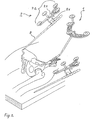
- Fig. 1 shows a iliac crest locator 1 with associated mounting bracket 3, which is mounted in the exposed area of the iliac crest.
- the mounting bracket 3 comprises a medial clamp part 3.1 and a lateral clamp part 3.2, which are screwed together via an Allen screw 5 until the mounting bracket is firmly seated on the iliac crest.
- the actual iliac crest locator 1 has a crescent-shaped body 1.1 with a Socket 1.2 for attachment to the mounting bracket 3 and a 4-point Lokatorfeld 1.3 of four IR-reflecting balls, which are each partially surrounded by a (not separately designated) spherical segment-shaped diffuser to avoid Störstrahlungseinflüssen.
- the multipoint transmitter 1 referred to above as the iliac crest locator, can also be fastened to the pan roof of the pelvis.
- This has the advantage that the above-mentioned (additional) incision in the area of the iliac crest becomes superfluous, but the attachment of the multi-point transmitter - which is then referred to as "surgical field locator" - less stable with weakened bone structure.
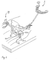
- FIG. 2 shows, in addition to the skeletal fixed locator 1 described above, a manual pushbutton 7 with a rod-shaped button part 9 tapering towards one end, from which a holder 9.1 protrudes vertically, an approximately Y-shaped pushbutton main body 7.1 and a 4-point Locator field 7.2, similar to the structure of the iliac crest locator described above.
- the locators of the arrangement components described below are constructed so that the corresponding designation of the parts and description thereof are omitted.
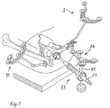
- Fig. 3 shows, in addition to the iliac crest locator 1, a femoral locator 11 with associated adapter (femoral clip) 13 for attachment near the proximal end of the femur.
- the femur clip 13 has a two-part main body of a bifurcated in plan view and in side view approximately L-shaped first base part 13.1, protrude from the two pins 13.2 for plugging the locator, and one with the first base part 13.1 latched, in the side view approximately L -shaped second base.
- the structure of the femur locator 11 itself corresponds - apart from an angled Lokatorstab - essentially that of the iliac crest locator.
- the femoral clamp 13 is fastened with the attached locator rod 15 on the lateral femoral side approximately at the level of the trochanter minor or between the trochanter minor and the greater trochanter by pushing the muscle groups lying there aside and inserting the clamp.
- the rotational position is to be chosen so that the locator rod projects laterally out of the surgical field, preferably in the direction of the camera.
- the clamp is tightened with medium torque, the actual (not separately designated) Lokatorfeld plugged and aligned to the camera and finally screwed the femur Lokator.
- the hip kinematic center of rotation in both the hip-fixed and femur-fixed coordinate systems is determined by several relative measurements of the femoral locator in the hip-fixed coordinate system at different leg positions.
- the transformation of all measured values can thus take place from the hip-fixed coordinate system into the coordinate system of the body axes. Allows all calibrated tools to be aligned to the body axis coordinate system; see below.
- With the center of rotation as the origin of the implant can be used at its kinematic origin. If corrections are required, shifts and angular changes in the planning can be performed intraoperatively.
- the femur locator is removed from the bracket 13 and the femoral head is resected.
- the diameter of the resected head is measured and, based on the measurement result, a suitable hemisphere is selected for the next step, namely the determination of the center of the acetabulum or geometric center of rotation of the hip.
- the selected hemisphere 17 is combined with a hand-held button 7 'of the type shown in FIG. 2 and described above to form a ball adapter / hand-button combination 19.
- this locator in the pan area (usually assuming a certain anteversion angle, eg 12 °) on the one hand, the validity of the determined by the femur locator (kinematic) center of rotation from a geometric perspective, and on the other hand allow the results of a "cross-check" to the implantation planning values under geometrical aspects.
- indications of possible mechanical collisions can be obtained.
- the construction of the half-shell and its adaptation to the hand-held push-button always realizes the tip of the probe in the ball center of the antispherical ball.
- the final planning of the implantation takes place, from the determination of the implant size to be used up to displacement values and angle values.
- the system calculates target positions for the resecting or setting instruments to be used or, more precisely, for their effective sections.
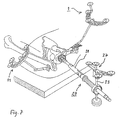
- FIG. 5 shows, in addition to the iliac crest and femur locators 1, 11, a milling cutter-locator combination 21 having a milling shaft 23, a milling shaft adapter 25 and a locator 27, the construction of which essentially corresponds to that of the femur locator 11 according to FIG.
- This instrument is aligned in a manner shown in the figure in a pan area, the position and orientation is detected due to the position signals from the Lokatorfeld and visually illustrated on screens in the manner shown in Fig. 6.
- a correct position of the milling cutter according to the planning data is indicated by a ring extending around the milling shaft in the display and by acoustic signals.
- the cutter-locator combination is converted to a setter-locator combination 29 as shown in FIG.
- the locator 27 is used, now in conjunction with a setting instrument shaft 31 and a shaft adapter 33.
- this instrument is in a largely analog for handling the cutter-locator combination and also shown on the PC screen a way Acetabulum 35 set. Their final position is entered into the system by the surgeon.
- the shaft preparation and implantation (initially a test shaft), either in a conventional or also supported by the navigation system way done. Height and anteversion of the shaft are fixed according to the planning data; only the ball neck length is still freely selectable. Then, the joint is assembled with the test shaft and stability and any collisions when moving the shaft in the pan checked. In addition, a rough examination of the leg length is done by comparing the position of the ankle of the operated leg of the healthy. If joint stability problems occur, an attempt will be made to solve them by selecting a particular ball or stem of a different size from a ready-made assortment.
- measurements can also be taken on the other leg using the navigation system, the results of which, in the sense of symmetry considerations, can be used to fine-tune the implant. It is understood that such measurements employ a femoral locator modified for external application over the skin instead of the femoral locator described above.
- An essential advantage of the proposed system is that, using navigation data, it is also possible to compare leg lengths (at the diseased hip before the operation and during the above-mentioned checking step in the final phase of the operation) before and after the leg length.
- leg lengths at the diseased hip before the operation and during the above-mentioned checking step in the final phase of the operation
- the femur locator is again positioned and fixed on the holder remaining on the femur and the position is detected with the leg extended and aligned parallel to the body longitudinal axis.
- the obtained position data provide evidence for any leg extension or leg shortening as well as for the so-called lateralization or medialization, ie the "lateral" position of the femur.
- a different stem may be used in conjunction with another ball, if appropriate, compared to the test stem; in any case give the However, measurements provide the physician with information that should be taken into account when continuing to care for the patient.
- the placement of the stem of a hip prosthesis requires the production of a planned anti-torsion angle of the femoral neck and the angular production of the original leg length.
- the axis alignment of the shaft depends largely on the position of the medullary canal in the femur. This has the consequence that only from this the actual stem size or its offsets can be calculated.
- the medullary canal of the femur is determined.
- Another important information for the placement of the stem is the determination of the center of rotation; see above.
- a navigation instrument To insert this navigation instrument, the proximal end of the femur is opened with a box chisel or a jigsaw in the vicinity of the greater trochanter and the medullary canal 39 is inserted there from the proximal end.
- the angle of inclination and the angle of antetorsion of the femoral head are determined in the X-ray image and entered intraoperatively.
- the intraoperative determination of the antetorsion angle is possible by measuring landmarks on the knee joint and on the upper ankle joint, whereby intraoperatively the body levels are known.
- the actual implantation angles and positions of cup navigation can be taken into account during stem implantation.
- the last spatial position of the pan can be considered relative correction the shaft are attached. This procedure ensures optimal implantation.
- the preparation of the femur for insertion of the shaft is then - analogous to the preparation of the socket seat with a navigated cutter - with a navigated sheep rasp, i. a Schaftraspel-Lokator combination, which is very similar to the combination shown in Fig. 8 and therefore neither shown nor described in detail here.
- a test shaft is again inserted and the checks described above in connection with the cup side navigation are carried out. With satisfactory results, the final shaft is then used, without this would have to be navigated again.
Claims (14)
- Dispositif de détermination peropératoire de la position et de l'orientation dans l'espace d'une prothèse articulaire, en particulier d'une cavité cotyloïde de la hanche ou de l'épaule ou d'une prothèse de diaphyse relative ou d'une prothèse de vertèbres, notamment d'une prothèse pour vertèbres lombaires ou cervicales, avec emploi d'un procédé de tomographie assistée par ordinateur, lequel comprend :- un dispositif de modélisation avec tomographie assistée par ordinateur pour la production et l'enregistrement d'une image en trois dimensions d'une zone articulaire ou vertébrale à équiper de la prothèse articulaire,- un dispositif optique de mesure des coordonnées pour la fourniture de coordonnées sur la position réelle de points définis réels ou virtuels de la zone articulaire ou vertébrale et/ou de vecteurs de relation positionnelle entre de tels points à l'intérieur de la zone articulaire ou vertébrale ou de ces points relatifs à la fonction articulaire à une extrémité, à l'extérieur de la zone articulaire ou vertébrale,sachant que le dispositif de mesure des coordonnées comprend une caméra stéréo ou un dispositif à caméra stéréo pour le captage spatial de signaux d'émission, au moins un émetteur multipoint, qui comporte un groupe de points de mesure reliés de manière fixe, et une unité d'analyse pour l'analyse de quantités de coordonnées des points de mesure fournies par le ou les émetteurs multipoint et relevées par la caméra stéréo et caractérisé par :- une unité de traitement avec matching pour l'adaptation, à la position réelle, de l'image à l'emplacement spatial actuel réel de la zone articulaire ou vertébrale au moyen des cordonnées de position réelle des points définis, sachant que l'unité de traitement avec matching est conçue pour le calcul de paramètres de transformation, avec minimisation des écarts de normales.
- Dispositif selon la revendication 1, caractérisé en ce que l'unité de traitement avec matching est conçue pour l'exécution d'un procédé de compensation interactif pour l'adaptation d'une surface osseuse palpée à une surface virtuelle correspondante de l'image avec utilisation combinée du principe du maillage des triangles et d'une approche spatiale « spline » avec la détermination des inconnues en tant que paramètres spline.
- Dispositif selon la revendication 1 ou 2,
caractérisé par une interface de saisie, pour la saisie de paramètres relatifs à la prothèse d'une quantité prédéterminée de prothèses pouvant être installées et pour la spécification de positions et d'orientations possibles pour la prothèse relativement à l'image, interface de saisie reliée au dispositif de modélisation avec tomographie assistée par ordinateur, réalisée en particulier sous la forme d'une interface utilisateur interactive avec des moyens de guidage de l'opérateur,
sachant que l'unité de traitement avec matching est reliée à l'interface de saisie et est conçue pour la détermination de coordonnées théoriques ou d'un vecteur de mouvement théorique de la prothèse à installer ainsi que d'une zone de résection ou d'un instrument de résection pour celui-ci à partir d'au moins un jeu de paramètres, de positions et d'orientations d'implantation saisis. - Dispositif selon la revendication 3,
caractérisé en ce que l'interface de saisie est conçue pour la saisie et l'intégration d'image des vecteurs des axes corporels pertinents et des paramètres de prothèse d'une cavité cotyloïde de la hanche, notamment des coordonnées du centre de rotation ainsi que de l'angle d'antéversion et de l'angle d'abduction. - Dispositif selon l'une quelconque des revendications précédentes, caractérisé en ce qu'un premier émetteur multipoint du dispositif de mesure des coordonnées est réalisé sous forme de palpeur mobile, guidé à la main, pour la palpation de références osseuses dans la zone articulaire ou vertébrale pour la détermination de leurs coordonnées.
- Dispositif selon l'une quelconque des revendications précédentes, caractérisé en ce qu'un second émetteur multipoint est conçu pour la fixation rigide à un os ou à une vertèbre dans la zone articulaire ou vertébrale.
- Dispositif selon l'une quelconque des revendications précédentes, caractérisé par :- un instrument de résection, notamment une fraise ou une lime, qui peut être assemblé de manière fixe au second émetteur multipoint ou à un troisième pour former une unité outil-émetteur pouvant naviguer, calibrée du point de vue géométrique, de telle sorte que, à partir des signaux d'émission de cette unité, il soit possible de déterminer des coordonnées de position réelle d'un segment actif de l'instrument de résection, notamment d'une tête de fraise ou d'un segment de lime, et, à partir de cela, au choix, des coordonnées de position réelle d'un segment de résection réalisé avec l'instrument de résection,- une configuration de l'interface de saisie pour la saisie de paramètres de l'instrument de résection qui permettent sa représentation synoptique avec l'image de la zone articulaire ou vertébrale, obtenue au moyen du dispositif de modélisation avec tomographie assistée par ordinateur,- une configuration de l'unité de traitement avec matching pour l'attribution des coordonnées de position réelle du segment actif et, au choix, des coordonnées de la position réelle du segment de résection à l'image de la zone articulaire ou vertébrale sensiblement en temps réel et- une unité graphique conçue pour la représentation synoptique du segment actif ou du segment de résection dans sa position actuelle avec l'image, adaptée aux coordonnées de position réelle, de la zone articulaire ou vertébrale.
- Dispositif selon l'une quelconque des revendications précédentes, caractérisé par :- un outil de montage, notamment un outil de vissage, qui peut être assemblé de manière fixe au second ou troisième émetteur multipoint pour former une unité outil-émetteur pouvant naviguer, calibrée du point de vue géométrique, de telle sorte que, à partir des signaux d'émission de cette unité, il soit possible de déterminer des coordonnées de position réelle d'un segment actif de l'outil de montage, notamment d'une lame de tournevis, et, ainsi, au choix, de la prothèse même,- une configuration de l'interface de saisie pour la saisie de paramètres de l'outil de montage qui permettent sa représentation synoptique avec l'image de la zone articulaire ou vertébrale, obtenue au moyen du dispositif de modélisation avec tomographie assistée par ordinateur,- une configuration de l'unité de traitement avec matching pour l'attribution des coordonnées de position réelle du segment actif et, au choix, de la prothèse à l'image de la zone articulaire ou vertébrale sensiblement en temps réel et- une unité graphique conçue pour la représentation synoptique du segment actif ou de la prothèse dans sa position réelle avec l'image de la zone articulaire ou vertébrale, adaptée aux coordonnées de position réelle.
- Dispositif selon la revendication 7 ou 8, caractérisé en ce que l'instrument de résection et/ou l'outil de montage est réalisé sous la forme d'un outil guidé à la main avec un manche, lequel comporte un segment de fixation pour l'assemblage fixe à l'émetteur multipoint.
- Dispositif selon l'une quelconque des revendications 1 à 7, caractérisé par :- une pièce d'adaptation pour la fixation rigide d'un émetteur multipoint à la prothèse articulaire, en particulier à l'extrémité proximale d'une prothèse de diaphyse, pour la formation d'une unité prothèse-émetteur pouvant naviguer de telle sorte qu'il soit possible de déterminer, à partir des signaux d'émission de cette unité, des coordonnées de position réelle de l'adaptateur et ainsi, au choix, de la prothèse même,- une configuration de l'interface de saisie pour la saisie de paramètres de l'adaptateur qui permettent la représentation synoptique de l'adaptateur ou de la prothèse avec l'image de la zone articulaire ou vertébrale, obtenue au moyen du dispositif de modélisation avec tomographie assistée par ordinateur,- une configuration de l'unité de traitement avec matching pour l'attribution des coordonnées de position réelle de l'adaptateur et, au choix, de la prothèse à l'image de la zone articulaire ou vertébrale sensiblement en temps réel et- une unité graphique conçue pour la représentation synoptique de l'adaptateur ou de la prothèse dans sa position réelle avec l'image de la zone articulaire ou vertébrale, adaptée aux coordonnées de position réelle.
- Dispositif selon l'une quelconque des revendications précédentes, caractérisé en ce que l'émetteur multipoint ou un émetteur multipoint minimal est réalisé sous la forme d'émetteur à quatre points passif comportant quatre segments à réflecteur sphérique et en ce qu'à la ou à une caméra stéréo est attribué de manière fixe, dans l'espace, un dispositif d'éclairage pour l'éclairage de l'émetteur multipoint ou des émetteurs multipoint.
- Dispositif selon l'une quelconque des revendications 2 à 11, caractérisé en ce que l'interface utilisateur comporte des moyens pour la réalisation d'un guidage par menu au moins pour l'orientation de l'image en trois dimensions par rapport aux axes corporels pertinents.
- Dispositif selon la revendication 12, caractérisé en ce que l'interface utilisateur comporte une mémoire multizone pour l'enregistrement des paramètres des prothèses pouvant être installées ou une interface de base de données relative à une base de données des paramètres de la prothèse et que les moyens de réalisation d'un guidage par menu sont conçus pour la réalisation d'un processus interactif de sélection d'une composante avec accès multiple à la mémoire multizone ou à la base de données des paramètres de prothèse.
- Dispositif selon l'une quelconque des revendications 3 à 13, caractérisé par une unité de production de signaux de commande reliée à l'unité d'analyse et à l'unité de traitement avec matching qui est conçue pour la comparaison d'un jeu de données sur la position ou l'orientation de la prothèse, saisies par le biais de l'interface de saisie et adaptées aux coordonnées de la position réelle de la zone articulaire ou vertébrale à des coordonnées de position réelle actuellement relevées du segment actif de l'instrument de résection ou de l'outil de montage ou de la prothèse et pour la détermination d'une différence entre des coordonnées de la position théorique et réelle et pour l'émission de données de différence ou d'un ordre de commande découlant de la différence, en particulier par sortie écrite ou vocale et/ou suivant une représentation synoptique avec image.
Applications Claiming Priority (5)
| Application Number | Priority Date | Filing Date | Title |
|---|---|---|---|
| DE10222415 | 2002-05-21 | ||
| DE10222415 | 2002-05-21 | ||
| DE10306793A DE10306793A1 (de) | 2002-05-21 | 2003-02-18 | Anordnung und Verfahren zur intraoperativen Festlegung der Lage eines Gelenkersatzimplantats |
| DE10306793 | 2003-02-18 | ||
| PCT/EP2003/004469 WO2003096870A2 (fr) | 2002-05-21 | 2003-04-29 | Dispositif et procede de fixation intra-operatoire de l'emplacement d'un implant d'articulation artificielle |
Publications (2)
| Publication Number | Publication Date |
|---|---|
| EP1507472A2 EP1507472A2 (fr) | 2005-02-23 |
| EP1507472B1 true EP1507472B1 (fr) | 2007-11-14 |
Family
ID=29550936
Family Applications (1)
| Application Number | Title | Priority Date | Filing Date |
|---|---|---|---|
| EP03752717A Expired - Lifetime EP1507472B1 (fr) | 2002-05-21 | 2003-04-29 | Dispositif de fixation intra-operatoire de l'emplacement d'un implant d'articulation artificielle |
Country Status (7)
| Country | Link |
|---|---|
| US (1) | US20050149050A1 (fr) |
| EP (1) | EP1507472B1 (fr) |
| JP (1) | JP4372000B2 (fr) |
| AT (1) | ATE378000T1 (fr) |
| AU (1) | AU2003242528A1 (fr) |
| DE (2) | DE10306793A1 (fr) |
| WO (1) | WO2003096870A2 (fr) |
Families Citing this family (110)
| Publication number | Priority date | Publication date | Assignee | Title |
|---|---|---|---|---|
| WO2002017798A1 (fr) * | 2000-08-31 | 2002-03-07 | Plus Endoprothetik Ag | Procede et dispositif de determination d'un axe de charge d'une extremite |
| US7708741B1 (en) * | 2001-08-28 | 2010-05-04 | Marctec, Llc | Method of preparing bones for knee replacement surgery |
| US9308002B2 (en) | 2002-11-07 | 2016-04-12 | Crescent H Trust | Precise hip component positioning for hip replacement surgery |
| US9610092B2 (en) | 2011-08-29 | 2017-04-04 | Microsoft Orthopedics Holdings Inc. | Precision hip replacement method |
| US20040171930A1 (en) * | 2003-02-04 | 2004-09-02 | Zimmer Technology, Inc. | Guidance system for rotary surgical instrument |
| US20040152955A1 (en) * | 2003-02-04 | 2004-08-05 | Mcginley Shawn E. | Guidance system for rotary surgical instrument |
| US7862570B2 (en) | 2003-10-03 | 2011-01-04 | Smith & Nephew, Inc. | Surgical positioners |
| US7764985B2 (en) | 2003-10-20 | 2010-07-27 | Smith & Nephew, Inc. | Surgical navigation system component fault interfaces and related processes |
| WO2005048851A1 (fr) | 2003-11-14 | 2005-06-02 | Smith & Nephew, Inc. | Systemes coupants ajustables de chirurgie |
| US20050109855A1 (en) * | 2003-11-25 | 2005-05-26 | Mccombs Daniel | Methods and apparatuses for providing a navigational array |
| US8419798B2 (en) | 2003-12-30 | 2013-04-16 | Depuy Products, Inc. | Joint prosthesis with infinitely positionable head |
| US20050203539A1 (en) * | 2004-03-08 | 2005-09-15 | Grimm James E. | Navigated stemmed orthopaedic implant inserter |
| DE102004013368A1 (de) * | 2004-03-17 | 2005-10-06 | Merete Medical Gmbh | Modulares Gelenkprothesensystem |
| EP1729665A1 (fr) * | 2004-03-31 | 2006-12-13 | Smith and Nephew, Inc. | Procedes et dispositifs pour l'etablissement d'un dispositif d'entree de reseau de reference |
| WO2005104978A1 (fr) | 2004-04-21 | 2005-11-10 | Smith & Nephew, Inc. | Procedes, systemes et appareils assistes par ordinateur pour arthroplastie de l'epaule |
| DE102004042183A1 (de) | 2004-06-22 | 2006-01-19 | Plus Endoprothetik Ag | Gerät zum Setzen oder Entfernen von Gelenken oder Gelenkpfannen |
| US8273093B2 (en) | 2004-06-29 | 2012-09-25 | Depuy Products, Inc. | Instrumentation for recording and replicating orthopaedic implant orientation |
| US7636595B2 (en) * | 2004-10-28 | 2009-12-22 | Medtronic Navigation, Inc. | Method and apparatus for calibrating non-linear instruments |
| EP1654997B1 (fr) * | 2004-11-08 | 2007-12-12 | BrainLAB AG | Adaptation de la longueur de la jambe dans la pose d'une prothèse de la hanche |
| US20060190011A1 (en) * | 2004-12-02 | 2006-08-24 | Michael Ries | Systems and methods for providing a reference plane for mounting an acetabular cup during a computer-aided surgery |
| US8460390B2 (en) | 2004-12-29 | 2013-06-11 | Depuy Products, Inc. | System and method for replicating orthopaedic implant orientation |
| US8444698B2 (en) | 2004-12-29 | 2013-05-21 | Depuy Products, Inc. | Joint prosthesis with infinitely positionable head |
| DE102005003317A1 (de) * | 2005-01-17 | 2006-07-27 | Aesculap Ag & Co. Kg | Verfahren zur Bestimmung der neutralen Position eines Oberschenkelknochens relativ zu einem Beckenknochen und Vorrichtung zur Durchführung dieses Verfahrens |
| DE102005003318A1 (de) * | 2005-01-17 | 2006-07-27 | Aesculap Ag & Co. Kg | Verfahren zur Anzeige der Position und Orientierung eines chirurgischen Werkzeuges und Vorrichtung zur Durchführung dieses Verfahrens |
| JP2008531091A (ja) | 2005-02-22 | 2008-08-14 | スミス アンド ネフュー インコーポレーテッド | 直列型ミリングシステム |
| KR100706030B1 (ko) * | 2005-04-12 | 2007-04-11 | 한국과학기술원 | 참조기구를 이용한 비구컵 항행장치 및 이를 이용한 비구컵항행방법 |
| DE102005030184B4 (de) * | 2005-06-29 | 2008-09-11 | Aesculap Ag & Co. Kg | Verfahren zur Bestimmung der Relativposition eines Markierelementes an einem chirurgischen Instrument sowie chirurgisches Instrument und Navigationssystem zur Durchführung dieses Verfahrens |
| US8679185B2 (en) | 2005-09-30 | 2014-03-25 | DePuy Synthes Products, LLC | Joint prosthesis with positionable head |
| DE502005004417D1 (de) * | 2005-10-12 | 2008-07-24 | Brainlab Ag | Marker für ein Navigationssystem und Verfahren zum Detektieren eines Markers |
| DE602005012836D1 (de) * | 2005-10-25 | 2009-04-02 | Brainlab Ag | Nichteindringende Befestigungsvorrichtung |
| US8192449B2 (en) * | 2005-10-25 | 2012-06-05 | Brainlab Ag | Non-penetrating fixing device |
| US7525309B2 (en) | 2005-12-30 | 2009-04-28 | Depuy Products, Inc. | Magnetic sensor array |
| US8862200B2 (en) | 2005-12-30 | 2014-10-14 | DePuy Synthes Products, LLC | Method for determining a position of a magnetic source |
| US20070161888A1 (en) * | 2005-12-30 | 2007-07-12 | Sherman Jason T | System and method for registering a bone of a patient with a computer assisted orthopaedic surgery system |
| US20070239153A1 (en) * | 2006-02-22 | 2007-10-11 | Hodorek Robert A | Computer assisted surgery system using alternative energy technology |
| DE102006035602A1 (de) * | 2006-07-31 | 2008-02-07 | Plus Orthopedics Ag | Klammer zur Befestigung chirurgischer Operationshilfsmittel, Stellorgan für eine derartige Klammer und eine Anordnung umfassend ein Stellorgan und eine Klammer |
| CA2679369A1 (fr) * | 2006-11-17 | 2008-05-29 | Smith & Nephew, Inc. | Fixation de cadre de reference |
| EP1929964B1 (fr) * | 2006-12-05 | 2009-10-21 | BrainLAB AG | Support pour instrument de perçage et système de fixation de cet instrument |
| US8475470B2 (en) * | 2006-12-21 | 2013-07-02 | General Electric Company | Percutaneous registration apparatus and method for use in surgical navigation |
| US8068648B2 (en) | 2006-12-21 | 2011-11-29 | Depuy Products, Inc. | Method and system for registering a bone of a patient with a computer assisted orthopaedic surgery system |
| US8357165B2 (en) | 2006-12-22 | 2013-01-22 | Depuy Products, Inc. | Reference array mounting bracket for use with a computer assisted orthopaedic surgery system |
| WO2008105874A1 (fr) * | 2007-02-28 | 2008-09-04 | Smith & Nephew, Inc. | Implant orthopédique instrumenté pour identifier un repère |
| US8784425B2 (en) | 2007-02-28 | 2014-07-22 | Smith & Nephew, Inc. | Systems and methods for identifying landmarks on orthopedic implants |
| DE102007051719A1 (de) * | 2007-10-30 | 2009-05-07 | Sicat Gmbh & Co. Kg | Schichtaufnahmen zur Implantatplanung |
| US8267938B2 (en) | 2007-11-01 | 2012-09-18 | Murphy Stephen B | Method and apparatus for determining acetabular component positioning |
| US10335236B1 (en) | 2007-11-01 | 2019-07-02 | Stephen B. Murphy | Surgical system using a registration device |
| US8986309B1 (en) * | 2007-11-01 | 2015-03-24 | Stephen B. Murphy | Acetabular template component and method of using same during hip arthrosplasty |
| US9220514B2 (en) * | 2008-02-28 | 2015-12-29 | Smith & Nephew, Inc. | System and method for identifying a landmark |
| GB0803725D0 (en) * | 2008-02-29 | 2008-04-09 | Depuy Int Ltd | Surgical apparatus and procedure |
| US8828008B2 (en) | 2008-03-05 | 2014-09-09 | Allston J. Stubbs | Apparatus for arthroscopic assisted arthroplasty of the hip joint |
| US8549888B2 (en) | 2008-04-04 | 2013-10-08 | Nuvasive, Inc. | System and device for designing and forming a surgical implant |
| US8002838B2 (en) | 2008-06-11 | 2011-08-23 | Depuy Products, Inc. | Joint prosthesis with positionable head |
| WO2010063117A1 (fr) | 2008-12-02 | 2010-06-10 | Andre Novomir Hladio | Procédé et système d'alignement d'une prothèse à l'aide de détecteurs actifs lors d'une chirurgie |
| US9031637B2 (en) | 2009-04-27 | 2015-05-12 | Smith & Nephew, Inc. | Targeting an orthopaedic implant landmark |
| US8945147B2 (en) * | 2009-04-27 | 2015-02-03 | Smith & Nephew, Inc. | System and method for identifying a landmark |
| GB0913930D0 (en) * | 2009-08-07 | 2009-09-16 | Ucl Business Plc | Apparatus and method for registering two medical images |
| US20110060339A1 (en) * | 2009-09-09 | 2011-03-10 | De Wekker Erwin | Hip surgery assembly |
| ES2425547T3 (es) | 2010-03-25 | 2013-10-16 | Hipsecure B.V. | Sistema de navegación para cirugía ortopédica |
| WO2011131223A1 (fr) * | 2010-04-19 | 2011-10-27 | Brainlab Ag | Procédé de traitement et de transfert de données lié à la mise en place d'implants chirurgicaux |
| WO2011153468A2 (fr) | 2010-06-03 | 2011-12-08 | Smith & Nephew, Inc. | Implants orthopédiques |
| CA2821110A1 (fr) * | 2010-12-13 | 2012-06-21 | Ortho Kinematics, Inc. | Procedes, systemes et dispositifs de rapport de donnees cliniques et de navigation chirurgicale |
| CN103402450A (zh) | 2010-12-17 | 2013-11-20 | 阿韦尼尔医药公司 | 用于在外科手术中对准假体的方法及系统 |
| US8890511B2 (en) | 2011-01-25 | 2014-11-18 | Smith & Nephew, Inc. | Targeting operation sites |
| CA2834940A1 (fr) | 2011-05-06 | 2012-11-15 | Smith & Nephew, Inc. | Ciblage de points de repere de dispositifs orthopediques |
| BR112013032144A2 (pt) | 2011-06-16 | 2016-12-13 | Smith & Nephew Inc | alinhamento cirúrgico utilizando referências |
| WO2012171577A1 (fr) * | 2011-06-17 | 2012-12-20 | Brainlab Ag | Procédé, système et dispositif de positionnement d'un implant |
| US9167989B2 (en) * | 2011-09-16 | 2015-10-27 | Mako Surgical Corp. | Systems and methods for measuring parameters in joint replacement surgery |
| DE102011119073A1 (de) * | 2011-11-15 | 2013-05-16 | Fiagon Gmbh | Registrierverfahren, Positionserfassungssystem und Abtastinstrument |
| US11207132B2 (en) | 2012-03-12 | 2021-12-28 | Nuvasive, Inc. | Systems and methods for performing spinal surgery |
| US9314188B2 (en) | 2012-04-12 | 2016-04-19 | Intellijoint Surgical Inc. | Computer-assisted joint replacement surgery and navigation systems |
| US10092218B2 (en) | 2012-07-30 | 2018-10-09 | Orthosoft, Inc. | Pelvic digitizer device with inertial sensor unit and method |
| US9646229B2 (en) | 2012-09-28 | 2017-05-09 | Siemens Medical Solutions Usa, Inc. | Method and system for bone segmentation and landmark detection for joint replacement surgery |
| CA2890212A1 (fr) | 2012-11-09 | 2014-05-15 | Blue Belt Technologies, Inc. | Systemes et procedes de navigation et de commande d'un dispositif de positionnement d'implant |
| EP3424459B1 (fr) | 2013-01-16 | 2023-12-13 | Stryker Corporation | Système de navigation pour indiquer et réduire des erreurs de ligne de vue |
| US9993273B2 (en) | 2013-01-16 | 2018-06-12 | Mako Surgical Corp. | Bone plate and tracking device using a bone plate for attaching to a patient's anatomy |
| US9247998B2 (en) | 2013-03-15 | 2016-02-02 | Intellijoint Surgical Inc. | System and method for intra-operative leg position measurement |
| US9585768B2 (en) | 2013-03-15 | 2017-03-07 | DePuy Synthes Products, Inc. | Acetabular cup prosthesis alignment system and method |
| EP3007636B1 (fr) | 2013-06-11 | 2017-09-27 | Minmaxmedical | Système pour le traitement d'un volume planifié d'une partie de corps |
| KR101535233B1 (ko) * | 2013-09-16 | 2015-07-09 | 한양대학교 산학협력단 | 뇌수술용 다자유도 구동방법 |
| FR3010628B1 (fr) | 2013-09-18 | 2015-10-16 | Medicrea International | Procede permettant de realiser la courbure ideale d'une tige d'un materiel d'osteosynthese vertebrale destinee a etayer la colonne vertebrale d'un patient |
| US9848922B2 (en) | 2013-10-09 | 2017-12-26 | Nuvasive, Inc. | Systems and methods for performing spine surgery |
| FR3012030B1 (fr) | 2013-10-18 | 2015-12-25 | Medicrea International | Procede permettant de realiser la courbure ideale d'une tige d'un materiel d'osteosynthese vertebrale destinee a etayer la colonne vertebrale d'un patient |
| DE102013222230A1 (de) | 2013-10-31 | 2015-04-30 | Fiagon Gmbh | Chirurgisches Instrument |
| KR101594989B1 (ko) * | 2014-05-30 | 2016-02-18 | 큐렉소 주식회사 | 조직 위치 정합 방법 및 이를 이용하는 장치 |
| US10433893B1 (en) | 2014-10-17 | 2019-10-08 | Nuvasive, Inc. | Systems and methods for performing spine surgery |
| US20160262800A1 (en) * | 2015-02-13 | 2016-09-15 | Nuvasive, Inc. | Systems and methods for planning, performing, and assessing spinal correction during surgery |
| US20160354161A1 (en) * | 2015-06-05 | 2016-12-08 | Ortho Kinematics, Inc. | Methods for data processing for intra-operative navigation systems |
| US10456211B2 (en) | 2015-11-04 | 2019-10-29 | Medicrea International | Methods and apparatus for spinal reconstructive surgery and measuring spinal length and intervertebral spacing, tension and rotation |
| EP3417776A4 (fr) * | 2016-02-15 | 2019-07-10 | Keio University | Appareil, procédé et programme d'évaluation de l'alignement de la colonne vertébrale |
| CN105769393A (zh) * | 2016-04-08 | 2016-07-20 | 罗佳 | 一种髋关节假体匹配方法及系统 |
| US10537395B2 (en) | 2016-05-26 | 2020-01-21 | MAKO Surgical Group | Navigation tracker with kinematic connector assembly |
| AU2017319515B2 (en) * | 2016-08-30 | 2019-11-21 | Mako Surgical Corp. | Systems and methods for intra-operative pelvic registration |
| WO2018067794A1 (fr) | 2016-10-05 | 2018-04-12 | Nuvasive, Inc. | Système de navigation chirurgicale et procédés associés |
| WO2018109556A1 (fr) | 2016-12-12 | 2018-06-21 | Medicrea International | Systèmes et procédés pour des implants rachidiens spécifiques au patient |
| WO2018193317A1 (fr) | 2017-04-21 | 2018-10-25 | Medicrea International | Système de suivi intra-opératoire pour assister la chirurgie rachidienne |
| US11033341B2 (en) | 2017-05-10 | 2021-06-15 | Mako Surgical Corp. | Robotic spine surgery system and methods |
| EP3621545B1 (fr) | 2017-05-10 | 2024-02-21 | MAKO Surgical Corp. | Système robotique d'opération chirurgicale de la colonne vertébrale |
| US10918422B2 (en) | 2017-12-01 | 2021-02-16 | Medicrea International | Method and apparatus for inhibiting proximal junctional failure |
| WO2019137507A1 (fr) * | 2018-01-11 | 2019-07-18 | Shenzhen United Imaging Healthcare Co., Ltd. | Systèmes et procédés de planification de voie chirurgicale |
| CN108158655A (zh) * | 2018-01-25 | 2018-06-15 | 上海长征医院 | 用于颈椎前路手术的导航定位器固定装置 |
| JP2021511866A (ja) | 2018-01-26 | 2021-05-13 | マコ サージカル コーポレーション | 手術ロボットで案内されたプロテーゼ嵌入のためのエンドエフェクタおよびシステム |
| KR102166149B1 (ko) | 2019-03-13 | 2020-10-15 | 큐렉소 주식회사 | 페디클 스크류 고정 플래닝 시스템 및 방법 |
| US11925417B2 (en) | 2019-04-02 | 2024-03-12 | Medicrea International | Systems, methods, and devices for developing patient-specific spinal implants, treatments, operations, and/or procedures |
| US11877801B2 (en) | 2019-04-02 | 2024-01-23 | Medicrea International | Systems, methods, and devices for developing patient-specific spinal implants, treatments, operations, and/or procedures |
| EP3719749A1 (fr) | 2019-04-03 | 2020-10-07 | Fiagon AG Medical Technologies | Procédé et configuration d'enregistrement |
| US11612440B2 (en) | 2019-09-05 | 2023-03-28 | Nuvasive, Inc. | Surgical instrument tracking devices and related methods |
| US11769251B2 (en) | 2019-12-26 | 2023-09-26 | Medicrea International | Systems and methods for medical image analysis |
| USD995790S1 (en) | 2020-03-30 | 2023-08-15 | Depuy Ireland Unlimited Company | Robotic surgical tool |
| CN113681895B (zh) * | 2021-08-20 | 2023-03-10 | 宜宾显微智能科技有限公司 | 一种导针定位导向板定制及模拟验证系统及其方法 |
| CN113768640B (zh) * | 2021-11-09 | 2022-02-08 | 极限人工智能有限公司 | 一种确定机械臂工作位姿的方法和装置 |
Family Cites Families (39)
| Publication number | Priority date | Publication date | Assignee | Title |
|---|---|---|---|---|
| US4759350A (en) * | 1986-10-17 | 1988-07-26 | Dunn Harold K | Instruments for shaping distal femoral and proximal tibial surfaces |
| US4979949A (en) * | 1988-04-26 | 1990-12-25 | The Board Of Regents Of The University Of Washington | Robot-aided system for surgery |
| US5007912A (en) * | 1990-05-30 | 1991-04-16 | Albrektsson Bjoern | Arrangement for fixing a knee-joint in defined positions and for positional control of instruments for replacing the knee-joint with a prosthesis |
| US5198877A (en) * | 1990-10-15 | 1993-03-30 | Pixsys, Inc. | Method and apparatus for three-dimensional non-contact shape sensing |
| US5198977A (en) * | 1990-11-27 | 1993-03-30 | Jesse Salb | System and method for localization of functional activity in the human brain |
| US6006126A (en) * | 1991-01-28 | 1999-12-21 | Cosman; Eric R. | System and method for stereotactic registration of image scan data |
| US5265034A (en) * | 1991-05-13 | 1993-11-23 | The United States Of America As Represented By The Administrator Of The National Aeronautics And Space Administration | Feedback controlled optics with wavefront compensation |
| US5514143A (en) * | 1991-11-27 | 1996-05-07 | Apogee Medical Products, Inc. | Apparatus and method for use during surgery |
| AU680267B2 (en) * | 1993-06-21 | 1997-07-24 | Howmedica Osteonics Corp. | Method and apparatus for locating functional structures of the lower leg during knee surgery |
| WO1995000076A1 (fr) * | 1993-06-21 | 1995-01-05 | Osteonics Corp. | Appareil et procede permettant d'aligner des protheses du genou |
| US5601566A (en) * | 1994-02-22 | 1997-02-11 | Osteonics Corp. | Method and apparatus for the alignment of a femoral knee prosthesis |
| US5910143A (en) * | 1994-12-16 | 1999-06-08 | Exactech, Inc. | Intramedullary alignment guide tool |
| FR2734900B1 (fr) * | 1995-06-01 | 1997-07-04 | Sextant Avionique | Procede de determination de la position et de l'orientation d'un systeme mobile, notamment de la ligne de visee dans un viseur de casque |
| US5806518A (en) * | 1995-09-11 | 1998-09-15 | Integrated Surgical Systems | Method and system for positioning surgical robot |
| US6351659B1 (en) * | 1995-09-28 | 2002-02-26 | Brainlab Med. Computersysteme Gmbh | Neuro-navigation system |
| US5682886A (en) * | 1995-12-26 | 1997-11-04 | Musculographics Inc | Computer-assisted surgical system |
| US5880976A (en) * | 1997-02-21 | 1999-03-09 | Carnegie Mellon University | Apparatus and method for facilitating the implantation of artificial components in joints |
| DE29704393U1 (de) * | 1997-03-11 | 1997-07-17 | Aesculap Ag | Vorrichtung zur präoperativen Bestimmung der Positionsdaten von Endoprothesenteilen |
| US5888245A (en) * | 1997-05-21 | 1999-03-30 | Bristol-Myers Squibb Company | Rotational alignment guide for a prosthetic hip stem implant and method of using same |
| WO1999023956A1 (fr) * | 1997-11-05 | 1999-05-20 | Synthes Ag, Chur | Representation virtuelle d'un os ou d'une articulation |
| DE19805314A1 (de) * | 1998-02-10 | 1999-08-19 | Patent Treuhand Ges Fuer Elektrische Gluehlampen Mbh | Schaltungsanordnung zum Betrieb mindestens einer elektrodenlosen Entladungslampe |
| US6554837B1 (en) * | 1998-06-29 | 2003-04-29 | Plus Endoprothetik Ag | Device and method for inserting a prosthetic knee |
| US6327491B1 (en) * | 1998-07-06 | 2001-12-04 | Neutar, Llc | Customized surgical fixture |
| US6013081A (en) * | 1998-09-09 | 2000-01-11 | Sulzer Orthopedics Inc. | Apparatus and method for anterior and posterior referenced sizing and distal femur resection |
| FR2785517B1 (fr) * | 1998-11-10 | 2001-03-09 | Univ Joseph Fourier | Procede et dispositif de determination du centre d'une articulation |
| US6692447B1 (en) * | 1999-02-16 | 2004-02-17 | Frederic Picard | Optimizing alignment of an appendicular |
| WO2000054687A1 (fr) * | 1999-03-17 | 2000-09-21 | Synthes Ag Chur | Dispositif d'imagerie et de planification permettant la mise en place d'une greffe ligamentaire |
| WO2000063645A1 (fr) * | 1999-04-19 | 2000-10-26 | Leica Geosystems Ag | Determination de position indirecte au moins d'un dispositif de poursuite |
| FR2799112B1 (fr) * | 1999-10-01 | 2002-07-19 | Praxim | Procede de recalage d'images medicales sur un patient et dispositif associe |
| US6711432B1 (en) * | 2000-10-23 | 2004-03-23 | Carnegie Mellon University | Computer-aided orthopedic surgery |
| WO2002017798A1 (fr) * | 2000-08-31 | 2002-03-07 | Plus Endoprothetik Ag | Procede et dispositif de determination d'un axe de charge d'une extremite |
| WO2003068090A1 (fr) * | 2002-02-11 | 2003-08-21 | Smith & Nephew, Inc. | Reduction de fracture guidee par image |
| AU2003215562A1 (en) * | 2002-05-21 | 2003-12-02 | Plus Endoprothetik Ag | Arrangement for determining function-determined geometric variables of a joint of a vertebrate |
| EP1558150B1 (fr) * | 2002-11-05 | 2006-03-22 | Aesculap AG & Co. KG | Dispositif pour determiner la position d'une endoprothese du genou |
| US7318827B2 (en) * | 2002-12-02 | 2008-01-15 | Aesculap Ag & Co. Kg | Osteotomy procedure |
| DE20303499U1 (de) * | 2003-02-26 | 2003-04-30 | Aesculap Ag & Co Kg | Patella-Referenzvorrichtung |
| DE10343826B4 (de) * | 2003-09-22 | 2006-02-09 | Plus-Endoprothetik Ag | Knochenfester Lokator und Navigationssystem |
| DE502004009884D1 (de) * | 2004-02-03 | 2009-09-24 | Brainlab Ag | Vorrichtung zum Bestimmen der Position eines Schneidblocks |
| EP1616540B1 (fr) * | 2004-07-14 | 2007-11-14 | BrainLAB AG | Système de positionnement avec un implant cannelé |
-
2003
- 2003-02-18 DE DE10306793A patent/DE10306793A1/de not_active Withdrawn
- 2003-04-29 JP JP2004504878A patent/JP4372000B2/ja not_active Expired - Fee Related
- 2003-04-29 DE DE50308602T patent/DE50308602D1/de not_active Expired - Lifetime
- 2003-04-29 AU AU2003242528A patent/AU2003242528A1/en not_active Abandoned
- 2003-04-29 WO PCT/EP2003/004469 patent/WO2003096870A2/fr active IP Right Grant
- 2003-04-29 AT AT03752717T patent/ATE378000T1/de not_active IP Right Cessation
- 2003-04-29 EP EP03752717A patent/EP1507472B1/fr not_active Expired - Lifetime
-
2004
- 2004-11-19 US US10/994,188 patent/US20050149050A1/en not_active Abandoned
Also Published As
| Publication number | Publication date |
|---|---|
| ATE378000T1 (de) | 2007-11-15 |
| DE10306793A1 (de) | 2003-12-04 |
| AU2003242528A8 (en) | 2003-12-02 |
| JP2005525858A (ja) | 2005-09-02 |
| DE50308602D1 (de) | 2007-12-27 |
| EP1507472A2 (fr) | 2005-02-23 |
| AU2003242528A1 (en) | 2003-12-02 |
| JP4372000B2 (ja) | 2009-11-25 |
| WO2003096870A3 (fr) | 2004-09-02 |
| US20050149050A1 (en) | 2005-07-07 |
| WO2003096870A2 (fr) | 2003-11-27 |
Similar Documents
| Publication | Publication Date | Title |
|---|---|---|
| EP1507472B1 (fr) | Dispositif de fixation intra-operatoire de l'emplacement d'un implant d'articulation artificielle | |
| EP1507488B1 (fr) | Ensemble permettant de determiner des dimensions geometriques, a definition de fonction, d'une articulation d'un vertebre | |
| DE112005002453B4 (de) | System und Verfahren zum Durchführen einer Arthroplastik eines Gelenks und zum Verfolgen einer senkrechten Ebene | |
| EP3322337B1 (fr) | Procédé mis en oeuvre par ordinateur de calcul de la longueur de la jambe sur la base des extrémités inférieures | |
| US10441437B2 (en) | System for determining the position of a knee prosthesis | |
| JP7280967B2 (ja) | 手術位置合わせ用のシステム及び方法 | |
| EP3012759B1 (fr) | Procédé de planification, de préparation, de suivi, de surveillance et/ou de contrôle final d'une intervention opératoire dans les corps humains ou d'animaux, procédé d'exécution d'une telle intervention et utilisation du dispositif | |
| Hofstetter et al. | Computer-assisted fluoroscopy-based reduction of femoral fractures and antetorsion correction | |
| Paul et al. | Development of a surgical robot for cementless total hip arthroplasty | |
| Zheng et al. | A hybrid CT-free navigation system for total hip arthroplasty | |
| US5007936A (en) | Surgical method for hip joint replacement | |
| EP1893138B1 (fr) | Implantation de cotyle prothetique | |
| US5824085A (en) | System and method for cavity generation for surgical planning and initial placement of a bone prosthesis | |
| JP5918356B2 (ja) | 患者特有の寛骨臼調整ガイド | |
| US9220510B2 (en) | System and method for bone preparation for an implant | |
| EP1628590B1 (fr) | Methode de determination d'un systeme coordonne pour l'arthroplastie totale de la hanche | |
| EP1313400B1 (fr) | Dispositif de determination d'un axe de charge d'une extremite | |
| DE60319330T2 (de) | Chirurgisches Instrument | |
| US11478362B2 (en) | Robotic surgery system for augmented hip arthroplasty procedures | |
| WO2002062250A1 (fr) | Procede et dispositif de navigation peroperatoire | |
| EP1654997B1 (fr) | Adaptation de la longueur de la jambe dans la pose d'une prothèse de la hanche | |
| Fadda et al. | Computer and Robot Assisted Total Knee Arthroplasty | |
| DE102015205214A1 (de) | Verfahren für ein integriertes Operations-Planungs- und Unterstützungs-System für Operationen am menschlichen oder tierischen Körper sowie eine Vorrichtung hierfür |
Legal Events
| Date | Code | Title | Description |
|---|---|---|---|
| PUAI | Public reference made under article 153(3) epc to a published international application that has entered the european phase |
Free format text: ORIGINAL CODE: 0009012 |
|
| 17P | Request for examination filed |
Effective date: 20041102 |
|
| AK | Designated contracting states |
Kind code of ref document: A2 Designated state(s): AT BE BG CH CY CZ DE DK EE ES FI FR GB GR HU IE IT LI LU MC NL PT RO SE SI SK TR |
|
| AX | Request for extension of the european patent |
Extension state: AL LT LV MK |
|
| DAX | Request for extension of the european patent (deleted) | ||
| RAP1 | Party data changed (applicant data changed or rights of an application transferred) |
Owner name: PLUS ORTHOPEDICS AG |
|
| 17Q | First examination report despatched |
Effective date: 20061219 |
|
| GRAP | Despatch of communication of intention to grant a patent |
Free format text: ORIGINAL CODE: EPIDOSNIGR1 |
|
| RTI1 | Title (correction) |
Free format text: ARRANGEMENT FOR INTEROPERATIVE DETERMINATION OF THE POSITION OF AN ARTICULAR JOINT REPLACEMENT IMPLANT |
|
| GRAS | Grant fee paid |
Free format text: ORIGINAL CODE: EPIDOSNIGR3 |
|
| GRAA | (expected) grant |
Free format text: ORIGINAL CODE: 0009210 |
|
| AK | Designated contracting states |
Kind code of ref document: B1 Designated state(s): AT BE BG CH CY CZ DE DK EE ES FI FR GB GR HU IE IT LI LU MC NL PT RO SE SI SK TR |
|
| REG | Reference to a national code |
Ref country code: GB Ref legal event code: FG4D Free format text: NOT ENGLISH |
|
| REG | Reference to a national code |
Ref country code: CH Ref legal event code: EP |
|
| REG | Reference to a national code |
Ref country code: IE Ref legal event code: FG4D Free format text: LANGUAGE OF EP DOCUMENT: GERMAN |
|
| REF | Corresponds to: |
Ref document number: 50308602 Country of ref document: DE Date of ref document: 20071227 Kind code of ref document: P |
|
| REG | Reference to a national code |
Ref country code: CH Ref legal event code: NV Representative=s name: TROESCH SCHEIDEGGER WERNER AG |
|
| PG25 | Lapsed in a contracting state [announced via postgrant information from national office to epo] |
Ref country code: NL Free format text: LAPSE BECAUSE OF FAILURE TO SUBMIT A TRANSLATION OF THE DESCRIPTION OR TO PAY THE FEE WITHIN THE PRESCRIBED TIME-LIMIT Effective date: 20071114 Ref country code: SE Free format text: LAPSE BECAUSE OF FAILURE TO SUBMIT A TRANSLATION OF THE DESCRIPTION OR TO PAY THE FEE WITHIN THE PRESCRIBED TIME-LIMIT Effective date: 20080214 Ref country code: ES Free format text: LAPSE BECAUSE OF FAILURE TO SUBMIT A TRANSLATION OF THE DESCRIPTION OR TO PAY THE FEE WITHIN THE PRESCRIBED TIME-LIMIT Effective date: 20080225 |
|
| NLV1 | Nl: lapsed or annulled due to failure to fulfill the requirements of art. 29p and 29m of the patents act | ||
| PG25 | Lapsed in a contracting state [announced via postgrant information from national office to epo] |
Ref country code: SI Free format text: LAPSE BECAUSE OF FAILURE TO SUBMIT A TRANSLATION OF THE DESCRIPTION OR TO PAY THE FEE WITHIN THE PRESCRIBED TIME-LIMIT Effective date: 20071114 Ref country code: BG Free format text: LAPSE BECAUSE OF FAILURE TO SUBMIT A TRANSLATION OF THE DESCRIPTION OR TO PAY THE FEE WITHIN THE PRESCRIBED TIME-LIMIT Effective date: 20080214 Ref country code: FI Free format text: LAPSE BECAUSE OF FAILURE TO SUBMIT A TRANSLATION OF THE DESCRIPTION OR TO PAY THE FEE WITHIN THE PRESCRIBED TIME-LIMIT Effective date: 20071114 |
|
| GBV | Gb: ep patent (uk) treated as always having been void in accordance with gb section 77(7)/1977 [no translation filed] | ||
| PG25 | Lapsed in a contracting state [announced via postgrant information from national office to epo] |
Ref country code: CZ Free format text: LAPSE BECAUSE OF FAILURE TO SUBMIT A TRANSLATION OF THE DESCRIPTION OR TO PAY THE FEE WITHIN THE PRESCRIBED TIME-LIMIT Effective date: 20071114 Ref country code: DK Free format text: LAPSE BECAUSE OF FAILURE TO SUBMIT A TRANSLATION OF THE DESCRIPTION OR TO PAY THE FEE WITHIN THE PRESCRIBED TIME-LIMIT Effective date: 20071114 |
|
| EN | Fr: translation not filed | ||
| PG25 | Lapsed in a contracting state [announced via postgrant information from national office to epo] |
Ref country code: SK Free format text: LAPSE BECAUSE OF FAILURE TO SUBMIT A TRANSLATION OF THE DESCRIPTION OR TO PAY THE FEE WITHIN THE PRESCRIBED TIME-LIMIT Effective date: 20071114 Ref country code: RO Free format text: LAPSE BECAUSE OF FAILURE TO SUBMIT A TRANSLATION OF THE DESCRIPTION OR TO PAY THE FEE WITHIN THE PRESCRIBED TIME-LIMIT Effective date: 20071114 |
|
| PLBE | No opposition filed within time limit |
Free format text: ORIGINAL CODE: 0009261 |
|
| STAA | Information on the status of an ep patent application or granted ep patent |
Free format text: STATUS: NO OPPOSITION FILED WITHIN TIME LIMIT |
|
| PG25 | Lapsed in a contracting state [announced via postgrant information from national office to epo] |
Ref country code: PT Free format text: LAPSE BECAUSE OF FAILURE TO SUBMIT A TRANSLATION OF THE DESCRIPTION OR TO PAY THE FEE WITHIN THE PRESCRIBED TIME-LIMIT Effective date: 20080414 |
|
| REG | Reference to a national code |
Ref country code: IE Ref legal event code: FD4D |
|
| 26N | No opposition filed |
Effective date: 20080815 |
|
| BERE | Be: lapsed |
Owner name: PLUS ORTHOPEDICS A.G. Effective date: 20080430 |
|
| PG25 | Lapsed in a contracting state [announced via postgrant information from national office to epo] |
Ref country code: IE Free format text: LAPSE BECAUSE OF FAILURE TO SUBMIT A TRANSLATION OF THE DESCRIPTION OR TO PAY THE FEE WITHIN THE PRESCRIBED TIME-LIMIT Effective date: 20071114 Ref country code: FR Free format text: LAPSE BECAUSE OF FAILURE TO SUBMIT A TRANSLATION OF THE DESCRIPTION OR TO PAY THE FEE WITHIN THE PRESCRIBED TIME-LIMIT Effective date: 20080829 |
|
| PG25 | Lapsed in a contracting state [announced via postgrant information from national office to epo] |
Ref country code: GB Free format text: LAPSE BECAUSE OF FAILURE TO SUBMIT A TRANSLATION OF THE DESCRIPTION OR TO PAY THE FEE WITHIN THE PRESCRIBED TIME-LIMIT Effective date: 20071114 Ref country code: MC Free format text: LAPSE BECAUSE OF NON-PAYMENT OF DUE FEES Effective date: 20080430 |
|
| PG25 | Lapsed in a contracting state [announced via postgrant information from national office to epo] |
Ref country code: EE Free format text: LAPSE BECAUSE OF FAILURE TO SUBMIT A TRANSLATION OF THE DESCRIPTION OR TO PAY THE FEE WITHIN THE PRESCRIBED TIME-LIMIT Effective date: 20071114 Ref country code: GR Free format text: LAPSE BECAUSE OF FAILURE TO SUBMIT A TRANSLATION OF THE DESCRIPTION OR TO PAY THE FEE WITHIN THE PRESCRIBED TIME-LIMIT Effective date: 20080215 |
|
| PG25 | Lapsed in a contracting state [announced via postgrant information from national office to epo] |
Ref country code: BE Free format text: LAPSE BECAUSE OF NON-PAYMENT OF DUE FEES Effective date: 20080430 |
|
| PG25 | Lapsed in a contracting state [announced via postgrant information from national office to epo] |
Ref country code: CY Free format text: LAPSE BECAUSE OF FAILURE TO SUBMIT A TRANSLATION OF THE DESCRIPTION OR TO PAY THE FEE WITHIN THE PRESCRIBED TIME-LIMIT Effective date: 20071114 |
|
| PG25 | Lapsed in a contracting state [announced via postgrant information from national office to epo] |
Ref country code: AT Free format text: LAPSE BECAUSE OF NON-PAYMENT OF DUE FEES Effective date: 20080429 |
|
| PG25 | Lapsed in a contracting state [announced via postgrant information from national office to epo] |
Ref country code: HU Free format text: LAPSE BECAUSE OF FAILURE TO SUBMIT A TRANSLATION OF THE DESCRIPTION OR TO PAY THE FEE WITHIN THE PRESCRIBED TIME-LIMIT Effective date: 20080515 Ref country code: LU Free format text: LAPSE BECAUSE OF NON-PAYMENT OF DUE FEES Effective date: 20080429 |
|
| PG25 | Lapsed in a contracting state [announced via postgrant information from national office to epo] |
Ref country code: TR Free format text: LAPSE BECAUSE OF FAILURE TO SUBMIT A TRANSLATION OF THE DESCRIPTION OR TO PAY THE FEE WITHIN THE PRESCRIBED TIME-LIMIT Effective date: 20071114 |
|
| PG25 | Lapsed in a contracting state [announced via postgrant information from national office to epo] |
Ref country code: IT Free format text: LAPSE BECAUSE OF NON-PAYMENT OF DUE FEES Effective date: 20080430 |
|
| PGFP | Annual fee paid to national office [announced via postgrant information from national office to epo] |
Ref country code: CH Payment date: 20120412 Year of fee payment: 10 Ref country code: DE Payment date: 20120502 Year of fee payment: 10 |
|
| REG | Reference to a national code |
Ref country code: CH Ref legal event code: PL |
|
| PG25 | Lapsed in a contracting state [announced via postgrant information from national office to epo] |
Ref country code: LI Free format text: LAPSE BECAUSE OF NON-PAYMENT OF DUE FEES Effective date: 20130430 Ref country code: DE Free format text: LAPSE BECAUSE OF NON-PAYMENT OF DUE FEES Effective date: 20131101 Ref country code: CH Free format text: LAPSE BECAUSE OF NON-PAYMENT OF DUE FEES Effective date: 20130430 |
|
| REG | Reference to a national code |
Ref country code: DE Ref legal event code: R119 Ref document number: 50308602 Country of ref document: DE Effective date: 20131101 |