EP1506887A1 - Schiebehimmel für ein Schiebedach eines Kraftfahrzeugs - Google Patents
Schiebehimmel für ein Schiebedach eines Kraftfahrzeugs Download PDFInfo
- Publication number
- EP1506887A1 EP1506887A1 EP04019036A EP04019036A EP1506887A1 EP 1506887 A1 EP1506887 A1 EP 1506887A1 EP 04019036 A EP04019036 A EP 04019036A EP 04019036 A EP04019036 A EP 04019036A EP 1506887 A1 EP1506887 A1 EP 1506887A1
- Authority
- EP
- European Patent Office
- Prior art keywords
- sliding
- loading
- vehicle
- strip
- longitudinal end
- Prior art date
- Legal status (The legal status is an assumption and is not a legal conclusion. Google has not performed a legal analysis and makes no representation as to the accuracy of the status listed.)
- Granted
Links
- 238000009423 ventilation Methods 0.000 claims abstract description 31
- 239000000853 adhesive Substances 0.000 claims abstract description 4
- 230000001070 adhesive effect Effects 0.000 claims abstract description 4
- 239000000463 material Substances 0.000 claims description 10
- 239000004744 fabric Substances 0.000 claims description 9
- 230000000295 complement effect Effects 0.000 claims description 3
- 238000013022 venting Methods 0.000 claims description 2
- 238000007599 discharging Methods 0.000 claims 1
- 238000004519 manufacturing process Methods 0.000 description 8
- 238000005452 bending Methods 0.000 description 2
- 230000015572 biosynthetic process Effects 0.000 description 2
- 238000010276 construction Methods 0.000 description 2
- 230000013011 mating Effects 0.000 description 2
- 238000000034 method Methods 0.000 description 2
- 238000005273 aeration Methods 0.000 description 1
- 239000012050 conventional carrier Substances 0.000 description 1
- 230000001419 dependent effect Effects 0.000 description 1
- 238000013461 design Methods 0.000 description 1
- 238000005516 engineering process Methods 0.000 description 1
- 238000001746 injection moulding Methods 0.000 description 1
- 238000003780 insertion Methods 0.000 description 1
- 230000037431 insertion Effects 0.000 description 1
- 238000009434 installation Methods 0.000 description 1
- 230000014759 maintenance of location Effects 0.000 description 1
- 230000003287 optical effect Effects 0.000 description 1
- 238000004080 punching Methods 0.000 description 1
- 239000000126 substance Substances 0.000 description 1
- 238000012549 training Methods 0.000 description 1
- 230000003313 weakening effect Effects 0.000 description 1
Images

Classifications
-
- B—PERFORMING OPERATIONS; TRANSPORTING
- B60—VEHICLES IN GENERAL
- B60J—WINDOWS, WINDSCREENS, NON-FIXED ROOFS, DOORS, OR SIMILAR DEVICES FOR VEHICLES; REMOVABLE EXTERNAL PROTECTIVE COVERINGS SPECIALLY ADAPTED FOR VEHICLES
- B60J7/00—Non-fixed roofs; Roofs with movable panels, e.g. rotary sunroofs
- B60J7/0007—Non-fixed roofs; Roofs with movable panels, e.g. rotary sunroofs moveable head-liners, screens, curtains or blinds for ceilings
- B60J7/003—Non-fixed roofs; Roofs with movable panels, e.g. rotary sunroofs moveable head-liners, screens, curtains or blinds for ceilings one or more sliding rigid plate or lammellae
Definitions
- the invention relates to a sliding roof for a sunroof of a motor vehicle with a substantially rigidly formed carrier plate and a loading and / or ventilation strip, the longitudinal sides extend in the vehicle transverse direction, according to the preamble of the protection claim 1.
- Sliding roofs are generally used on the one hand to regulate the aeration and / or ventilation the vehicle interior via a means of a sliding or sliding roof opened roof opening and on the other hand to weaken the incident on the roof opening Light.
- a sliding or sliding roof opened roof opening and on the other hand to weaken the incident on the roof opening Light.
- the sliding headliner even with the lid closed, the function of weakening the light take.
- sliding roofs such as those in the German Utility Model DE 202 18 549 U1 discloses a substantially rigid trained Sky body, which represents a support plate, and a ventilation strip.
- the ventilation strip is within in front of the edge of the sliding headliner in the direction of travel within arranged in the support plate for this purpose recess.
- At a rear Edge of the vent bar is provided at least one latching connection, the one Moving an opening edge of the carrier plate from one to the rear edge arranged receiving groove for receiving the opening edge to counteract.
- Locking connections can be designed as latching hooks whose training additional Cost of producing the sliding headliner cause.
- a recessed grip is usually formed on the vent strip, a user can engage the sliding headliner directly on the vent strip, creating a Bending the vent strip and the support plate due to their small wall thickness can be caused. This usually leads to problems with an intended permanent Connection between the carrier plate and the vent strip inserted therein.
- vent strip within the recess the support plate requires not only the mentioned locking connections, but also the Forming the recess within the carrier plate during its manufacturing process. This has additional manufacturing costs, in particular due to the use of expensive Punching tools result. In addition, arranging the vent strip, which requires often designed as a two-piece ventilation grille, additional assembly time, in turn to Increasing the cost of a sliding headliner leads.
- the present invention is based on the object, a sliding sky for a sunroof of a motor vehicle to provide a simple Structure, low production costs and high dimensional stability.
- An essential point of the invention is that in a sliding sky for a Sunroof of a motor vehicle with a substantially rigidly formed carrier plate and a loading and / or ventilation strip whose longitudinal sides are in the vehicle transverse direction extend, a longitudinal end face of one end of the carrier plate with a longitudinal end face one end of the loading and / or vent strip is connected. In this way is unnecessary the formation of one or more recess (s) within the carrier plate for Recording a loading and / or ventilation strip.
- the loading and / or vent bar as wide in relation to the Vehicle transverse direction as the support plate is formed, so that both elements according to their Connection quickly and easily mounted by means disposed thereon guide elements in Guide rails, for example, with the sunroof or other roof element can be connected to the vehicle can be used.
- connecting means between the longitudinal end faces of the carrier plate and the loading and / or Vent bar can be used insoluble or removable means.
- the arrangement of a plurality of formed on the longitudinal end face of the carrier plate Projections conceivable, the fir-tree or sawtooth-shaped surfaces in complementary to trained recesses on the longitudinal front side of the and / or vent bar are engageable. In this way can be a quick mating the loading and / or ventilation strip and the carrier plate to a flat sliding sky respectively.
- the loading and / or ventilation strip and the support plate in arranged on a common plane.
- connection means an adhesive connection in the form of a tongue and groove connection and / or a pin-hole connection can be used.
- the carrier plate is below the vehicle interior covered with a fabric material whose vehicle front end, at least partially between the longitudinal end faces of the carrier plate and the loading and / or vent strip is firmly established.
- a fabric material whose vehicle front end, at least partially between the longitudinal end faces of the carrier plate and the loading and / or vent strip is firmly established.
- Such retention is for example by pinching reaches the vehicle front end of the fabric by plugging together the loading and / or vent strip and the support plate this end in a simple way inserted and thus clamped.
- FIG. 1 is a schematic plan view of a sliding sky according to one embodiment of the invention.
- a sliding sky is composed of a support plate 1, which preferably consists of Strucktand material, and a loading and / or ventilation strip 2 together.
- the loading and / or vent strip 2 consists of a plastic material and is preferably by injection molding in one piece with other elements arranged thereon, as loading and / or venting slots 3 and one integrally disposed therein Recessed grip 4 made.
- connection point 5 Between the loading and / or ventilation strip 2 and the support plate 1 there is a connection point 5, which will be described in more detail below.
- Both the loading and / or vent strip 2 and the support plate 1 have guide elements 6a, 6b, 6c and 6d, for the sliding guidance of the entire sliding headliner within not shown here guide rails, which with a not shown here Vehicle roof of the motor vehicle are connected, serve.
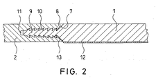
- FIG. 1 The cross-sectional view of a sliding headliner according to FIG the embodiment of the invention can be seen that the loading and / or ventilation strip 2 with a vehicle rear longitudinal front side 7 with the support plate 1, the a vehicle front side longitudinal end face 8, by means of a toothed connection brought together.
- the spline connection consists of a plurality of projections 9, their surfaces 10 fir-tree-like are formed to quickly in complementary trained recesses 11, which are arranged within the loading and / or ventilation strip 2 to lock.
- the support plate with the arranged on its longitudinal end face 8 projections 9 inserted in a simple manner in the recesses 11 and a permanent Connection made between these two parts.
- a towards the vehicle interior to the support plate 1 side arranged heaven fabric 12 is during this mating process with its front end 13 between the longitudinal end faces 7 and 8 and partially clamped in the spline connection, so that for the viewer, the vehicle front end 13 of the fabric heaven 12 in an optically advantageous manner at the junction between the support plate 1 and the bar 2 disappears inside the sliding headliner.
Landscapes
- Engineering & Computer Science (AREA)
- Mechanical Engineering (AREA)
- Vehicle Interior And Exterior Ornaments, Soundproofing, And Insulation (AREA)
- Air-Conditioning For Vehicles (AREA)
Abstract
Description
- Fig. 1
- in einer schematischen Darstellung eine Draufsicht eines Schiebehimmels gemäß einer Ausführungsform der Erfindung, und
- Fig. 2
- eine ausschnittsweise Querschnittsdarstellung des Schiebehimmels gemäß der Ausführungsform der Erfindung.
- 1
- Trägerplatte
- 2
- Be- und/oder Entlüftungsleiste
- 3
- Be- und/oder Entlüftungsschlitze
- 4
- Griffmulde
- 5
- Verbindungsstelle
- 6a, 6b, 6c, 6d
- Führungselemente
- 7
- Längsstirnseite der Leiste 2
- 8
- Längsstirnseite der Trägerplatte 1
- 9
- Vorsprung
- 10
- tannenbaumartige Oberfläche des Vorsprungs
- 11
- Ausnehmung
- 12
- Himmelstoff
- 13
- fahrzeugvorderseitiges Ende des Himmelstoffes
Claims (9)
- Schiebehimmel für ein Schiebedach eines Kraftfahrzeugs mit einer im Wesentlichen starr ausgebildeten Trägerplatte (1) und einer Be- und/oder Entlüftungsleiste (2), deren Längsseiten sich in Fahrzeugquerrichtung erstrecken,
dadurch gekennzeichnet, dass
eine Längsstirnseite (8) eines Endes der Trägerplatte (1) mit einer Längsstirnseite (7) eines Endes der Be- und/oder Entlüftungsleiste (2) verbunden ist. - Schiebehimmel nach Anspruch 1,
dadurch gekennzeichnet, dass
die fahrzeugvorderseitige Längsstirnseite (8) der Trägerplatte (1) mit der fahrzeugrückseitigen Längsstirnseite (7) der Be- und/oder Entlüftungsleiste (2) mittels Verbindungsmittel über ihre gesamten Längen lös- oder unlösbar miteinander verbunden sind. - Schiebehimmel nach Anspruch 2,
dadurch gekennzeichnet, dass
die Verbindungsmittel eine Mehrzahl von an der Längsstirnseite (8) der Trägerplatte (1) angeordnete Vorsprünge (9) ist, deren tannenbaum- oder sägezahnförmig ausgebildete Oberflächen (10) im komplementär dazu ausgebildete Ausnehmungen (11) an der Längsstirnseite (7) der Be- und/oder Entlüftungsleiste (2) eingreifbar sind. - Schiebehimmel nach Anspruch 2,
dadurch gekennzeichnet, dass
die Verbindungsmittel als Klebeverbindung ausgebildet sind. - Schiebehimmel nach Anspruch 4,
dadurch gekennzeichnet, dass
die Klebeverbindung als Nut-Feder-Verbindung und/oder Zapfen-Loch-Verbindung ausgebildet ist. - Schiebehimmel nach einem der Ansprüche 2 - 5,
dadurch gekennzeichnet, dass
die Trägerplatte (1) unterseitig zum Fahrzeuginnenraum hin mit Stoffmaterial (12) bedeckt ist, dessen fahrzeugvorderseitiges Ende (13) zumindest teilweise zwischen den Längsstirnseiten (7, 8) der Trägerplatte (1) und der Be- und/oder Entlüftungsleiste (2) festhaltbar ist. - Schiebehimmel nach einem der vorangegangenen Ansprüche,
dadurch gekennzeichnet, dass
die Trägerplatte (1) und die Be- und/oder Entlüftungsleiste (2) an ihren parallel zur Fahrzeuglängsachse ausgerichteten Seitenkanten Führungselemente (6a, 6b, 6c, 6d) zu deren Gleitlagerung innerhalb von Führungsschienen aufweisen. - Schiebehimmel nach einem der vorangegangenen Ansprüche,
dadurch gekennzeichnet, dass
die Be- und/oder Entlüftungsleiste (2) aus Kunststoff ist und eine darin ausgebildete Griffmulde (4) zum Verschieben des Schiebehimmels mittels einer Handbewegung aufweist. - Schiebehimmel nach Anspruch 8,
dadurch gekennzeichnet, dass
in der Be- und/oder Entlüftungsleiste (2) aus Kunststoff integral ausgebildete Beund/oder Entlüftungsschlitze (3) zum Zu- und/oder Abführen von Luft in den Fahrzeuginnenraum angeordnet sind.
Applications Claiming Priority (2)
| Application Number | Priority Date | Filing Date | Title |
|---|---|---|---|
| DE20312585U | 2003-08-14 | ||
| DE20312585U DE20312585U1 (de) | 2003-08-14 | 2003-08-14 | Schiebehimmel für ein Schiebedach eines Kraftfahrzeugs |
Publications (2)
| Publication Number | Publication Date |
|---|---|
| EP1506887A1 true EP1506887A1 (de) | 2005-02-16 |
| EP1506887B1 EP1506887B1 (de) | 2010-03-03 |
Family
ID=29265743
Family Applications (1)
| Application Number | Title | Priority Date | Filing Date |
|---|---|---|---|
| EP20040019036 Expired - Lifetime EP1506887B1 (de) | 2003-08-14 | 2004-08-11 | Schiebehimmel für ein Schiebedach eines Kraftfahrzeugs |
Country Status (2)
| Country | Link |
|---|---|
| EP (1) | EP1506887B1 (de) |
| DE (2) | DE20312585U1 (de) |
Cited By (1)
| Publication number | Priority date | Publication date | Assignee | Title |
|---|---|---|---|---|
| WO2013076019A1 (de) * | 2011-11-22 | 2013-05-30 | Webasto SE | Schiebehimmel, dachanordnung mit solch einem schiebehimmel und verfahren zum herstellen solch eines schiebehimmels |
Families Citing this family (1)
| Publication number | Priority date | Publication date | Assignee | Title |
|---|---|---|---|---|
| DE102016111220B4 (de) * | 2016-06-20 | 2023-09-21 | Lisa Dräxlmaier GmbH | Verfahren zum Herstellen eines Innenausstattungsteils |
Citations (6)
| Publication number | Priority date | Publication date | Assignee | Title |
|---|---|---|---|---|
| US4717200A (en) * | 1985-08-02 | 1988-01-05 | Krueger Peter | Sliding liner for a sliding roof for automobiles |
| DE3930054A1 (de) * | 1989-09-08 | 1991-03-21 | Webasto Ag Fahrzeugtechnik | Luefterdach fuer fahrzeuge |
| DE19534288C1 (de) * | 1995-09-15 | 1996-10-31 | Webasto Karosseriesysteme | Rollovorrichtung für Fahrzeugdächer |
| EP0940279A2 (de) * | 1998-03-02 | 1999-09-08 | Ruthard Dipl.-Ing. Marowsky | Sonnenschutz für ein Schiebedach eines Kraftfahrzeugs und Innenhimmel eines Kraftfahrzeugs |
| US6386626B1 (en) * | 1999-11-18 | 2002-05-14 | Aisin Seiki Kabushiki Kaisha | Sunshade for vehicle sunroof |
| EP1393943A1 (de) * | 2002-09-02 | 2004-03-03 | ArvinMeritor GmbH | Schiebehimmel für ein Kfz-Schiebe- oder Kfz-Schiebehebedach |
-
2003
- 2003-08-14 DE DE20312585U patent/DE20312585U1/de not_active Expired - Lifetime
-
2004
- 2004-08-11 DE DE200450010838 patent/DE502004010838D1/de not_active Expired - Lifetime
- 2004-08-11 EP EP20040019036 patent/EP1506887B1/de not_active Expired - Lifetime
Patent Citations (6)
| Publication number | Priority date | Publication date | Assignee | Title |
|---|---|---|---|---|
| US4717200A (en) * | 1985-08-02 | 1988-01-05 | Krueger Peter | Sliding liner for a sliding roof for automobiles |
| DE3930054A1 (de) * | 1989-09-08 | 1991-03-21 | Webasto Ag Fahrzeugtechnik | Luefterdach fuer fahrzeuge |
| DE19534288C1 (de) * | 1995-09-15 | 1996-10-31 | Webasto Karosseriesysteme | Rollovorrichtung für Fahrzeugdächer |
| EP0940279A2 (de) * | 1998-03-02 | 1999-09-08 | Ruthard Dipl.-Ing. Marowsky | Sonnenschutz für ein Schiebedach eines Kraftfahrzeugs und Innenhimmel eines Kraftfahrzeugs |
| US6386626B1 (en) * | 1999-11-18 | 2002-05-14 | Aisin Seiki Kabushiki Kaisha | Sunshade for vehicle sunroof |
| EP1393943A1 (de) * | 2002-09-02 | 2004-03-03 | ArvinMeritor GmbH | Schiebehimmel für ein Kfz-Schiebe- oder Kfz-Schiebehebedach |
Cited By (1)
| Publication number | Priority date | Publication date | Assignee | Title |
|---|---|---|---|---|
| WO2013076019A1 (de) * | 2011-11-22 | 2013-05-30 | Webasto SE | Schiebehimmel, dachanordnung mit solch einem schiebehimmel und verfahren zum herstellen solch eines schiebehimmels |
Also Published As
| Publication number | Publication date |
|---|---|
| EP1506887B1 (de) | 2010-03-03 |
| DE20312585U1 (de) | 2003-10-16 |
| DE502004010838D1 (de) | 2010-04-15 |
Similar Documents
| Publication | Publication Date | Title |
|---|---|---|
| DE69605905T2 (de) | Befestigungsanordnung für eine hintere abdeckplatte eines fahrzeugs | |
| DE102016007854B4 (de) | Aufnahmevorrichtung mit Rollo | |
| EP2011723B1 (de) | Luftleiteinrichtung eines Kraftfahrzeuges | |
| DE19519779A1 (de) | Rahmenseitenteil einer Karosserie von Kraftfahrzeugen, insbesondere Personenkraftwagen, und Verfahren zu dessen Herstellung | |
| DE602005002868T2 (de) | Kraftfahrzeugrahmenanordnung | |
| DE102016009136B4 (de) | Kraftwagen mit einem Dachmodul | |
| EP1522442B1 (de) | Fahrzeugfestes Führungssytem und Verfahren zum Herstellen eines fahrzeugfesten Führungssystems | |
| EP2134915B1 (de) | Führungsschienenanordnung und mitnehmer für kraftfahrzeug-fensterheber sowie verfahren zu deren herstellung | |
| DE3727719A1 (de) | Rahmenanordnung fuer ein fahrzeugdach | |
| DE60011522T2 (de) | Konstruktion eines öffnungsfähigen Fahrzeugdaches | |
| DE102007058268A1 (de) | Fahrzeugtür | |
| DE19911450B4 (de) | Konstruktion zur Installierung eines Armaturenbretts | |
| DE102009042415A1 (de) | Personenkraftwagen | |
| DE69303106T2 (de) | Windableiter für Scheibenwischvorrichtung mit abnehmbarer weicher Kante | |
| DE10122637B4 (de) | Dichtungsanordnung für eine Kraftfahrzeugtüre und/oder ein Kraftfahrzeugfenster | |
| DE102004017569B4 (de) | Fahrzeugbauteil mit einer Führungsschienenstruktur | |
| EP1506887B1 (de) | Schiebehimmel für ein Schiebedach eines Kraftfahrzeugs | |
| DE102008062501A1 (de) | Energieabsorptionsvorrichtung | |
| DE102021102763A1 (de) | Trennstrebe für ein kraftfahrzeug und verfahren zum herstellen einer trennstrebe | |
| DE102007008821A1 (de) | Fahrzeugdach | |
| EP0314119A1 (de) | Bordwandprofil mit daran angeordneter Zurrschiene und damit hergestellte Bordwand | |
| EP1721770A2 (de) | Führungsschiene für ein Kfz-Schiebedachsystem | |
| DE19732700B4 (de) | Rahmenanordnung für ein Deckelteil eines Fahrzeugdaches | |
| DE10106738A1 (de) | Vorrichtung zum Festlegen einer Heckscheibe an einem Bezug eines Cabrioletverdecks | |
| EP3319827B1 (de) | Dachmodul für einen kraftwagen |
Legal Events
| Date | Code | Title | Description |
|---|---|---|---|
| PUAI | Public reference made under article 153(3) epc to a published international application that has entered the european phase |
Free format text: ORIGINAL CODE: 0009012 |
|
| AK | Designated contracting states |
Kind code of ref document: A1 Designated state(s): AT BE BG CH CY CZ DE DK EE ES FI FR GB GR HU IE IT LI LU MC NL PL PT RO SE SI SK TR |
|
| AX | Request for extension of the european patent |
Extension state: AL HR LT LV MK |
|
| 17P | Request for examination filed |
Effective date: 20050317 |
|
| 17Q | First examination report despatched |
Effective date: 20050627 |
|
| AKX | Designation fees paid |
Designated state(s): DE FR GB NL |
|
| GRAP | Despatch of communication of intention to grant a patent |
Free format text: ORIGINAL CODE: EPIDOSNIGR1 |
|
| GRAS | Grant fee paid |
Free format text: ORIGINAL CODE: EPIDOSNIGR3 |
|
| GRAA | (expected) grant |
Free format text: ORIGINAL CODE: 0009210 |
|
| AK | Designated contracting states |
Kind code of ref document: B1 Designated state(s): DE FR GB NL |
|
| REG | Reference to a national code |
Ref country code: GB Ref legal event code: FG4D Free format text: NOT ENGLISH |
|
| REF | Corresponds to: |
Ref document number: 502004010838 Country of ref document: DE Date of ref document: 20100415 Kind code of ref document: P |
|
| REG | Reference to a national code |
Ref country code: NL Ref legal event code: VDEP Effective date: 20100303 |
|
| PG25 | Lapsed in a contracting state [announced via postgrant information from national office to epo] |
Ref country code: NL Free format text: LAPSE BECAUSE OF FAILURE TO SUBMIT A TRANSLATION OF THE DESCRIPTION OR TO PAY THE FEE WITHIN THE PRESCRIBED TIME-LIMIT Effective date: 20100303 |
|
| PLBE | No opposition filed within time limit |
Free format text: ORIGINAL CODE: 0009261 |
|
| STAA | Information on the status of an ep patent application or granted ep patent |
Free format text: STATUS: NO OPPOSITION FILED WITHIN TIME LIMIT |
|
| 26N | No opposition filed |
Effective date: 20101206 |
|
| PGFP | Annual fee paid to national office [announced via postgrant information from national office to epo] |
Ref country code: DE Payment date: 20140821 Year of fee payment: 11 |
|
| PGFP | Annual fee paid to national office [announced via postgrant information from national office to epo] |
Ref country code: FR Payment date: 20140819 Year of fee payment: 11 Ref country code: GB Payment date: 20140821 Year of fee payment: 11 |
|
| REG | Reference to a national code |
Ref country code: DE Ref legal event code: R119 Ref document number: 502004010838 Country of ref document: DE |
|
| GBPC | Gb: european patent ceased through non-payment of renewal fee |
Effective date: 20150811 |
|
| REG | Reference to a national code |
Ref country code: FR Ref legal event code: ST Effective date: 20160429 |
|
| PG25 | Lapsed in a contracting state [announced via postgrant information from national office to epo] |
Ref country code: DE Free format text: LAPSE BECAUSE OF NON-PAYMENT OF DUE FEES Effective date: 20160301 Ref country code: GB Free format text: LAPSE BECAUSE OF NON-PAYMENT OF DUE FEES Effective date: 20150811 |
|
| PG25 | Lapsed in a contracting state [announced via postgrant information from national office to epo] |
Ref country code: FR Free format text: LAPSE BECAUSE OF NON-PAYMENT OF DUE FEES Effective date: 20150831 |