EP1505825B1 - Video display system and video display control apparatus - Google Patents
Video display system and video display control apparatus Download PDFInfo
- Publication number
- EP1505825B1 EP1505825B1 EP03721089.5A EP03721089A EP1505825B1 EP 1505825 B1 EP1505825 B1 EP 1505825B1 EP 03721089 A EP03721089 A EP 03721089A EP 1505825 B1 EP1505825 B1 EP 1505825B1
- Authority
- EP
- European Patent Office
- Prior art keywords
- screen
- display unit
- display
- base station
- operation instruction
- Prior art date
- Legal status (The legal status is an assumption and is not a legal conclusion. Google has not performed a legal analysis and makes no representation as to the accuracy of the status listed.)
- Expired - Lifetime
Links
Images


Classifications
-
- G—PHYSICS
- G06—COMPUTING; CALCULATING OR COUNTING
- G06F—ELECTRIC DIGITAL DATA PROCESSING
- G06F3/00—Input arrangements for transferring data to be processed into a form capable of being handled by the computer; Output arrangements for transferring data from processing unit to output unit, e.g. interface arrangements
- G06F3/01—Input arrangements or combined input and output arrangements for interaction between user and computer
- G06F3/048—Interaction techniques based on graphical user interfaces [GUI]
- G06F3/0487—Interaction techniques based on graphical user interfaces [GUI] using specific features provided by the input device, e.g. functions controlled by the rotation of a mouse with dual sensing arrangements, or of the nature of the input device, e.g. tap gestures based on pressure sensed by a digitiser
- G06F3/0488—Interaction techniques based on graphical user interfaces [GUI] using specific features provided by the input device, e.g. functions controlled by the rotation of a mouse with dual sensing arrangements, or of the nature of the input device, e.g. tap gestures based on pressure sensed by a digitiser using a touch-screen or digitiser, e.g. input of commands through traced gestures
- G06F3/04883—Interaction techniques based on graphical user interfaces [GUI] using specific features provided by the input device, e.g. functions controlled by the rotation of a mouse with dual sensing arrangements, or of the nature of the input device, e.g. tap gestures based on pressure sensed by a digitiser using a touch-screen or digitiser, e.g. input of commands through traced gestures for inputting data by handwriting, e.g. gesture or text
-
- H—ELECTRICITY
- H04—ELECTRIC COMMUNICATION TECHNIQUE
- H04N—PICTORIAL COMMUNICATION, e.g. TELEVISION
- H04N21/00—Selective content distribution, e.g. interactive television or video on demand [VOD]
- H04N21/40—Client devices specifically adapted for the reception of or interaction with content, e.g. set-top-box [STB]; Operations thereof
- H04N21/41—Structure of client; Structure of client peripherals
- H04N21/4104—Peripherals receiving signals from specially adapted client devices
- H04N21/4126—The peripheral being portable, e.g. PDAs or mobile phones
- H04N21/41265—The peripheral being portable, e.g. PDAs or mobile phones having a remote control device for bidirectional communication between the remote control device and client device
-
- H—ELECTRICITY
- H04—ELECTRIC COMMUNICATION TECHNIQUE
- H04N—PICTORIAL COMMUNICATION, e.g. TELEVISION
- H04N21/00—Selective content distribution, e.g. interactive television or video on demand [VOD]
- H04N21/40—Client devices specifically adapted for the reception of or interaction with content, e.g. set-top-box [STB]; Operations thereof
- H04N21/41—Structure of client; Structure of client peripherals
- H04N21/422—Input-only peripherals, i.e. input devices connected to specially adapted client devices, e.g. global positioning system [GPS]
- H04N21/42204—User interfaces specially adapted for controlling a client device through a remote control device; Remote control devices therefor
- H04N21/42206—User interfaces specially adapted for controlling a client device through a remote control device; Remote control devices therefor characterized by hardware details
- H04N21/42208—Display device provided on the remote control
-
- H—ELECTRICITY
- H04—ELECTRIC COMMUNICATION TECHNIQUE
- H04N—PICTORIAL COMMUNICATION, e.g. TELEVISION
- H04N21/00—Selective content distribution, e.g. interactive television or video on demand [VOD]
- H04N21/40—Client devices specifically adapted for the reception of or interaction with content, e.g. set-top-box [STB]; Operations thereof
- H04N21/41—Structure of client; Structure of client peripherals
- H04N21/422—Input-only peripherals, i.e. input devices connected to specially adapted client devices, e.g. global positioning system [GPS]
- H04N21/42204—User interfaces specially adapted for controlling a client device through a remote control device; Remote control devices therefor
- H04N21/42206—User interfaces specially adapted for controlling a client device through a remote control device; Remote control devices therefor characterized by hardware details
- H04N21/42224—Touch pad or touch panel provided on the remote control
-
- H—ELECTRICITY
- H04—ELECTRIC COMMUNICATION TECHNIQUE
- H04N—PICTORIAL COMMUNICATION, e.g. TELEVISION
- H04N21/00—Selective content distribution, e.g. interactive television or video on demand [VOD]
- H04N21/40—Client devices specifically adapted for the reception of or interaction with content, e.g. set-top-box [STB]; Operations thereof
- H04N21/41—Structure of client; Structure of client peripherals
- H04N21/426—Internal components of the client ; Characteristics thereof
- H04N21/42607—Internal components of the client ; Characteristics thereof for processing the incoming bitstream
- H04N21/4263—Internal components of the client ; Characteristics thereof for processing the incoming bitstream involving specific tuning arrangements, e.g. two tuners
-
- H—ELECTRICITY
- H04—ELECTRIC COMMUNICATION TECHNIQUE
- H04N—PICTORIAL COMMUNICATION, e.g. TELEVISION
- H04N21/00—Selective content distribution, e.g. interactive television or video on demand [VOD]
- H04N21/40—Client devices specifically adapted for the reception of or interaction with content, e.g. set-top-box [STB]; Operations thereof
- H04N21/43—Processing of content or additional data, e.g. demultiplexing additional data from a digital video stream; Elementary client operations, e.g. monitoring of home network or synchronising decoder's clock; Client middleware
- H04N21/438—Interfacing the downstream path of the transmission network originating from a server, e.g. retrieving MPEG packets from an IP network
- H04N21/4383—Accessing a communication channel
-
- H—ELECTRICITY
- H04—ELECTRIC COMMUNICATION TECHNIQUE
- H04N—PICTORIAL COMMUNICATION, e.g. TELEVISION
- H04N21/00—Selective content distribution, e.g. interactive television or video on demand [VOD]
- H04N21/40—Client devices specifically adapted for the reception of or interaction with content, e.g. set-top-box [STB]; Operations thereof
- H04N21/43—Processing of content or additional data, e.g. demultiplexing additional data from a digital video stream; Elementary client operations, e.g. monitoring of home network or synchronising decoder's clock; Client middleware
- H04N21/442—Monitoring of processes or resources, e.g. detecting the failure of a recording device, monitoring the downstream bandwidth, the number of times a movie has been viewed, the storage space available from the internal hard disk
- H04N21/44213—Monitoring of end-user related data
-
- H—ELECTRICITY
- H04—ELECTRIC COMMUNICATION TECHNIQUE
- H04N—PICTORIAL COMMUNICATION, e.g. TELEVISION
- H04N5/00—Details of television systems
- H04N5/44—Receiver circuitry for the reception of television signals according to analogue transmission standards
-
- H—ELECTRICITY
- H04—ELECTRIC COMMUNICATION TECHNIQUE
- H04N—PICTORIAL COMMUNICATION, e.g. TELEVISION
- H04N5/00—Details of television systems
- H04N5/44—Receiver circuitry for the reception of television signals according to analogue transmission standards
- H04N5/50—Tuning indicators; Automatic tuning control
-
- H—ELECTRICITY
- H04—ELECTRIC COMMUNICATION TECHNIQUE
- H04N—PICTORIAL COMMUNICATION, e.g. TELEVISION
- H04N5/00—Details of television systems
- H04N5/38—Transmitter circuitry for the transmission of television signals according to analogue transmission standards
Landscapes
- Engineering & Computer Science (AREA)
- Multimedia (AREA)
- Signal Processing (AREA)
- Human Computer Interaction (AREA)
- Theoretical Computer Science (AREA)
- General Engineering & Computer Science (AREA)
- Health & Medical Sciences (AREA)
- General Physics & Mathematics (AREA)
- Physics & Mathematics (AREA)
- General Health & Medical Sciences (AREA)
- Social Psychology (AREA)
- Computer Networks & Wireless Communication (AREA)
- Databases & Information Systems (AREA)
- Two-Way Televisions, Distribution Of Moving Picture Or The Like (AREA)
- User Interface Of Digital Computer (AREA)
- Controls And Circuits For Display Device (AREA)
- Details Of Television Systems (AREA)
- Selective Calling Equipment (AREA)
- Television Systems (AREA)
Description
- The present invention relates to a video display system including at least two display units and a base station that supplies a video signal to the display units, and a video display controller for use in the video display system.
- This application claims the priority of the Japanese Patent Application No.
2002-137774 - In a TV set with an accessory remote commander (will be referred to as "remote controller" hereunder), if any, the user of the TV set can make an image quality control, timer setting or the like, for example, by using the remote controller to display a performable-operations menu on a display screen of the TV set, and select an item for an intended operation, image quality control or timer setting, from the menu being displayed on the display screen, and can make an image quality control or timer setting by operating the remote controller according to a guidance or the like being displayed on the display screen.
- Also, in a receiver that receives a satellite broadcast signal, such as STB (set-top box), IRD (integrated receiver decoder) or the like, data such as a so-called electronic program guide (EPG) is displayed on the display screen of a monitor receiver. In this case, selection, by a remote controller accessory to the receiver, of a desired program according to an EPG being displayed on the display screen of the monitor receiver leads to selection of a desired one of channels available on the receiver.
- As above, in a TV set or a receiver that receives a television broadcast signal, a combination of the display of instructive information such as a menu, guidance or EPG on the display screen with a user's operation of the remote controller enables a user-friendly, relatively easy selection of a desired operation.
- In some cases, however, the use of the remote controller will be made complicated by the above-mentioned combination of the display, on the display screen of the TV set or the like, of necessary information such as a menu, guidance or the like for having the TV set, STB or IRD make a user-intended operation in response to a remote-control operation made by the user in watching the instructive information being displayed on the screen.
- For instance, the user has to scroll through a plurality of menu pages, if any, in order to select a menu page including a desired item of operation, the user has to operate the remote controller many times to move the cursor on the display screen, and also the user has to operate the remote controller to "set" each selected item of operation.
- Employment of an LCD (liquid crystal display) panel or the like has given birth to more compact and lightweight monitors such as TV sets. Thus, the user can transport such a modern TV set easily and use it near him or her. In case the user uses such a TV set near him, he will not need any more remote controller for operating his TV set. Rather, the user will be bored with the operation of a remote controller as an external input unit for a receiver or the like, that supplies video and audio signals to the TV set.
- On this account, the Applicant of the present invention proposed, in the Japanese Published Unexamined Patent Application No.
2002-34023 - With the two-way communication system disclosed in the above Applicant's Japanese Published Unexamined Patent Publication No.
2002-34023 -
EP 1189391 discloses a command processing method for a radio LAN system composed of a plurality of terminals and at least one base apparatus. The method prevents users of the terminals from suffering from confusion or conflict between the users with regard to handling of a command issued from any of the terminals and from misunderstanding that the system has failed.US6097441 also discloses methods for using cooperating but physically independent displays for enhanced viewing of data streams. - The invention is defined in the appended claims.
- Accordingly, the present invention has an object to overcome the above-mentioned drawbacks of the related art by providing a video display system permitting the user, who is going to supply a video signal from a base station to a plurality of display units by the aforementioned two-way communication system already proposed by the Applicant of the present invention, to transfer a video signal between the base station and plurality of display units by stroking the surface of a display screen of the display unit with the finger, and thus the user to intuitively select an operation in a manner quite different from that in which he or she will make such a selection using buttons provided on the conventional remote controller, and a video display controller for the video display system.
- The above object can be attained by providing a video display system including a minimum of two display units and a base station that supplies a video signal to the display units, in which according to the present invention, the base station includes: a minimum of two tuning means capable of selecting a reception channel independently of each other; a video signal output means for supplying a video signal on a reception channel selected by each of the minimum of two tuning means to the minimum of two display units; a two-way communication means for transferring information signals to and from at least one of the minimum of two display units; and a control means for controlling the minimum of two tuning means, and at least one of the minimum of two display units which transfers information signals to and from the base station includes:
- a two-way communication means for transferring the information signals to and from the base station; a video display for displaying an image corresponding to the video signal supplied from the base station; a screen-touch positioning means provided on a display screen of the video display and which the user is to touch and stroke to recognize the location of a user's touch on the surface of the display screen; and an operation instruction generating means for generating a display-image select instruction corresponding to the direction of a user's finger stroke on the basis of a detection output of screen-touch location from the screen-touch positioning means, receiving the display-image select instruction generated by the operation instruction generating means via the two-way communication means, the controlling means in the base station controlling the channel selecting operation of the minimum of two tuning means according to the display-image select instruction.
- In the above video display system according to the present invention, the screen-touch positioning means includes a touch panel and a coordinate detector that recognizes the location of the user's touch on the display screen as a coordinate position, for example, extracts sample points at every fixed times or distances from a detection output given by the coordinate detector correspondingly to a user's stroking of the touch panel, judges, based on an aspect ratio of the user's stroking, in which direction the stroking has been made, horizontal or vertical, and has the operation instruction generating means generate a display-image select instruction corresponding to the result of the judgment.
- Also, in the above video display system according to the present invention, the operation instruction generating means generates a display-image select instruction corresponding to the direction of a user's stroking taken as a valid one when the stroke is larger in length than specified and shorter in duration than specified, for example.
- Also in the above video display system according to the present invention, the display unit including the two-way communication means that transfers information signals to and from the base station has the operation instruction generating means generate an operation instruction formed with a channel select command assigned to a horizontal stroke, for example, to thereby control the channel selecting operation of the tuning means that supplies a video signal from the base station to the display unit.
- Also in the above video display system according to the present invention, the display unit including the two-way communication means that transfers information signals to and from the base station has the operation instruction generating means generate, in case the user strokes the display screen with the finger upward, downward or downward and upward, for example, an operation instruction formed with any of first to third screen swap commands assigned to the finger stroke, as a display-image select instruction corresponding to the stroking direction, to thereby control the channel selection for setting, according to an operation instruction formed with the first screen swap command assigned to the finger stroke, the reception channel of the tuning means that supplies a video signal from the base station to the display unit to that of the tuning means that supplies from the base station to the other display unit; control the channel selection for setting, according to an operation instruction formed with the second screen swap command assigned to the finger stroke, the reception channel of the tuning means that supplies a video signal from the base station to the other display unit to that of the tuning means that supplies from the base station to the display unit; and control the channel selection for swapping, according to the operation instruction formed with the third screen swap command assigned to the finger stroke, the reception channel of the tuning means that supplies a video signal from the base station to the display unit with that of the tuning means that supplies from the base station to the other display unit.
- Also in the above video display system according to the present invention, the display unit including the two-way communication means that transfers information signals to and from the base station provides an animation display indicating that a screen swapping has been made correspondingly to the first to third screen swap commands, for example.
- Also in the above video display system according to the present invention, the display unit including the two-way communication means that transfers information signals to and from the base station has the operation instruction generating means generate an operation instruction formed with a channel select command assigned to a horizontal stroke on the basis of a detection output of screen-touch location from the screen-touch positioning means, for example, and transmits the operation instruction to the base station via the two-way communication means, to thereby control the channel selecting operation of the tuning means that supplies a video signal from the base station to the display unit.
- Also in the above video display system according to the present invention, the display unit including the two-way communication means that transfers information signals to and from the base station has the operation instruction generating means generate an operation instruction formed with a screen swap command assigned to a vertical stroke on the basis of a detection output of screen-touch location from the screen-touch positioning means, for example, and transmits the operation instruction to the base station via the two-way communication means, to thereby control the channel selection for setting the reception channel of the tuning means that supplies the video signal to the display unit to that of the tuning means that supplies the video signal from the base station to the other display unit.
- Also in the above video display system according to the present invention, the display unit including the two-way communication means that transfers information signals to and from the base station judges whether a screen swapping corresponding to the vertical stroke is possible and generates an operation instruction formed with the screen swap command assigned to the finger stroke when the screen swap operation is possible, for example, to thereby call an operation for selection of the reception channel of the other display unit and provide an animation display indicating that a screen swapping corresponding to the vertical stroke has been made.
- Also in the above video display system according to the present invention, receiving a call for an operation for selection of a reception channel selection under the screen swap command, for example, the other display unit controls screen fade-out and sound muting and makes a signal selection to fade in the screen and cancel the sound muting.
- Also in the above video display system according to the present invention, the display unit including the two-way communication means that transfers information signals to and from the base station has the operation instruction generating means generate an operation instruction formed with a screen-swap command assigned to a vertical stroke on the basis of a detection output of screen-touch location from the screen-touch positioning means, for example, and transmits the operation instruction to the base station via the two-way communication means, to thereby control the channel selection for setting the reception channel of the tuning means that supplies the video signal from the base station to the other display unit to that of the tuning means that supplies the video signal from the base station to the display unit.
- Also in the above video display system according to the present invention, the display unit including the two-way communication means that transfers information signals to and from the base station judges whether the screen swapping corresponding to the vertical stroke is possible, for example, catches the reception channel of the other display unit when the screen swapping is determined to be possible, generates an operation instruction formed with the screen swap command assigned to the finger stroke, calls an operation for selection of the reception channel of the other display unit, and provides an animation display indicating that the screen swapping corresponding to the vertical stroke has been done, to thereby make a channel selection for switching the reception channel of the display unit to the caught reception channel of the other display unit.
- Also in the above video display system according to the present invention, receiving a call for an operation for selection of a reception channel under the screen swap command, for example, the other display unit makes a catch indication to inform that its reception channel has been caught by the display unit with no channel selection.
- Also in the above video display system according to the present invention, the display unit including the two-way communication means that transfers information signals to and from the base station has the operation instruction generating means generate an operation instruction formed with a screen swap command assigned to a vertical stroke on the basis of a detection output of screen-touch location from the screen-touch positioning means, for example, and transmits the operation instruction to the base station via the two-way communication means, to thereby control the channel selection for swapping the reception channel of the tuning means that supplies a video signal from the base station to the display unit with that of the tuning means that supplies a video signal from the base station to the other display unit.
- Also in the above video display system according to the present invention, the display unit including the two-way communication means that transfers information signals to and from the base station judges whether a screen swapping corresponding to the vertical stroke is possible, for example, catches the reception channel of the other display unit when the screen swapping is determined to be possible, generates an operation instruction formed with a screen swap command assigned to the finger stroke, calls an operation for switching the reception channel of the other display unit to that of the display unit, and provides an animation display indicating that the screen swapping corresponding to the vertical stroke has been done, to thereby make a channel selection for switching the reception channel of the display unit to the caught reception channel of the other display unit.
- Also in the above video display system according to the present invention, receiving a call for an operation for selection of a reception channel under the screen swap command, for example, the other display unit controls screen fade-out and sound muting and makes a signal selection to fade in the screen and cancel the sound muting.
- Also, the above object can be attained by providing a video display system including a minimum of two display units and a base station that supplies a video signal to the display units, in which according to the present invention: the base station includes: a signal selecting means for selecting one of a plurality of input video signals for supply to the minimum of two display units; a video signal output means for supplying the video signal selected by the signal selecting means to the minimum of two display units; a two-way communication means for transferring information signals to and from at least one of the minimum of two display units; and a control means for controlling the signal selecting means, and at least one of the minimum of two display units which transfers information signals to and from the base station includes: a two-way communication means for transferring the information signals to and from the base station; a video display for displaying an image corresponding to the video signal supplied from the base station; a screen-touch positioning means provided on a display screen of the video display and which the user is to touch and stroke to recognize the location of a user's touch on the surface of the display screen; and an operation instruction generating means for generating a display-image select instruction corresponding to the direction of a user's finger stroke on the basis of a detection output of screen-touch location from the screen-touch positioning means, receiving the display-image select instruction generated by the operation instruction generating means via the two-way communication means, the controlling means in the base station controlling the signal selecting operation of the signal selecting means according to the display-image select instruction.
- In the above video display system according to the present invention, the screen-touch positioning means includes a touch panel and a coordinate detector that recognizes the location of the user's touch on the display screen as a coordinate position, for example, extracts sample points at every fixed times or distances from a detection output given by the coordinate detector correspondingly to a user's stroking of the touch panel, judges, based on an aspect ratio of the stroke, in which direction the stroke has been made, horizontal or vertical, and has the operation instruction generating means generate a display-image select instruction corresponding to the result of the judgment.
- Also, in the above video display system according to the present invention, the operation instruction generating means generates a display-image select instruction corresponding to the direction of a user's finger stroke taken as a valid one when the stroke is larger in length than specified and shorter in duration than specified, for example.
- Also in the above video display system according to the present invention, the display unit including the two-way communication means that transfers information signals to and from the base station has the operation instruction generating means generate an operation instruction formed with a display-image select command assigned to a horizontal stroke, for example, to thereby control the signal selecting operation of the signal selecting means that supplies a video signal from the base station to the display unit.
- Also in the above video display system according to the present invention, the display unit including the two-way communication means that transfers information signals to and from the base station has the operation instruction generating means generate, in case the user strokes the display screen with the finger upward, downward or downward and upward, for example, an operation instruction formed with any of first to third screen swap commands assigned to the finger stroke, as a display-image select instruction corresponding to the stroking direction, to thereby control the signal selecting means to supply the video signal supplied from the base station to the display unit to the other display unit as well according to the operation instruction formed with the first screen swap command assigned to the finger stroke; control the signal selecting means to supply the video signal supplied from the base station to the other display unit to the display unit as well according to the operation instruction formed with the second screen swap command assigned to the finger stroke; and control the signal selecting means to supply the other display unit with the video signal supplied from the base station to the display unit while supplying the display unit with the video signal supplied from the base station to the other display unit, according to the operation instruction formed with the third screen swap command assigned to the finger stroke.
- Also in the above video display system according to the present invention, the display unit including the two-way communication means that transfers information signals to and from the base station provides an animation display indicating that a screen swapping corresponding to the first to third screen swap commands has been made, for example.
- Also in the above video display system according to the present invention, the display unit including the two-way communication means that transfers information signals to and from the base station has the operation instruction generating means generate an operation instruction formed with a screen swap command assigned to a vertical stroke on the basis of a detection output of screen-touch location from the screen-touch positioning means, for example, and transmits the operation instruction to the base station via the two-way communication means, to thereby control the signal selecting means to supply the video signal supplied from the base station to the display unit to the other display unit as well.
- Also in the above video display system according to the present invention, the display unit including the two-way communication means that transfers information signals to and from the base station judges whether a screen swapping corresponding to the vertical stroke is possible and generates an operation instruction formed with the screen swap command assigned to the finger stroke when the screen swap operation is possible, for example, to thereby call an operation for selecting a video signal at the other display unit and provide an animation display indicating that a screen swapping corresponding to the vertical stroke has been made.
- Also in the above video display system according to the present invention, receiving a call for an operation for selection of a video signal under the screen swap command, for example, the other display unit controls screen fade-out and sound muting and makes a signal selection to fade in the screen and cancel the sound muting.
- Also in the above video display system according to the present invention, the display unit including the two-way communication means that transfers information signals to and from the base station has the operation instruction generating means generate an operation instruction formed with a screen swap command assigned to a vertical stroke on the basis of a detection output of screen-touch location from the screen-touch positioning means, for example, and transmits the operation instruction to the base station via the two-way communication means, to thereby control the signal selecting means to supply the video signal supplied from the base station to the other display unit to the display unit as well.
- Also in the above video display system according to the present invention, the display unit including the two-way communication means that transfers information signals to and from the base station judges whether the screen swapping corresponding to the vertical stroke is possible, catches input information to the other display unit when the screen swapping is determined to be possible, generates an operation instruction formed with the screen swap command assigned to the finger stroke, calls an operation for selection of the video signal at the other display unit, and provides an animation display indicating that a screen swapping corresponding to the vertical stroke has been done, for example, to thereby make a signal selection for switching the video signal at the display unit to that formed from the caught input information to the other display unit.
- Also in the above video display system according to the present invention, receiving a call for an operation for selection of a video signal under the screen swap command, for example, the other display unit makes a catch indication to inform that the input information has been caught by the display unit with no video signal selection.
- Also in the above video display system according to the present invention, the display unit including the two-way communication means that transfers information signals to and from the base station has the operation instruction generating means generate an operation instruction formed with a screen swap command assigned to a vertical stroke on the basis of a detection output of screen-touch location from the screen-touch positioning means, for example, and transmits the operation instruction to the base station via the two-way communication means, to thereby control the signal selecting means to supply the other display unit with the video signal supplied from the base station to the display unit while supplying the display unit with the video signal supplied from the based station to the other display unit.
- Also in the above video display system according to the present invention, the display unit including the two-way communication means that transfers information signals to and from the base station judges whether the screen swapping corresponding to the vertical stroke is possible, catches input information to the other display unit when the screen swapping is determined to be possible, generates an operation instruction formed with the screen swap command assigned to the vertical stroke, calls an operation for switching the video signal at the other display unit to that at the display unit, and provides an animation display indicating that a screen swapping corresponding to the vertical stroke has been done, for example, to thereby make a signal selection for switching the video signal at the display unit to that formed from the caught input information to the other display unit.
- Also in the above video display system according to the present invention, receiving a call for an operation for selection of a video signal under the screen swap command, for example, the other display unit controls screen fade-out and sound muting and makes a signal selection to fade in the screen and cancel the sound muting.
- Also, the above object can be attained by providing a video display controller for use in a video display system including a minimum of two display units and a base station that supplies a video signal to the display units, in which according to the present invention: the base station includes: a minimum of two tuning means each capable of selecting a reception channel independently of each other; a video signal output means for supplying a video signal on the reception channel selected by each of the minimum of two tuning means to the minimum of two display units; a two-way communication means for transferring information signals to and from at least one of the minimum of two display units; and a control means for controlling the minimum of two tuning means, and at least one of the minimum of two display units which transfers information signals to and from the base station includes: a two-way communication means for transferring the information signals to and from the base station; a video display for displaying an image corresponding to the video signal supplied from the base station; a screen-touch positioning means provided on a display screen of the video display and which the user is to touch and stroke to recognize the location of a user's touch on the surface of the display screen; and an operation instruction generating means for generating a display-image select instruction corresponding to the direction of a user's finger stroke on the basis of a detection output of screen-touch location from the screen-touch positioning means, receiving the display-image select instruction generated by the operation instruction generating means in the display unit via the two-way communication means, the controlling means in the base station controlling the channel selecting operation of the minimum of two tuning means according to the display-image select instruction.
- In the above video display controller according to the present invention, the screen-touch positioning means includes a touch panel and a coordinate detector that recognizes the location of the user's touch on the display screen as a coordinate position, for example, extracts sample points at every fixed times or distances from a detection output given by the coordinate detector correspondingly to a user's stroking of the touch panel, judges, based on an aspect ratio of the stroke, in which direction the stroke has been made, horizontal or vertical, and has the operation instruction generating means generate a display-image select instruction corresponding to the result of the judgment.
- Also, in the above video display controller according to the present invention, the operation instruction generating means generates a display-image select instruction corresponding to the direction of a user's finger stroke taken as a valid one when the stroke is larger in length than specified and shorter in duration than specified, for example.
- Also in the above video display controller according to the present invention, the display unit including the two-way communication means that transfers information signals to and from the base has the operation instruction generating means generate an operation instruction formed with a channel select command assigned to a horizontal stroke, for example, to thereby control the channel selecting operation of the tuning means that supplies a video signal from the base station to the display unit
- Also in the above video display controller according to the present invention, the display unit including the two-way communication means that transfers information signals to and from the base station has the operation instruction generating means generate, in case the user strokes the display screen with the finger upward, downward or downward and upward, for example, an operation instruction formed with any of first to third screen swap commands assigned to the finger stroke, as a display-image select instruction corresponding to the stroking direction, to thereby control the channel selection for setting, according to the operation instruction formed with the first screen swap command assigned to the finger stroke, the reception channel of the tuning means that supplies a video signal from the base station to the display unit to that of the tuning means that supplies from the base station to the other display unit; control the channel selection for setting, according to the operation instruction formed with the second screen swap command assigned to the finger stroke, the reception channel of the tuning means that supplies a video signal from the base station to the other display unit to that of the tuning means that supplies from the base station to the display unit; and control the channel selection for swapping, according to the operation instruction formed with the third screen swap command assigned to the finger stroke, the reception channel of the tuning means that supplies a video signal from the base station to the display unit with that of the tuning means that supplies from the base station to the other display unit.
- Also in the above video display controller according to the present invention, the display unit including the two-way communication means that transfers information signals to and from the base station provides an animation display indicating that a screen swapping corresponding to the first to third screen swap commands has been made, for example.
- Also in the above video display controller according to the present invention, the display unit including the two-way communication means that transfers information signals to and from the base station has the operation instruction generating means generate an operation instruction formed with a channel select command assigned to a horizontal stroke on the basis of a detection output of screen-touch location from the screen-touch positioning means, for example, and transmits the operation instruction to the base station via the two-way communication means, to thereby control the channel selecting operation of the tuning means that supplies a video signal from the base station to the display unit.
- Also in the above video display controller according to the present invention, the display unit including the two-way communication means that transfers information signals to and from the base station has the operation instruction generating means generate an operation instruction formed with a screen swap command assigned to a vertical stroke on the basis of a detection output of screen-touch location from the screen-touch positioning means, for example, and transmits the operation instruction to the base station via the two-way communication means, to thereby control the channel selection for setting the reception channel of the tuning means that supplies a video signal from the base station to the display unit to that of the tuning means that supplies the video signal from the base station to the other display unit.
- Also in the above video display controller according to the present invention, the display unit including the two-way communication means that transfers information signals to and from the base station judges whether a screen swapping corresponding to the vertical stroke is possible and generates an operation instruction formed with the screen swap command assigned to the finger stroke when the screen swap operation is possible, for example, to thereby call an operation for selection of the reception channel of the other display unit and provide an animation display indicating that a screen swapping corresponding to the vertical stroke has been made.
- Also in the above video display controller according to the present invention, receiving a call for an operation for selection of a reception channel selection under the screen swap command, for example, the other display unit controls screen fade-out and sound muting and makes a signal selection to fade in the screen and cancel the sound muting.
- Also in the above video display controller according to the present invention, the display unit including the two-way communication means that transfers information signals to and from the base station has the operation instruction generating means generate an operation instruction formed with a screen swap command assigned to a vertical stroke on the basis of a detection output of screen-touch location from the screen-touch positioning means, for example, and transmits the operation instruction to the base station via the two-way communication means, to thereby control the channel selection for setting the reception channel of the tuning means that supplies the video signal from the base station to the other display unit to that of the tuning means that supplies the video signal from the base station to the display unit.
- Also in the above video display controller according to the present invention, the display unit including the two-way communication means that transfers information signals to and from the base station judges whether the screen swapping corresponding to the vertical stroke is possible, catches the reception channel of the other display unit when the screen swapping is determined to be possible, generates an operation instruction formed with the screen swap command assigned to the finger stroke, calls an operation for selection of the reception channel of the other display unit, and provides an animation display indicating that a screen swapping corresponding to the vertical stroke has been done, for example, to thereby make a channel selection for switching the reception channel of the display unit to the caught reception channel of the other display unit.
- Also in the above video display controller according to the present invention, receiving a call for an operation for selection of a reception channel under the screen swap command, for example, the other display unit makes a catch indication to inform that its reception channel has been caught by the display unit with no channel selection.
- Also in the above video display controller according to the present invention, the display unit including the two-way communication means that transfers information signals to and from the base station has the operation instruction generating means generate an operation instruction formed with a screen swap command assigned to a vertical stroke on the basis of a detection output of screen-touch location from the screen-touch positioning means, for example, and transmits the operation instruction to the base station via the two-way communication means, to thereby control the channel selection for swapping the reception channel of the tuning means that supplies a video signal from the base station to the display unit with that of the tuning means that supplies a video signal from the base station to the other display unit.
- Also in the above video display controller according to the present invention, the display unit including the two-way communication means that transfers information signals to and from the base station judges whether a screen swapping corresponding to the vertical stroke is possible, catches the reception channel of the other display unit when the screen swapping is determined to be possible, generate an operation instruction formed with a screen swap command assigned to the finger stroke, calls an operation for switching the reception channel of the other display unit to that of the display unit, and provides an animation display indicating that the screen swapping corresponding to the vertical stroke has been done, for example, to thereby make a channel selection for switching the reception channel of the display unit to the caught reception channel of the other display unit.
- Also in the above video display controller according to the present invention, receiving a call for an operation for selection of a reception channel under the screen swap command, for example, the other display unit controls screen fade-out and sound muting and makes a signal selection to fade in the screen and cancel the sound muting.
- Also, the above object can be attained by providing a video display controller for use in a video display system including a minimum of two display units and a base station that supplies a video signal to the display units, in which according to the present invention: the base station includes: a signal selecting means for selecting one of a plurality of input video signals for supply to the minimum of two display units; a video signal output means for supplying the video signal selected by the signal selecting means to the minimum of two display units; a two-way communication means for transferring information signals to and from at least one of the minimum of two display units; and a control means for controlling the signal selecting means, and at least one of the minimum of two display units which transfers information signals to and from the base station includes: a two-way communication means for transferring the information signals to and from the base station; a video display for displaying an image corresponding to the video signal supplied from the base station; a screen-touch positioning means provided on a display screen of the video display and which the user is to touch and stroke to recognize the location of a user's touch on the surface of the display screen; and an operation instruction generating means for generating a display-image select instruction corresponding to the direction of a user's finger stroke on the basis of a detection output of screen-touch location from the screen-touch positioning means, receiving the display-image select instruction generated by the operation instruction generating means via the two-way communication means, the controlling means in the base station controlling the signal selecting operation of the signal selecting means according to the display-image select instruction.
- In the above video display controller according to the present invention, the screen-touch positioning means includes a touch panel and a coordinate detector that recognizes the location of the user's touch on the display screen as a coordinate position, for example, extracts sample points at every fixed times or distances from a detection output given by the coordinate detector correspondingly to a user's stroking of the touch panel, judges, based on an aspect ratio of the stroke, in which direction the stroke has been made, horizontal or vertical, and has the operation instruction generating means generate a display-image select instruction corresponding to the result of the judgment.
- Also, in the above video display controller according to the present invention, the operation instruction generating means generates a display-image select instruction corresponding to the direction of a user's finger stroke taken as a valid one when the stroke is larger in length than specified and shorter in duration than specified, for example.
- Also in the above video display controller according to the present invention, the display unit including the two-way communication means that transfers information signals to and from the base station has the operation instruction generating means generate an operation instruction formed with a display-image select command assigned to a horizontal stroke, for example, to thereby control the signal selecting operation of the signal selecting means that supplies a video signal from the base station to the display unit.
- Also in the above video display controller according to the present invention, the display unit including the two-way communication means that transfers information signals to and from the base station has the operation instruction generating means generate, in case the user strokes the display screen with the finger upward, downward or downward and upward, for example, an operation instruction formed with any of first to third screen swap commands assigned to the finger stroke, as a display-image select instruction corresponding to the stroking direction, to thereby control the signal selecting means to supply the video signal supplied from the base station to the display unit to the other display unit as well according to the operation instruction formed with the first screen swap command assigned to the finger stroke; control the signal selecting means to supply the video signal supplied from the base station to the other display unit to the display unit as well according to the operation instruction formed with the second screen swap command assigned to the finger stroke; and control the signal selecting means to supply the other display unit with the video signal supplied from the base station to the display unit while supplying the display unit with the video signal supplied from the base station to the other display unit, according to the operation instruction formed with the third screen swap command assigned to the finger stroke.
- Also in the above video display controller according to the present invention, the display unit including the two-way communication means that transfers information signals to and from the base station provides an animation display indicating that a screen swapping corresponding to the first to third screen swap commands has been made, for example.
- Also in the above video display controller according to the present invention, the display unit including the two-way communication means that transfers information signals to and from the base station has the operation instruction generating means generate an operation instruction formed with a screen swap command assigned to a vertical stroke on the basis of a detection output of screen-touch location from the screen-touch positioning means, for example, and transmits the operation instruction to the base station via the two-way communication means, to thereby control the signal selecting means to supply the video signal supplied from the base station to the display unit to the other display unit as well.
- Also in the above video display controller according to the present invention, the display unit including the two-way communication means that transfers information signals to and from the base station judges whether a screen swapping corresponding to the vertical stroke is possible and generates an operation instruction formed with the screen swap command assigned to the finger stroke on the basis of a detection output of screen-touch location from the screen-touch positioning means when the screen swap operation is possible, for example, and transmits the operation instruction to the base station via the two-way communication means, to thereby call an operation for selecting a video signal at the other display unit and provide an animation display indicating that a screen swapping corresponding to the vertical stroke has been made.
- Also in the above video display controller according to the present invention, receiving a call for an operation for selecting a video signal according to the screen swap command, for example, the other display unit controls screen fade-out and sound muting and makes a signal selection to fade in the screen and cancel the sound muting.
- Also in the above video display controller according to the present invention, the display unit including the two-way communication means that transfers information signals to and from the base station has the operation instruction generating means generate an operation instruction formed with a screen swap command assigned to a vertical stroke on the basis of a detection output of screen-touch location from the screen-touch positioning means, for example, and transmits the operation instruction to the base station via the two-way communication means, to thereby control the signal selecting means to supply the video signal supplied from the base station to the other display unit to the display unit as well.
- Also in the above video display controller according to the present invention, the display unit including the two-way communication means that transfers information signals to and from the base station judges whether the screen swapping corresponding to the vertical stroke is possible, catches input information to the other display unit when the screen swapping is determined to be possible, generates an operation instruction formed with the screen swap command assigned to the finger stroke, calls an operation for selection of the video signal at the other display unit, and provides an animation display indicating that a screen swapping corresponding to the vertical stroke has been done, for example, to thereby make a signal selection for switching the video signal at the display unit to that formed from the caught input information to the other display unit.
- Also in the above video display controller according to the present invention, receiving a call for an operation for selection of a video signal under the screen swap command, for example, the other display unit makes a catch indication to inform that the input information has been caught by the display unit with no video signal selection.
- Also in the above video display controller according to the present invention, the display unit including the two-way communication means that transfers information signals to and from the base station has the operation instruction generating means generate an operation instruction formed with a screen swap command assigned to a vertical stroke on the basis of a detection output of screen-touch location from the screen-touch positioning means, for example, and transmits the operation instruction to the base station via the two-way communication means, to thereby control the signal selecting means to supply the other display unit with the video signal supplied from the base station to the display unit while supplying the display unit with the video signal supplied from the based station to the other display unit.
- Also in the above video display controller according to the present invention, the display unit including the two-way communication means that transfers information signals to and from the base station judges whether the screen swapping corresponding to the vertical stroke is possible, catches input information to the other display unit when the screen swapping is determined to be possible, generates an operation instruction formed with the screen swap command assigned to the vertical stroke, calls an operation for switching the video signal at the other display unit to that at the display unit, and provides an animation display indicating that a screen swapping corresponding to the vertical stroke has been done, for example, to thereby make a signal selection for switching the video signal at the display unit to that formed from the caught input information to the other display unit.
- Also in the above video display controller according to the present invention, receiving a call for an operation for selecting a reception channel according to the screen swap command, for example, the other display unit controls screen fade-out and sound muting and makes a signal selection to fade in the screen and cancel the sound muting.
- These objects and other objects, features and advantages of the present invention will become more apparent from the following detailed description of the best mode for carrying out the present invention when taken in conjunction with the accompanying drawings.
-
-
FIG. 1 schematically illustrates a constructional example of a video display system according to the present invention. -
FIG. 2 is a block diagram of a transportable display unit in the video display system inFIG. 1 . -
FIG. 3 is also a block diagram of a base station included in the video display system inFIG. 1 . -
FIG. 4 shows a flow of operations made in controlling the video display system inFIG. 1 by gesture input of a command. -
FIG. 5 schematically illustrates gesture input commands supplied via a touch panel provided on the screen of the transportable display unit in the video display system inFIG. 1 . -
FIG. 6 shows a flow of operations made in controlling the video display system inFIG. 1 by throw-based input of a command. -
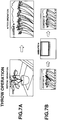
FIG. 7 shows changes of a display by the throw-based command input. -
FIG. 8 shows a flow of operations made in controlling the video display system inFIG. 1 by catch-based input of a command. -
FIG. 9 shows changes of a display by the catch-based command input. -
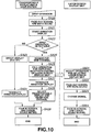
FIG. 10 shows a flow of operations made in controlling the video display system inFIG. 1 by swap-based input of a command. -
FIG. 11 shows changes of a display by the swap-based command input. - The present invention will be described in detail below concerning the embodiments thereof with reference to the accompanying drawings.
- The video display system according to the present invention is constructed as shown in
FIG. 1 by way of example. As shown, the video display system, generally indicated with areference 1, includes atransportable display unit 100, abase station 200 and a large-screen display unit 300. A video signal supplied from thebase station 200 is displayed on thetransportable display unit 100 and large-screen display unit 300. - The
transportable display unit 100 is a liquid crystal display (LCD) unit using an LCD panel 107 (as inFIG. 2 ) as a display element, while the large-screen display unit 300 uses a large-screen plasma display panel. - As shown in
FIG. 2 , thetransportable display unit 100 includes a transmission/reception antenna 101,antenna duplexer 102,reception processor 103,decoder 104, OSD (on-screen display)processor 105,video processor 106,LCD 107,audio signal amplifier 108,speaker 109,transmission signal generator 111,transmission processor 112,touch panel 121 and a coordinatedetector 122. - Each component of the
transportable display unit 100 is controlled by acontroller 130. Thecontroller 130 is a microcomputer including a CPU (central processing unit) 131, ROM (read-only memory) 132, RAM (random-access memory) 133 and an EEPROM (electrically erasable programmable read-only memory) 134, connected by aCPU bus 135 to one another. - The
ROM 132 has recorded therein a variety of processing programs to be executed in thetransportable display unit 100 and necessary data for execution of the processing programs. TheRAM 133 is used as a work area for various kinds of processing. It provisionally stores and holds data acquired by each processing, for example. - The
EEPROM 134 is a so-called nonvolatile memory to hold stored information even if the power supply is turned off. It stores and holds various set parameters, Web sites on the Internet, acquired via thebase station 200, electronic mails prepared for transmission via thebase station 200, received electronic mails, etc. - The
transportable display unit 100 operates when receiving a radio signal from thebase station 200 as will be described below. - Between the
transportable display unit 100 andbase station 200, there are made radio communications using a specified protocol such as the IEEE (Institute Electrical and Engineering Engineers) 802.11 protocol or an extended version of the latter. - The radio signal complying with the specified communication protocol is received by the transmission/
reception antenna 101 of thetransportable display unit 100 from thebase station 200 and supplied to thereception processor 103 via the antenna duplexer (will be referred to simply as "duplexer" hereunder) 102. Theduplexer 102 is provided to prevent a transmission signal and reception signal from interfering with each other. - That is, the
transportable display unit 100 can receive a signal from thebase station 200 via the transmission/reception antenna 101, and transmit an operation instruction from itself or the like by radio from the transmission/reception antenna 101. Thus, theduplexer 102 prevents a transmission signal from thetransmission processor 112 from interfering with a signal received via the transmission/reception antenna 101. - The
reception processor 103 demodulates or otherwise processes the signal supplied thereto and supplies the demodulated signal to the decoder (expander) 104. Thebase station 200 compresses, for transmission, video and audio signals of a ground-wave TV program selected by a built-in first orsecond tuner - The
decoder 104 included in thetransportable display unit 100 is supplied with the decoded compressed signal from thereception processor 103, separates it into video and audio signals, expands the separated signals, respectively, and thus reproduces the initial signal before compressed. - Then, the
decoder 104 makes a D-A conversion of the decoded video and audio signals to provide analog video and audio signals. Further thedecoder 104 supplies the analog video signal to theOSD processor 105 while supplying the analog audio signal to theaudio signal amplifier 108. - The
OSD processor 105 is a so-called text/graphic processing circuit that processes, in response to the data supplied from thecontroller 130, the video signal for display of a control-panel image and menu, various messages, and display information such as character, picture, symbol or the like other than the image of a broadcast program - For example, for display of a control-panel image in response to an instruction given by the user, information for display of the control-panel image is supplied from the
controller 130 to theOSD processor 105. In theOSD processor 105, the control-panel image from thecontroller 130 is combined with the video signal from thedecoder 104 and the data thus synthesized is supplied to the videosignal processing circuit 106. - Also, for display of character information indicative of a channel to be selected and a sound-volume bar indicative of a loudness of level of sound in response to an instruction given by the user, information for display of the data is supplied from the
controller 130 to theOSD processor 105. Then, the control-panel image from thecontroller 130 is combined with the video signal from thedecoder 104, and the data thus synthesized is supplied to thevideo signal processor 106. - Also, in case the display information such as control-panel image has not to be combined with the video signal, the video
signal processing circuit 107 is supplied with the analog video signal from thedecoder 104 as it is since no display information is supplied to theOSD processor 105. Thevideo signal processor 106 generates a display signal from the video signal supplied via theOSD processor 105 and supplies it to theLCD 107. - Thus, an image corresponding to the video signal supplied via the radio transmission from the
base station 200 is displayed on the display screen of theLCD 107. In this case, when display information such as control-panel image has been synthesized in theOSD processor 105, display information such as the control-panel image is displayed along with an image based on the video signal from thedecoder 104. - On the other hand, the
audio signal amplifier 108 amplifies the audio signal supplied thereto to a predetermined level, and supplies the amplified audio signal to thespeaker 109. Thus, thespeaker 109 outputs a sound corresponding to the audio signal transmitted by radio from thebase station 200. - As above, the
transportable display unit 100 can receive video and audio signals such as a TV broadcast program transmitted by radio from thebase station 200, reproduce the received video and audio signals and provide the user with the signals as an image and sound. - Also, the
transportable display unit 100 functions as a remote controller that accepts a command given by the user having touched and stroked thetouch panel 121 provided on the surface of theLCD 107 and sends an operation instruction corresponding to the command to thebase station 200. - That is, the
transportable display unit 100 has thetouch panel 121 attached on the surface of theLCD 107 to accept an operation instruction given by the user who touches and strokes the surface of thetouch panel 121. - Then, the
transportable display unit 100 detects, by the coordinatedetector 122, a location (coordinate position) on the surface of thetouch panel 121 attached to theLCD 107, where the user touches by the finger or the like, and discriminates the user's command entered by the finger-touch by means of thecontroller 130 on the basis of the detection output of screen-touch location from the coordinatedetector 122 to provide an operation instruction corresponding to the command. Thecontroller 130 supplies the operation instruction corresponding to the command to thetransmission signal generator 111. Thetransmission signal generator 111 generates a transmission signal for transmission to thebase station 200 from the operation instruction supplied from thecontroller 130, and supplies the transmission signal to thetransmission processor 112. Thetransmission processor 112 processes the supplied transmission signal by modulation, amplification, etc. to generate a transmission signal in an actually transmitted form, and transmits the transmission signal to thebase station 200 via theduplexer 102 and transmission/reception antenna 101. - Thus, the operation instruction transmitted by radio from the
transportable display unit 100 is received by thebase station 200. - Also, the
transportable display unit 100 has a key-input unit 141 connected thereto by an interface (I/F) 140. The key-input unit 141 is provided with an power on/off switch etc. for example. An operation instruction entered with the use of the key-input unit 141 is supplied to thecontroller 130 via the I/F 140 to turn on the power supply and make an operation corresponding to an operated control key. - As shown in
FIG. 3 , thebase station 200 included in thevideo display system 1 includes first andsecond tuners base station 200 is connected by a telephone line L to a telephone network.FIG. 3 shows a terminal MJ which is a modular jack for connection with the telephone line L led in from outside thebase station 200. Also, thebase station 200 hasexternal input terminals - In the
base station 200, video and audio signals, acquired by modulation, of a TV broadcast program received from the broadcast station selected by thefirst tuner 202A, video and audio data acquired from a communication network via its own modem, or information signals such as video and audio signals of a satellite broadcast program from an STB, can be compressed to generate a transmission signal which can be sent to thetransportable display unit 100. - Also in the
base station 200, video and audio signals, acquired by demodulation, of a TV broadcast program received from a broadcast station selected by thesecond tuner 202B, video and audio data acquired from a communication network via its own modem, or information signals such as video and audio signals of a satellite broadcast program from an STB, can be supplied from an output terminal 215 to the large-screen display unit 300 via a connection cable. - That is, as shown in
FIG. 3 , thebase station 200 includes the first andsecond tuners reception antenna demodulators signal input terminal 204, audiosignal input terminal 205,selector 206,compression unit 207,transmission signal generator 208,transmission processor 209,antenna duplexer 210, transmission/reception antenna 211,reception processor 212, etc. - Various components of the
base station 200 are controlled by acontroller 230 which is a microcomputer including aCPU 231,ROM 232,RAM 233 andEEPROM 234, connected by aCPU bus 235 to one another. - The
ROM 232 has recorded therein a variety of processing programs to be executed in thebase station 200 and necessary data for execution of the processing programs. TheRAM 233 is used as a work area for various kinds of processing. It provisionally stores and holds data acquired by each processing, for example. - The
EEPROM 234 is a so-called nonvolatile memory to hold stored information even if the power supply is turned off. It stores and holds information on a broadcast channel having been selected until the main power supply to thebase station 200 is turned off. After the power supply is turned on, theEEPROM 234 selects a broadcast signal on a channel having been selected until the last disconnection of the power supply. That is, theEEPROM 234 can provide a so-called last channel memory. - Also, the
controller 230 has amodem 220 connected thereto. Themodem 220 includes an interface (will be referred to as "I/F" hereunder) 221 andcommunication unit 222. In this embodiment, the I/F 221 provides an interface between a telephone line and thebase station 200. It receives a signal sent via the telephone line and sends a signal from thebase station 200 to the telephone line. - The
communication unit 222 demodulates a signal received via the I/F 221 and supplies it to thecontroller 230. On the other hand, it modulates a transmission signal from thecontroller 230 and supplies it to the I/F 221. Thus, thecommunication unit 222 can send and receive various kinds of data to and from a destination to which the telephone line is connected. - Also the
base station 200 can connect to the Internet via themodem 220, telephone line L and a predetermined ISP (Internet Service Provider) to be served various information via the Internet, send and receive an electronic mail. Thus, thecontroller 230 can control themodem 220 to be on hook or off hook. When controlling themodem 220 to be off hook, thecontroller 230 sends a dial signal to the telephone line. Namely, it has a function as a dialer. - Also, the
controller 230 of thebase station 200 has a remote-control signal transmitter 250 connected thereto via a remote-control signal generator 241 that sends an infra-red remote-control signal, called "remote-control mouse" and a remote-controlsignal output terminal 242. Thus, thecontroller 230 generates a remote-control signal corresponding to an operation instruction from thetransportable display unit 100 and sends it to an external unit such as an STB from the remote-control signal transmitter 250. - Note that the
controller 230 has connected thereto a key-input unit 239 having a power on/off key and various set keys provided thereon by an interface (I/F) 238. Thus, thecontroller 230 can turn on and off thebase station 200 and make various kinds of set inputs by means of the key-input unit 239. - In the
video display system 1, thefirst tuner 202A of thebase station 200 selects one of TV broadcast signals received at a reception antenna 101A, which corresponds to a channel selection instruction signal from thecontroller 230, and supplies it to ademodulator 203A. Thedemodulator 203A demodulates the supplied TV broadcast signal and supplies the demodulated signal (signals of a TV program) to theselector 206. Similarly, thesecond tuner 202B selects one of TV broadcast signals received at the reception antenna 101A, which corresponds to a channel selection instruction signal from thecontroller 230, and supplies it to thedemodulator 203B. - In addition to the video signal supplied via the video
signal input terminal 204 and audio signal supplied via theinput terminal 205, information is supplied from thecontroller 230 to theselector 206. The information supplied to theselector 206 from thecontroller 230 includes information on so-called Web sites open on the Internet, information such as electronic mail, downloaded via themodem 220. - The
selector 206 selects one of the signal output from the demodulator 203, signal output from theexternal input terminals controller 230 in response to a selection control signal from thecontroller 230. The selection control signal from thecontroller 230 to theselector 206 is generated by thecontroller 230 correspondingly to a command input sent by radio from thetransportable display unit 100. - The output from the
selector 206 is supplied to thecompression unit 207 in which the supplied signal will be compressed by a predetermined compression method. To compress the signal from theselector 206, thecompression unit 207 adopts a data compression method such as an MPEG or Wavelet method, for example. - The signal compressed by the
compression unit 207 is supplied to thetransmission signal generator 208. Thetransmission signal generator 208 generates a transmission signal in compliance with a predetermined communication protocol. In this embodiment, thebase station 200 adopts the IEEE (Institute of Electrical and Electronics Engineers) 802.11 protocol or its extension protocol to generate a transmission signal. - The transmission signal generated by the
transmission signal generator 208 is supplied to thetransmission processor 209 which will modulate and amplify the supplied transmission signal according to a control signal from thecontroller 230. The transmission signal thus processed by thetransmission processor 209 is sent by radio via theduplexer 210 and transmission/reception antenna 211. Similarly to theduplexer 102 in thetransportable display unit 100, theduplexer 210 prevents transmission and reception signals from interfering with each other. - The video and audio signals of a TV broadcast program selected by the
first tuner 202A, video and audio signals accepted via theexternal input terminals modem 220, can be supplied to thetransportable display unit 100 through the above compression and radio transmission based on a predetermined communication protocol. - Also, the video and audio signals of a TV broadcast program selected by the
second tuner 202B, video and audio signals accepted via theexternal input terminals modem 220, can be supplied to the large-screen display unit 300 over an interconnecting cable from the output terminal 215 of thebase station 200. - In the
video display system 1, since two-way communications are possible between thetransportable display unit 100 andbase station 200, the user can make remote control of an external unit via thebase station 200 by giving a command input to the external unit by touching and stroking the surface of thetouch panel 121 of thetransportable display unit 100. - Since the
transportable display unit 100 is designed compact and lightweight and connected by radio to thebase station 200, it is easily transportable. Thus, the user can use thetransportable display unit 100 anywhere within a range in which communications with thebase station 200 are possible. Thetransportable display unit 100 can reproduce information signals supplied from thebase station 200 and provide the information to the user. - Therefore, use of the
transportable display unit 100 enables the user to watch a TV broadcast program selected by the first orsecond tuner base station 200, to watch a satellite broadcast program carried by a satellite broadcast signal and selected by STB or to watch a movie that is reproduced by a VTR or DVD drive if the latter is connected as an external input unit to thebase station 200. - Also, using the
transportable display unit 100 enables the user to download and watch information on a so-called Web page provided on the Internet, for example, via the modem of thebase station 200, to receive an electronic mail addressed to him or her and display it on theLCD 107 or to prepare an electronic mail and send it to a destination. - Note that for preparation of an electronic mail, the user can operate the
transportable display unit 100 in a predetermined manner to display a software keyboard having alphabet keys or 50-character Japanese syllabary keys arranged thereon on theLCD 107. The user can use the software keyboard displayed on theLCD 107 andtouch panel 121 to prepare an electronic mail. Then, the user can send the electronic mail thus prepared to thebase station 200 by making a predetermined operation such as pressing a send key and then to a destination via thebase station 200. - As just described, the
base station 200 is a base for providing interconnection between thetransportable display unit 100 and one of various information transmission media including an external input unit such as STB, a communication network such as ground-wave TV broadcast or Internet, etc. Thetransportable display unit 100 can be supplied with information signals from thebase station 200, reproduce the signal and deliver the reproduced data to the user, while forming transmission information such as electronic mail and sending it via thebase station 200. - Also, in the
video display system 1, video and audio signals of the TV broadcast program, video and audio data downloaded from a communication network via the modem of thesystem 1 itself or information signals such as video and audio signals of a satellite broadcast program from an STB, are supplied from the output terminal 215 of thebase station 200 to the large-screen display unit 300, thereby permitting to display a desired image on the large-screen display unit 300. - In the
video display system 1, a channel select command is assigned to an operation instruction given by touching and horizontally stroking, with the finger, the surface of thetouch panel 121 provided on theLCD 107 of thetransportable display unit 100, and also a screen swap command is assigned to an operation instruction given by touching and vertically stroking, with the finger, the surface of thetouch panel 121, whereby the operation of thevideo display system 1 can be controlled as will be described below with reference toFIG. 4 . - Note that a command input by touching and stroking the surface of the
touch panel 121 with the finger will be referred to as "gesture input" hereunder. - As in the flow diagram in
FIG. 4 , when a command input, namely, a gesture input, is made by stroking the surface of thetouch panel 121 with the finger, thecontroller 130 of thetransportable display unit 100 extracts a sample point at every predetermined times and distances on the basis of a detection output of screen-touch location from the coordinate detector 122 (in step S1), and judges which the direction of a gesture indicated by the gesture input is, horizontal or vertical, on the basis of an aspect ratio of the user-made gesture, obtained from the result of extraction (in step S2). - In case the result of the judgment made in step S2 is that the gesture direction is horizontal, the
controller 130 judges whether the length of the gesture indicated by the gesture input is more than specified (in step S3). In case the result of the judgment made in step S3 is negative (NO), namely, if the gesture length is not more than specified, thecontroller 130 ignores the gesture input (in step S14) and will wait for a next gesture input (in step S15). - Also, in case the result of the judgment in step S3 is affirmative (YES), namely, if the gesture length is more than specified, the
controller 130 judges whether the duration of the gesture indicated by the gesture input is less than specified (in step S4). In case the result of the judgment in step S4 is negative (NO), namely, if the gesture duration is not less than specified, thecontroller 130 ignores the gesture input (in step S14)and will wait for a next gesture input (in step S15). - In case the result of the judgment in step S4 is affirmative (YES), namely, if the gesture duration is less than specified, the
controller 130 of thetransportable display unit 100 takes the gesture input as a channel select gesture input, and generates an operation instruction indicating a channel up command "+" or channel down command "-" correspondingly to the gesture direction indicated by the gesture input and sends it from thetransmission processor 112 to thebase station 200. Thus, thecontroller 230 of thebase station 200 makes a channel selection corresponding to the operation instruction (in step S5). For example, a channel up command "+" is assigned herein to a gesture input OPA indicated with a rightward arrow inFIG. 5 , while a channel down command "-" is assigned to a gesture OPB indicated with a leftward arrow inFIG. 5 . - Further, the
controller 130 of thetransportable display unit 100 judges the gesture input to see whether the user's finger is in touch with the surface of the touch panel 121 (PenDown state) (in step S6). In case the result of the judgment is negative (NO), namely, if there is no PenDown state, thecontroller 130 waits for a next gesture input (in step S 15) taking that the gesture input is over. - Also, if the result of the judgment in step S6 is affirmative (YES), namely, when the PenDown state is held, the
controller 130 judge, by detecting a pen coordinate, whether the selection of a channel is repeatable (in step S7). If the result of the judgment is negative (NO), namely, if the channel selection is not repeatable, thecontroller 130 waits for a next gesture input (in step S15) taking that the gesture input is over. - In case the result of the judgment in step S7 is affirmative (YES), namely if the channel selection is repeatable, the
controller 130 generates an operation instruction indicating a select command and sends it from thetransmission processor 112 to thebase station 200. Thus, thecontroller 230 of thebase station 200 makes a channel selection corresponding to the operation instruction (in step S8). By repeating the above series of operations, a channel is repeatedly selected at every predetermined times. - By taking off the finger (pen) from the
touch panel 121 or moving the pen in a direction opposite to the initial gesture direction, the result of the judgment in step S7 will be negative (NO) and the repetition of the same channel selection be canceled. - If the result of the judgment in step S2 is that the gesture direction is vertical, the
controller 130 of thetransportable display unit 100 judges which the gesture direction is, upward, downward or upward and downward (in step S9). In case the result of the judgment is negative (NO), namely, in case the gesture direction is other than upward, downward or upward and downward, thecontroller 130 ignores the gesture input (in step S14) and waits for a next gesture input (in step S15). - When the result of the judgment in step S9 is affirmative (YES), namely, if the gesture direction is upward, downward or upward and downward, the
controller 130 in thetransportable display unit 100 takes that the gesture input is a gesture input for throw, catch or swap, and judges whether the gesture length indicated by the gesture input is more than specified (in step S10). If the result of the judgment is negative (NO), namely, the gesture length is less than specified, thecontroller 130 ignores the gesture input (in step S 14) and waits for a next gesture input (in step S 15). - If the result of the judgment in step S10 is affirmative (YES), namely, if the gesture length is more than specified, the
controller 130 judges whether the gesture duration indicated by the gesture input is less than specified (in step S11). In case the result of the judgment is negative (NO), namely, if the gesture duration is less than specified, thecontroller 130 ignores the gesture input (in step S 14) and waits for a next gesture input (in step S15). - Note that the specified gesture length as in step S10 and specified gesture duration in step S11 vary depending upon which of throw, catch and swap commands is assigned to a gesture input.
- If the result of the judgment in step S10 is affirmative (YES), namely, when the gesture input duration is less than specified, the
controller 130 of thetransportable display unit 100 takes the gesture input is a gesture input for a throw, catch or swap, and generates an operation instruction indicating a throw, catch or swap command correspondingly to a gesture direction and sends it from thetransmission processor 112 to thebase station 200. - Note here that a throw command is assigned to a gesture input OP1 indicated with an upward arrow in
FIG. 5 , a catch command is assigned to a gesture input OP2 indicated with a downward arrow inFIG. 5 and a swap command is assigned to a gesture input OP3 indicated with an arrow extending downward and returning upward as inFIG. 5 . - Then the
controller 230 of thebase station 200 makes an animation correspondingly to an operation instruction (in step S12), further selects a channel and swap images (in step S13) and waits for a next gesture input (in step S15). - Here, upon reception of a throw command, the
controller 230 of thebase station 200 will make a parallel throw-control of both the transportable and large-screen display units FIG. 6 . - More specifically, for control of a throw operation, screen fade-out and sound muting are effected at the transportable display unit 100 (in step SA0), an animation display control is started (in step SA1) and it is judged whether the throw operation is possible (in step SA2). In case the result of the judgment is negative (NO), namely, if the throw operation is impossible because the
transportable display unit 100 is out of a radio communication range or thetransportable display unit 100 is locked against operation at thebase station 200, thecontroller 230 of the latter will make a malfunction indication (in step SA3), terminate the animation display control (in step SA4), fade in the screen and cancel the sound muting (in step SA7), and then exit the throw-operation control. - In case the result of the judgment in step SA2 is affirmative (YES), namely, if the throw operation is possible, the
controller 230 will call, from thetransportable display unit 100, an operation for switching the reception channel of the large-screen display unit 300 to that of the transportable display unit 100 (in step SA5), terminate the animation display control (in step SA6), fade in the screen and cancel the sound muting (in step SA7), and then exit the throw-operation control. - Upon reception of the call for the operation for switching the reception channel (in step SB1), the large-
screen display unit 300 will fade out the screen and control sound muting (in step SB2), make a signal-changing operation such as scan-rate change (in step SB3), fade in the screen and cancel the sound muting (step SB4), and then exit the throw-operation control. - With the above throw-operation control, the display on the large-
screen display unit 300 is changed to that on thetransportable display unit 100 as shown inFIG. 7A , and the throw operation will be displayed as an animation without change of the display on thetransportable display unit 100 as shown inFIG. 7B . - Also, upon reception of a catch command, the
controller 230 of thebase station 200 will make a parallel catch-control of both the transportable and large-screen display units FIG. 8 . - More specifically, for control of a catch operation, the display screen is faded out and the sounding is muted at the transportable display unit 100 (in step SA10), an animation display control is started (in step Spa11) and it is judged whether the catch operation is possible (in step SA12). In case the result of the judgment is negative (NO), namely, if the catch operation is impossible because the
transportable display unit 100 is out of a radio communication range or thetransportable display unit 100 is locked against operation at thebase station 200, thecontroller 230 of the latter will make a malfunction indication (in step SA13), terminate the animation display control (in step SA14), fade in the screen and cancel the sound muting (in step SA19), and then and exit the catch-operation control. - Also, in case the result of the judgment in step SA12 is affirmative (YES), namely, if the catch operation is possible, the
controller 230 will catch the reception channel of the large-screen display unit 300 from the transportable display unit 100 (in step SA15), call, from thetransportable display unit 100, an operation for switching the reception channel of the large-screen display unit 300 (in step SA16), terminate the animation display control (in step SA17), execute the operation for switching the reception channel of thetransportable display unit 100 to that of the large-screen display unit 300, having been caught in step SA15 (in step SA18), fade in the screen and cancel the sound muting (in step SA19), and then exit the catch-operation control. - Upon reception of the call for the operation for switching the reception channel (in step SB11), the large-
screen display unit 300 will display, by OSD, that the reception channel has been caught by thetransportable display unit 100 for a predetermined length of time (in step SB12), and cancel the OSD display of the catching of the reception channel (in step SB14), with no channel switching, and then exit the catch-operation control. - With the above catch-operation control, the large-
screen display unit 300 will display an OSD display as shown inFIG. 9A , and the display at thetransportable display unit 100 will be changed to a display at the large-screen display unit 300 through display of an animation display as shown inFIG. 9B . - Further, upon reception of a swap command, the
controller 230 of thebase station 200 will make a parallel swap-control of both the transportable and large-screen display units FIG. 10 . - More specifically, for control of a swap operation, the screen is faded out and the sound is muted at the transportable display unit 100 (in step SA20), an animation display control is started (in step SA21) and it is judged whether the swap operation is possible (in step SA22). In case the result of the judgment is negative (NO), namely, if the swap operation is impossible because the
transportable display unit 100 is out of a radio communication range or thetransportable display unit 100 is locked against operation at thebase station 200, thecontroller 230 of the latter will make a malfunction indication (in step SA23), terminate the animation display control (in step SA24), fade in the screen and cancel the sound muting (in step SA29), and then exit the swap-operation control. - Also, in case the result of the judgment in step SA22 is affirmative (YES), namely, if the swap operation is possible, the
controller 230 will catch the reception channel of the large-screen display unit 300 from the transportable display unit 100 (in step SA25), call, from thetransportable display unit 100, an operation for switching the reception channel of the large-screen display unit 300 to that of the transportable display unit 100 (in step SA26), terminate the animation display control (in step SA27), execute the operation for switching the reception channel of thetransportable display unit 100 to that of the large-screen display unit 300, having been caught in step SA25 (in step SA28), fade in the screen and cancel the sound muting (in step SA29), and then exit the swap-operation control. - Upon reception of the call for the operation for switching the reception channel (in step SB21), the large-
screen display unit 300 will fade in the screen and control the sound muting (in step SB22), execute the signal switching operation such as scan rate change (in step SB23), fade in the screen and cancel the sound muting (in step SB24), and then exit the swap-operation control. - With the above swap-operation control, the display at the large-
screen display unit 300 is changed to a display at thetransportable display unit 100 as shown inFIG. 11A , and the display at thetransportable display unit 100 is changed to a display at the large-screen display unit 300 via an animation display as shown inFIG. 11B . - In the aforementioned embodiment, the
first tuner 202A of thebase station 200 controls a screen swap operation to make swapping between thetransportable display unit 100 and large-screen display unit 300 for display of a TV broadcast program selected by thesecond tuner 202B. Namely, the control of the throw-operation, catch-operation and swap-operation has been described in the foregoing. In thevideo display system 1, it is also possible to make swapping between thetransportable display unit 100 and large-screen display unit 300 similarly by operating theselector 206 for display of a satellite broadcast program provided as a satellite broadcast signal selected by STB or a movie reproduced by a VTR or DVD drive, if any connected as an external input device to thebase station 200. - Also in the
video display system 1, theOSD processor 105 displays a control panel as shown inFIG. 5 for thetransportable display unit 100 on the display screen of theLCD 107 on which thetouch panel 121 is provided, and thecontroller 130 of thetransportable display unit 100 accepts a user's operation of a throw button TB, catch button CB or swap button SB on the control panel to generate a throw command, catch command or swap command. Thus, a throw, catch or swap operation can be controlled correspondingly to the button operation, not to any gesture input. - Also in the
video display system 1, a lock switch provided at the key-input unit 239 of thebase station 200 can be used not to accept any throw-, catch- or swap-operation control based on the gesture input or button operation. - Note here that although the aforementioned
video display system 1 according to the embodiment of the present invention includes thetransportable display unit 100,base station 200 and large-screen display unit 300 and is designed to display a video signal supplied from thebase station 200 at thetransportable display unit 100 and large-screen display unit 300, thebase station 200 may supply a video signal by radio or cable transmission to a plurality oftransportable display units 100 as well as to a plurality of large-screen display units 300. - In the
video display system 1 including at least the twodisplay units base station 200 which supplies a video signal to the twodisplay units controller 130 of thetransportable display unit 100 generates an operation instruction for selection of an image for display, corresponding to the direction of a user's touch on the display screen surface, on the basis of a detection output of screen-touch location from the screen-touch positioning means (touch panel 121 and coordinate detector 122) provided on the display screen of the image display (LCD 107) of thetransportable display unit 100 which displays an image corresponding to the video signal supplied from thebase station 200 and that detects the location of the touch on the display screen surface the user touches with the finger or the like, and sends the operation instruction from the two-way communication means (transmission processor 112) to thebase station 200, and thecontroller 230 of thebase station 200 controls at least the twotuners base station 200 and each capable of selecting a reception channel independently of each other in response to the to-be-displayed image selecting operation instruction, to select a channel. Thus, for supply of a video signal from the base station to a plurality of display units, the user can transfer a video signal between the base station and plurality of display units by stroking the display screen with the finger, and intuitively make an operation selection quite different from that by a button on the conventional remote controller. - In the aforementioned
video display system 1 according to the present invention, the touched positioning means includes thetouch panel 121 and the coordinatedetector 122 that recognizes the location of a touch on the surface of thetouch panel 121 as a coordinate position. In response to a gesture input made by stroking, with the finger, the surface of thetouch panel 121, thecontroller 130 of thetransportable display unit 100 extracts samples at every fixed times or distances from a detection output from the coordinatedetector 122, judges, based on an aspect ratio of the stroke, in which direction the stroking has been made, horizontal or vertical, and generate generates a screen select instruction corresponding to a direction in which the user has stroked the display screen surface with the finger. - Also, in the aforementioned
video display system 1 according to the present invention, the operation instruction generating means, that is, thecontroller 130 of thetransportable display unit 100, generates a screen select instruction corresponding to the direction of a user's finger stroke taken as a valid one when the stroking is larger in length than specified and shorter in duration than specified, for example. - In the
transportable display unit 100, the operation instruction generating means (controller 130) can control the channel selecting operation of the twotuners base station 200 to thedisplay units transportable display unit 100 to thebase station 200 via the two-way communication means (transmission processor 112). - Also, in the
transportable display unit 100, thecontroller 130 can make a channel selection control to set the reception channel of thetuner 202A that supplies a video signal from thebase station 200 to thedisplay unit 100 to that of thetuner 202B that supplies a video signal from thebase station 200 to theother display unit 300 by generating an operation instruction resulted from assignment of a screen change command (throw command) to a vertical finger stroke on the display screen surface on the basis of a detection output of screen-touch location from the screen-touch positioning means (touch panel 121 and coordinate detector 122), and sending it from thedisplay unit 100 to thebase station 200 via the two-way communication means (transmission processor 112). - Also, in the
transportable display unit 100, thecontroller 130 can make a channel selection control to set the reception channel of thetuner 202B that supplies a video signal from thebase station 200 to thedisplay unit 300 to that of thetuner 202A that supplies a video signal from thebase station 200 to theother display unit 100 by generating an operation instruction resulted from assignment of a screen change command (catch command) to a vertical finger stroke on the display screen surface on the basis of a detection output of screen-touch location from the touch positioning means (touch panel 121 and coordinate detector 122), and sending it from thedisplay unit 100 to thebase station 200 via the two-way communication means (transmission processor 112). - Also, in the
transportable display unit 100, thecontroller 130 can make a channel selection control to swap the reception channel of thetuner 202A that supplies a video signal from thebase station 200 to thedisplay unit 100 with that of thetuner 202B that supplies a video signal from thebase station 200 to theother display unit 300 by generating an operation instruction resulted from assignment of a screen change command (swap command) to a vertical finger stroke on the display screen surface on the basis of a detection output of screen-touch location from the screen-touch positioning means (touch panel 121 and coordinate detector 122), and sending it from thedisplay unit 100 to thebase station 200 via the two-way communication means. - Also in the
transportable display unit 100, when the user strokes the display screen surface with the finger upward, downward or downward and upward, for example, thecontroller 130 generates an operation instruction formed with one of first to third screen select commands (throw, catch and swap) assigned to the finger stroke correspondingly to the direction of as user's finger stroke. With an operation instruction formed with the first screen select command (throw) assigned to the finger stroke, a channel selection is made to set the reception channel of thetuner 202A that supplies a video signal from thebase station 200 to thedisplay unit 100 to that of thetuner 202B that supplies a video signal from thebase station 200 to theother display unit 300. With an operation instruction formed with the second screen select command (catch) assigned to the finger stroke, a channel selection is made to set the reception channel of thetuner 202B that supplies a video signal from thebase station 200 to theother display unit 300 to that of thetuner 202A that supplies a video signal from thebase channel 200 to thedisplay unit 100. With an operation instruction formed with the third screen select command (swap) assigned to the finger stroke, a channel selection is made to swap the reception channel of thetuner 202A that supplies a video signal from thebase station 200 to thedisplay unit 100 with that of thetuner 202B that supplies a video signal from thebase station 200 to theother display unit 300. - Further in the
video display system 1 according to the present invention, thetransportable display unit 100 can display an animation indicating that a display screen has been selected by swapping corresponding to a screen select command. - Further in the
video display system 1 according to the present invention, upon reception of a call for a reception channel selection based on the screen select command, theother display unit 300 can fade out the screen and control the sound muting, select a signal, and fade in the screen and cancel the sound muting. - Also, in the
video display system 1 including at least the twodisplay units base station 200 which supplies to the twodisplay units controller 130 of thetransportable display unit 100 generates an operation instruction for selection of an image for display, which corresponds to a direction in which the user has stroked the display screen surface, on the basis of a detection output of screen-touch location from the screen-touch positioning means (touch panel 121 and coordinate detector 122) provided on the display screen of the image display (LCD 107) of thetransportable display unit 100 which displays an image corresponding to the video signal supplied from thebase station 200 and that detects the location of the touch on the display screen surface the user touches with the finger or the like, and sends the operation instruction from the two-way communication means (transmission processor 112) to thebase station 200, and thecontroller 230 of thebase station 200 controls theselector 206 provided at thebase station 200 in response to the to-be-displayed image selecting operation instruction, thereby permitting to selectively output a signal from the demodulator 203, theexternal input terminals controller 230. For supply of a video signal from the base station to a plurality of display units, the user can transfer a video signal between the base station and plurality of display units by stroking a display screen with the finger, and intuitively make an operation selection quite different from that by a button on the conventional remote controller. Also in this case, when the user strokes the display screen surface with the finger upward, downward or downward and upward, thetransportable display unit 100 can generate, by thecontroller 130, an operation instruction formed with one of first to third screen select commands (throw, catch and swap) assigned to the finger stroke correspondingly to the direction of a user's finger stroke to select one of various display screens. - In the foregoing, the present invention has been described in detail concerning certain preferred embodiments thereof as examples with reference to the accompanying drawings. However, it should be understood by those ordinarily skilled in the art that the present invention is not limited to the embodiments but can be modified in various manners, constructed alternatively or embodied in various other forms without departing from the scope thereof as set forth and defined in the appended claims.
Claims (9)
- A video display system (1) comprising at least a first and second display unit (100, 300) and a base station (200) that supplies a video signal to the first and second display units, in which:the base station includes:(a) at least a first and second tuning means (202A, 202B) each capable of selecting a reception channel independently of each other;(b) a video signal output means for supplying a video signal on the reception channel selected by each of the minimum of two tuning means to the minimum of two display units;(c) a two-way communication means for transferring information signals to and from at least one of the minimum of two display units; and(d) a control means (206) for controlling the minimum of two tuning means, andat least the first display unit (100) which transfers information signals to and from the base station includes:i. a two-way communication means (102) for transferring the information signals to and from the base station;ii. a video display (107) for displaying an image corresponding to the video signal supplied from the base station;iii. a screen-touch positioning means (121) provided on a display screen of the video display for recognition of the location of a touch the user gives with the finger on the surface of the display screen;characterised in that the first display unit (100) further includes:iv. an operation instruction generating means for judging a direction of a user's finger stroke based on an aspect ratio of the finger stroke, and for generating a display-image select instruction corresponding to the direction of the user's finger stroke on the basis of a detection output of screen-touch location from the screen-touch positioning means,wherein the two-way communication means of the base station is operable to receive the display-image select instruction generated by the operation instruction generating means, and the controlling means in the base station is operable to control the channel selecting operation of the first and second tuning means according to the display-image select instruction;wherein the first display unit (100) is a transportable display unit associated with the first tuning means (202A) and the second display unit (300) is a large-screen display unit associated with the second tuning means (202B), wherein the first display unit (100) has the operation instruction generating means generate an operation instruction formed with a screen swap command assigned to a vertical stroke on the basis of a detection output of screen-touch location from the screen-touch positioning means (121), and transmits the operation instruction to the base station via the two-way communication means, wherein in response to said operation instruction the controlling means controls the channel selection for setting the reception channel of the second tuning means (202B) that supplies a video signal from the base station to the second display unit (300) to that of the first tuning means (202A) that supplies a video signal from the base station to the first display unit (100).
- The video display system according to claim 1 wherein the screen-touch positioning
means includes a touch panel and a coordinate detector that recognizes the location of the user's touch on the display screen as a coordinate position, extracts sample points at every fixed times or distances from a detection output given by the coordinate detector correspondingly to a user's stroking of the touch panel, judges, based on an aspect ratio of the user's stroking, in which direction the stroking has been made, horizontal or vertical, and has the operation instruction generating means generate a display-image select instruction corresponding to the result of the judgment. - The video display system according to claim 2, wherein the operation instruction generating means generates a display-image select instruction corresponding to the direction of a user's stroking taken as a valid one when the stroke is larger in length than specified and shorter in duration than specified.
- The video display system according to claim 2, wherein the first display unit has the operation instruction generating means generate an operation instruction formed with a channel select command assigned to a horizontal stroke, to thereby control the channel selecting operation of the tuning means that supplies a video signal from the base station to the first display unit.
- The video display system according to claim 2, wherein the first display unit has the operation instruction generating means generate, in case the user strokes the display screen with the finger upwards downward or downward and upward, an operation instruction formed with any of first to third screen swap commands assigned to the finger stroke, as a display-image select instruction corresponding to the stroking direction, to thereby control the channel selection for setting, according to the operation instruction formed with the first screen swap command assigned to the finger stroke, the reception channel of the first tuning means that supplies a video signal from the base station to the first display unit to that of the second tuning means that supplies a video signal from the base station to the second display unit; control the channel selection for setting, according to the operation instruction formed with the second screen swap command assigned to the finger stroke, the reception channel of the second tuning means that supplies a video signal from the base station to the second display unit to that of the first tuning means that supplies a video signal from the base station to the first display unit; and control the channel selection for swapping, according to the operation instruction formed with the third screen swap command assigned to the finger stroke, the reception channel of the first tuning means that supplies a video signal from the base station to the first display unit with that of the second tuning means that supplies a video signal from the base station to the second display unit.
- The video display system according to claim 5, wherein the first display unit provides an animation display indicating that a screen swapping has been made correspondingly to the first to third screen swap commands.
- The video display system according to claim 1, wherein the first display unit has the operation instruction generating means generate an operation instruction formed with a channel select command assigned to a horizontal stroke on the basis of a detection output of screen-touch location from the screen-touch positioning means, and transmits the operation instruction to the base station via the two-way communication means, to thereby control the channel selecting operation of the first tuning means that supplies a video signal from the base station to the first display unit.
- The video display system according to claim 1, wherein the first display unit judges whether a screen swapping corresponding to the vertical stroke is possible and generates an operation instruction formed with the screen swap command assigned to the finger stroke when the screen swap operation is possible, to thereby call an operation for selection of the reception channel of the second display unit and provide an animation display indicating that a screen swapping corresponding to the vertical stroke has been made.
- The video display system according to claim 8, wherein receiving a call for an operation for selection of a reception channel selection under the screen swap command, the second display unit controls screen fade-out and sound muting and makes a signal selection to fade in the screen and cancel the sound muting.
Applications Claiming Priority (3)
| Application Number | Priority Date | Filing Date | Title |
|---|---|---|---|
| JP2002137774 | 2002-05-13 | ||
| JP2002137774A JP3925297B2 (en) | 2002-05-13 | 2002-05-13 | Video display system and video display control device |
| PCT/JP2003/005908 WO2003096678A1 (en) | 2002-05-13 | 2003-05-12 | Video display system and video display control apparatus |
Publications (3)
| Publication Number | Publication Date |
|---|---|
| EP1505825A1 EP1505825A1 (en) | 2005-02-09 |
| EP1505825A4 EP1505825A4 (en) | 2006-09-27 |
| EP1505825B1 true EP1505825B1 (en) | 2018-02-21 |
Family
ID=29416821
Family Applications (1)
| Application Number | Title | Priority Date | Filing Date |
|---|---|---|---|
| EP03721089.5A Expired - Lifetime EP1505825B1 (en) | 2002-05-13 | 2003-05-12 | Video display system and video display control apparatus |
Country Status (6)
| Country | Link |
|---|---|
| US (1) | US7477321B2 (en) |
| EP (1) | EP1505825B1 (en) |
| JP (1) | JP3925297B2 (en) |
| KR (1) | KR100996063B1 (en) |
| CN (1) | CN100373916C (en) |
| WO (1) | WO2003096678A1 (en) |
Families Citing this family (70)
| Publication number | Priority date | Publication date | Assignee | Title |
|---|---|---|---|---|
| JP4109902B2 (en) * | 2002-05-27 | 2008-07-02 | キヤノン株式会社 | Display device |
| JP4332707B2 (en) * | 2003-05-12 | 2009-09-16 | ソニー株式会社 | Operation input reception device, operation input reception method, and remote operation system |
| JP4003746B2 (en) * | 2004-01-07 | 2007-11-07 | ソニー株式会社 | Display device |
| US7237202B2 (en) * | 2004-05-11 | 2007-06-26 | Cynthia Joanne Gage | Multiple document viewing apparatus and user interface |
| CN100366076C (en) * | 2004-06-15 | 2008-01-30 | 南京Lg新港显示有限公司 | Wireless image system and its control |
| KR100685992B1 (en) * | 2004-11-10 | 2007-02-23 | 엘지전자 주식회사 | Method for information outputting during channel Change in digital broadcasting receiver |
| CN100508554C (en) * | 2004-12-22 | 2009-07-01 | 索尼株式会社 | Remote control system, remote commander, and remote control server |
| JP4984545B2 (en) * | 2005-05-18 | 2012-07-25 | ソニー株式会社 | Content display reproduction system and content display reproduction method |
| JP4385996B2 (en) | 2005-05-23 | 2009-12-16 | ソニー株式会社 | Content display / playback system, content display / playback method, recording medium recording content display / playback program, and operation control apparatus |
| JP4715535B2 (en) | 2005-05-23 | 2011-07-06 | ソニー株式会社 | Content display / playback system, content display / playback method, recording medium recording content display / playback program, and operation control apparatus |
| JP5055769B2 (en) * | 2005-05-23 | 2012-10-24 | ソニー株式会社 | Content display / playback system, content display / playback method, recording medium, and operation control apparatus |
| JP4385995B2 (en) * | 2005-05-23 | 2009-12-16 | ソニー株式会社 | Content display / playback system, content display / playback method, recording medium recording content display / playback program, and operation control apparatus |
| WO2007000455A1 (en) * | 2005-06-27 | 2007-01-04 | Rok Productions Limited | Channel change on mobile device |
| KR101114688B1 (en) * | 2005-07-29 | 2012-02-29 | 삼성전자주식회사 | Remote control apparatus and method in mobile communication terminal equipment |
| WO2007052625A1 (en) * | 2005-10-31 | 2007-05-10 | Matsushita Electric Industrial Co., Ltd. | Audiovisual system |
| US9247175B2 (en) * | 2005-11-30 | 2016-01-26 | Broadcom Corporation | Parallel television remote control |
| JP4997947B2 (en) * | 2006-01-05 | 2012-08-15 | ソニー株式会社 | Information processing apparatus and method, and program |
| US7699229B2 (en) * | 2006-01-12 | 2010-04-20 | Broadcom Corporation | Laptop based television remote control |
| JP2007201693A (en) * | 2006-01-25 | 2007-08-09 | Olympus Imaging Corp | Camera and camera control method |
| CN2938633Y (en) * | 2006-08-23 | 2007-08-22 | 益美科研有限公司 | Remote control system of portable device |
| US9088747B2 (en) | 2006-09-12 | 2015-07-21 | Sony Corporation | Video display system, video display device, its control method, and information storage medium |
| JP4897404B2 (en) * | 2006-09-12 | 2012-03-14 | 株式会社ソニー・コンピュータエンタテインメント | VIDEO DISPLAY SYSTEM, VIDEO DISPLAY DEVICE, ITS CONTROL METHOD, AND PROGRAM |
| JP4588005B2 (en) * | 2006-09-14 | 2010-11-24 | シャープ株式会社 | Communication terminal device, video display device, and control program |
| KR20080057082A (en) * | 2006-12-19 | 2008-06-24 | 삼성전자주식회사 | Remote controller and image system comprising the same, controlling method |
| KR101280510B1 (en) * | 2007-01-03 | 2013-07-01 | 삼성전자주식회사 | Method for channel switching and Apparatus for performing the method |
| JP5194673B2 (en) | 2007-09-26 | 2013-05-08 | 株式会社日立製作所 | Mobile terminal and information transmission / reception method |
| CN101403961B (en) * | 2007-10-12 | 2011-09-14 | 硅谷数模半导体(北京)有限公司 | User operation responding and processing system and method for computer system |
| US8517829B2 (en) * | 2008-01-08 | 2013-08-27 | Bally Gaming, Inc. | Gaming machine having interchangeable display content and methods |
| KR101203426B1 (en) * | 2008-04-23 | 2012-11-21 | 삼성전자주식회사 | Image recording/playing device and method for processing fade of the same |
| JP2010041220A (en) * | 2008-08-01 | 2010-02-18 | Canon Inc | Data processor, data processing method, and program |
| KR101588660B1 (en) * | 2008-09-30 | 2016-01-28 | 삼성전자주식회사 | A display apparatus capable of moving image and the method thereof |
| KR20100048090A (en) * | 2008-10-30 | 2010-05-11 | 삼성전자주식회사 | Interface apparatus for generating control command by touch and motion, interface system including the interface apparatus, and interface method using the same |
| KR101635640B1 (en) | 2008-12-11 | 2016-07-05 | 삼성전자 주식회사 | Display apparatus, display system and control method thereof |
| US20100153996A1 (en) * | 2008-12-17 | 2010-06-17 | Migos Charles J | Gesture based electronic program management system |
| JP5233708B2 (en) * | 2009-02-04 | 2013-07-10 | ソニー株式会社 | Information processing apparatus, information processing method, and program |
| JP5695819B2 (en) | 2009-03-30 | 2015-04-08 | 日立マクセル株式会社 | TV operation method |
| JP2011114378A (en) * | 2009-11-24 | 2011-06-09 | Canon Inc | Video display system and method of controlling the same |
| US20120054637A1 (en) * | 2010-08-27 | 2012-03-01 | Nokia Corporation | Method, apparatus, computer program and user interface |
| US20120062471A1 (en) * | 2010-09-13 | 2012-03-15 | Philip Poulidis | Handheld device with gesture-based video interaction and methods for use therewith |
| CN103492978B (en) * | 2010-10-05 | 2017-02-15 | 西里克斯系统公司 | Touch support for remoted applications |
| US8863196B2 (en) | 2010-11-30 | 2014-10-14 | Sony Corporation | Enhanced information on mobile device for viewed program and control of internet TV device using mobile device |
| US8958018B2 (en) * | 2010-12-22 | 2015-02-17 | Google Technology Holdings LLC | Remote control device and method for controlling operation of a media display system |
| JP2014064048A (en) | 2011-01-27 | 2014-04-10 | Panasonic Corp | Network control system, network control apparatus, network controlled apparatus and apparatus control method |
| JP5607579B2 (en) * | 2011-06-03 | 2014-10-15 | 任天堂株式会社 | Information processing system, information processing apparatus, information processing program, and content reproduction control method |
| JP5755943B2 (en) | 2011-06-03 | 2015-07-29 | 任天堂株式会社 | Information processing program, information processing apparatus, information processing system, and information processing method |
| US20130031585A1 (en) * | 2011-07-29 | 2013-01-31 | Hitachi Consumer Electronics Co., Ltd. | Portable terminal, system, information processing method and program |
| KR20140044881A (en) * | 2011-08-05 | 2014-04-15 | 톰슨 라이센싱 | Video peeking |
| US20130104160A1 (en) * | 2011-10-24 | 2013-04-25 | The Directv Group, Inc. | Method and system for using a second screen device to tune a set top box to display content playing on the second screen device |
| US11197064B2 (en) | 2011-12-28 | 2021-12-07 | Saturn Licensing Llc | Display device, display control method, and program |
| US9161035B2 (en) | 2012-01-20 | 2015-10-13 | Sony Corporation | Flexible band offset mode in sample adaptive offset in HEVC |
| US20130234984A1 (en) | 2012-03-06 | 2013-09-12 | Industry-University Cooperation Foundation Hanyang University | System for linking and controlling terminals and user terminal used in the same |
| CN103366659B (en) * | 2012-03-26 | 2016-07-06 | 联想(北京)有限公司 | Display control method and relevant device |
| JP5422694B2 (en) * | 2012-04-11 | 2014-02-19 | 株式会社東芝 | Information processing apparatus, command execution control method, and command execution control program |
| CN103458203B (en) * | 2012-06-05 | 2019-02-05 | 联想(北京)有限公司 | Terminal device and video display control method |
| KR101911803B1 (en) | 2012-08-10 | 2018-10-26 | 삼성전자주식회사 | Portable terminal apparatus and method of operating thereof |
| KR20140091356A (en) * | 2013-01-11 | 2014-07-21 | 삼성전자주식회사 | Display apparatus, terminal and video prividing method using display apparatus |
| CN103179465A (en) * | 2013-03-22 | 2013-06-26 | 广东欧珀移动通信有限公司 | Method for controlling video playing progress and mobile terminal |
| US9173000B2 (en) * | 2013-04-12 | 2015-10-27 | Sony Corporation | Automatic discovery and mirroring of server-client remote user interface (RUI) session on a companion device and synchronously controlling both sessions using RUI on companion device |
| US10474240B2 (en) * | 2013-06-10 | 2019-11-12 | Honeywell International Inc. | Frameworks, devices and methods configured for enabling gesture-based interaction between a touch/gesture controlled display and other networked devices |
| KR102189679B1 (en) | 2013-07-12 | 2020-12-14 | 삼성전자주식회사 | Portable appratus for executing the function related to the information displyed on screen of external appratus, method and computer readable recording medium for executing the function related to the information displyed on screen of external appratus by the portable apparatus |
| JP5780611B2 (en) * | 2013-09-30 | 2015-09-16 | Kddi株式会社 | Image display method, video processing system, portable terminal, and portable terminal operation program |
| JP2015106907A (en) * | 2013-12-03 | 2015-06-08 | 株式会社リコー | Image output system, image output method, and program |
| US9594482B2 (en) | 2014-04-07 | 2017-03-14 | The Directv Group, Inc. | Method and system for transferring the display of content from a first device to a second device |
| JP5807089B2 (en) * | 2014-05-22 | 2015-11-10 | 任天堂株式会社 | Information processing system, information processing apparatus, information processing program, and content reproduction control method |
| KR20160019693A (en) * | 2014-08-12 | 2016-02-22 | 삼성전자주식회사 | User terminal apparatus, display apparatus, system and control method thereof |
| JP2015159551A (en) * | 2015-03-19 | 2015-09-03 | シャープ株式会社 | Image display apparatus, control method of the same, television receiver, program, and recording medium |
| TWI539291B (en) | 2015-03-23 | 2016-06-21 | 奇揚網科股份有限公司 | Mirroring transmission method |
| JP6176764B1 (en) * | 2016-11-28 | 2017-08-09 | 一般社団法人日本ケーブルラボ | Television viewing operation method, set top box, terminal, and program |
| EP3570536A1 (en) * | 2018-05-17 | 2019-11-20 | InterDigital CE Patent Holdings | Method for processing a plurality of a/v signals in a rendering system and associated rendering apparatus and system |
| CN112543359B (en) * | 2020-11-12 | 2023-01-20 | 海信视像科技股份有限公司 | Display device and method for automatically configuring video parameters |
Citations (2)
| Publication number | Priority date | Publication date | Assignee | Title |
|---|---|---|---|---|
| EP0967797A2 (en) * | 1998-06-26 | 1999-12-29 | Sharp Kabushiki Kaisha | An image display and remote control system capable of displaying two distinct images |
| US6097441A (en) * | 1997-12-31 | 2000-08-01 | Eremote, Inc. | System for dual-display interaction with integrated television and internet content |
Family Cites Families (17)
| Publication number | Priority date | Publication date | Assignee | Title |
|---|---|---|---|---|
| JPH0576067A (en) * | 1991-09-11 | 1993-03-26 | Matsushita Electric Ind Co Ltd | Remote control transmitter |
| JPH09298677A (en) * | 1996-05-07 | 1997-11-18 | Matsushita Electric Ind Co Ltd | Video display device |
| US6456334B1 (en) * | 1999-06-29 | 2002-09-24 | Ati International Srl | Method and apparatus for displaying video in a data processing system |
| US6701526B1 (en) * | 1999-07-01 | 2004-03-02 | Koninklijke Philips Electronics N.V. | Method and apparatus for capturing broadcast EPG data for program title display |
| US6396523B1 (en) * | 1999-07-29 | 2002-05-28 | Interlink Electronics, Inc. | Home entertainment device remote control |
| JP2001069475A (en) * | 1999-08-27 | 2001-03-16 | Pioneer Electronic Corp | Terminal for cable television |
| JP3609663B2 (en) * | 1999-09-30 | 2005-01-12 | 三洋電機株式会社 | Digital broadcast receiving system |
| US7036083B1 (en) * | 1999-12-14 | 2006-04-25 | Microsoft Corporation | Multimode interactive television chat |
| JP4543513B2 (en) * | 2000-07-17 | 2010-09-15 | ソニー株式会社 | Bidirectional communication system, display device, base device, and bidirectional communication method |
| JP4881503B2 (en) | 2000-09-19 | 2012-02-22 | ソニー株式会社 | Command processing method and wireless communication device |
| KR20100008378A (en) * | 2001-08-08 | 2010-01-25 | 톰슨 라이센싱 | Mpeg-4 remote communication device |
| DE10224536B4 (en) * | 2002-05-31 | 2009-04-23 | Harman Becker Automotive Systems (Xsys Division) Gmbh | Method and circuit arrangement for multipath reception |
| JP2006508618A (en) * | 2002-12-02 | 2006-03-09 | 松下電器産業株式会社 | Portable device for viewing real-time synchronized information sent from broadcast sources |
| US20040152414A1 (en) * | 2003-02-04 | 2004-08-05 | Wang David S. | Remote control device capable of receiving video signal through a television tuner and displaying the video signal |
| EP1447928A1 (en) * | 2003-02-13 | 2004-08-18 | Harman/Becker Automotive Systems (Becker Division) GmbH | Receiver for TV and/or radio programs and method for monitoring TV and/or radio programs |
| US8887209B2 (en) * | 2003-09-05 | 2014-11-11 | Echostar Technologies L.L.C. | Pairing a remote control and a television |
| US7290698B2 (en) * | 2004-08-25 | 2007-11-06 | Sony Corporation | Progress bar with multiple portions |
-
2002
- 2002-05-13 JP JP2002137774A patent/JP3925297B2/en not_active Expired - Lifetime
-
2003
- 2003-05-12 EP EP03721089.5A patent/EP1505825B1/en not_active Expired - Lifetime
- 2003-05-12 KR KR1020047018309A patent/KR100996063B1/en active IP Right Grant
- 2003-05-12 US US10/514,008 patent/US7477321B2/en active Active
- 2003-05-12 CN CNB038164779A patent/CN100373916C/en not_active Expired - Fee Related
- 2003-05-12 WO PCT/JP2003/005908 patent/WO2003096678A1/en active Application Filing
Patent Citations (2)
| Publication number | Priority date | Publication date | Assignee | Title |
|---|---|---|---|---|
| US6097441A (en) * | 1997-12-31 | 2000-08-01 | Eremote, Inc. | System for dual-display interaction with integrated television and internet content |
| EP0967797A2 (en) * | 1998-06-26 | 1999-12-29 | Sharp Kabushiki Kaisha | An image display and remote control system capable of displaying two distinct images |
Also Published As
| Publication number | Publication date |
|---|---|
| US20050174489A1 (en) | 2005-08-11 |
| CN1669297A (en) | 2005-09-14 |
| JP2003333359A (en) | 2003-11-21 |
| WO2003096678A1 (en) | 2003-11-20 |
| EP1505825A1 (en) | 2005-02-09 |
| KR20040106539A (en) | 2004-12-17 |
| EP1505825A4 (en) | 2006-09-27 |
| JP3925297B2 (en) | 2007-06-06 |
| CN100373916C (en) | 2008-03-05 |
| KR100996063B1 (en) | 2010-11-22 |
| US7477321B2 (en) | 2009-01-13 |
Similar Documents
| Publication | Publication Date | Title |
|---|---|---|
| EP1505825B1 (en) | Video display system and video display control apparatus | |
| US7610600B2 (en) | Television reception system, channel selection apparatus and display apparatus | |
| USRE44391E1 (en) | Apparatus and method of interacting with a mobile phone using a TV system | |
| US7071896B2 (en) | Bi-directional communication system, display apparatus, base apparatus and bi-directional communication method | |
| JP4553882B2 (en) | Portable electronic devices, television receivers, television receiver operation systems | |
| JP2004040656A (en) | Image display system, image display method, and display device | |
| JP2004336597A (en) | Device and method for accepting operation input, and remote control system | |
| US20040095268A1 (en) | Broadcast receiving apparatus, code signal output device, and broadcast receiving apparatus control method | |
| KR19980079126A (en) | Internet television | |
| JP2006279995A (en) | Base apparatus, control method for external input apparatus, control program for external input apparatus, and recording medium recorded with control program for external input apparatus |
Legal Events
| Date | Code | Title | Description |
|---|---|---|---|
| PUAI | Public reference made under article 153(3) epc to a published international application that has entered the european phase |
Free format text: ORIGINAL CODE: 0009012 |
|
| 17P | Request for examination filed |
Effective date: 20041112 |
|
| AK | Designated contracting states |
Kind code of ref document: A1 Designated state(s): AT BE BG CH CY CZ DE DK EE ES FI FR GB GR HU IE IT LI LU MC NL PT RO SE SI SK TR |
|
| RBV | Designated contracting states (corrected) |
Designated state(s): DE FR GB |
|
| A4 | Supplementary search report drawn up and despatched |
Effective date: 20060824 |
|
| 17Q | First examination report despatched |
Effective date: 20101018 |
|
| REG | Reference to a national code |
Ref country code: DE Ref legal event code: R079 Ref document number: 60350977 Country of ref document: DE Free format text: PREVIOUS MAIN CLASS: H04N0005000000 Ipc: H04N0005440000 |
|
| RIC1 | Information provided on ipc code assigned before grant |
Ipc: H04N 5/44 20110101AFI20170616BHEP Ipc: H04N 21/422 20110101ALI20170616BHEP Ipc: H04N 21/442 20110101ALI20170616BHEP Ipc: H04N 21/426 20110101ALI20170616BHEP Ipc: H04N 5/50 20060101ALI20170616BHEP Ipc: H04N 21/438 20110101ALI20170616BHEP Ipc: H04N 21/41 20110101ALI20170616BHEP Ipc: G06F 3/0488 20130101ALI20170616BHEP Ipc: H04N 5/38 20060101ALI20170616BHEP |
|
| GRAP | Despatch of communication of intention to grant a patent |
Free format text: ORIGINAL CODE: EPIDOSNIGR1 |
|
| RAP1 | Party data changed (applicant data changed or rights of an application transferred) |
Owner name: SATURN LICENSING LLC |
|
| INTG | Intention to grant announced |
Effective date: 20170919 |
|
| GRAJ | Information related to disapproval of communication of intention to grant by the applicant or resumption of examination proceedings by the epo deleted |
Free format text: ORIGINAL CODE: EPIDOSDIGR1 |
|
| GRAR | Information related to intention to grant a patent recorded |
Free format text: ORIGINAL CODE: EPIDOSNIGR71 |
|
| GRAS | Grant fee paid |
Free format text: ORIGINAL CODE: EPIDOSNIGR3 |
|
| GRAA | (expected) grant |
Free format text: ORIGINAL CODE: 0009210 |
|
| INTC | Intention to grant announced (deleted) | ||
| AK | Designated contracting states |
Kind code of ref document: B1 Designated state(s): DE FR GB |
|
| INTG | Intention to grant announced |
Effective date: 20180117 |
|
| REG | Reference to a national code |
Ref country code: GB Ref legal event code: FG4D |
|
| REG | Reference to a national code |
Ref country code: DE Ref legal event code: R096 Ref document number: 60350977 Country of ref document: DE |
|
| REG | Reference to a national code |
Ref country code: FR Ref legal event code: PLFP Year of fee payment: 16 |
|
| REG | Reference to a national code |
Ref country code: DE Ref legal event code: R097 Ref document number: 60350977 Country of ref document: DE |
|
| PLBE | No opposition filed within time limit |
Free format text: ORIGINAL CODE: 0009261 |
|
| STAA | Information on the status of an ep patent application or granted ep patent |
Free format text: STATUS: NO OPPOSITION FILED WITHIN TIME LIMIT |
|
| RIC2 | Information provided on ipc code assigned after grant |
Ipc: H04N 21/41 20110101ALI20170616BHEP Ipc: H04N 21/442 20110101ALI20170616BHEP Ipc: H04N 5/50 20060101ALI20170616BHEP Ipc: H04N 21/438 20110101ALI20170616BHEP Ipc: G06F 3/0488 20130101ALI20170616BHEP Ipc: H04N 5/44 20110101AFI20170616BHEP Ipc: H04N 5/38 20060101ALI20170616BHEP Ipc: H04N 21/426 20110101ALI20170616BHEP Ipc: H04N 21/422 20110101ALI20170616BHEP |
|
| 26N | No opposition filed |
Effective date: 20181122 |
|
| GBPC | Gb: european patent ceased through non-payment of renewal fee |
Effective date: 20180521 |
|
| RIC2 | Information provided on ipc code assigned after grant |
Ipc: H04N 5/38 20060101ALI20170616BHEP Ipc: H04N 5/44 20110101AFI20170616BHEP Ipc: G06F 3/0488 20130101ALI20170616BHEP Ipc: H04N 21/426 20110101ALI20170616BHEP Ipc: H04N 21/422 20110101ALI20170616BHEP Ipc: H04N 21/442 20110101ALI20170616BHEP Ipc: H04N 21/41 20110101ALI20170616BHEP Ipc: H04N 5/50 20060101ALI20170616BHEP Ipc: H04N 21/438 20110101ALI20170616BHEP |
|
| PG25 | Lapsed in a contracting state [announced via postgrant information from national office to epo] |
Ref country code: GB Free format text: LAPSE BECAUSE OF NON-PAYMENT OF DUE FEES Effective date: 20180521 |
|
| PGFP | Annual fee paid to national office [announced via postgrant information from national office to epo] |
Ref country code: FR Payment date: 20220526 Year of fee payment: 20 Ref country code: DE Payment date: 20220527 Year of fee payment: 20 |
|
| REG | Reference to a national code |
Ref country code: DE Ref legal event code: R071 Ref document number: 60350977 Country of ref document: DE |
|
| P01 | Opt-out of the competence of the unified patent court (upc) registered |
Effective date: 20230514 |