EP1505718B1 - Electrically powered compressor - Google Patents
Electrically powered compressor Download PDFInfo
- Publication number
- EP1505718B1 EP1505718B1 EP04720995.2A EP04720995A EP1505718B1 EP 1505718 B1 EP1505718 B1 EP 1505718B1 EP 04720995 A EP04720995 A EP 04720995A EP 1505718 B1 EP1505718 B1 EP 1505718B1
- Authority
- EP
- European Patent Office
- Prior art keywords
- motor
- compressor
- rotor
- rpm
- controller
- Prior art date
- Legal status (The legal status is an assumption and is not a legal conclusion. Google has not performed a legal analysis and makes no representation as to the accuracy of the status listed.)
- Expired - Lifetime
Links
- 238000004804 winding Methods 0.000 claims description 48
- XEEYBQQBJWHFJM-UHFFFAOYSA-N Iron Chemical group [Fe] XEEYBQQBJWHFJM-UHFFFAOYSA-N 0.000 claims description 10
- 239000003507 refrigerant Substances 0.000 claims description 8
- 238000001514 detection method Methods 0.000 claims description 4
- 230000008878 coupling Effects 0.000 claims description 3
- 238000010168 coupling process Methods 0.000 claims description 3
- 238000005859 coupling reaction Methods 0.000 claims description 3
- 238000000034 method Methods 0.000 description 10
- 230000008901 benefit Effects 0.000 description 7
- 238000010586 diagram Methods 0.000 description 6
- 229910052761 rare earth metal Inorganic materials 0.000 description 4
- 150000002910 rare earth metals Chemical class 0.000 description 4
- 230000001360 synchronised effect Effects 0.000 description 4
- YPFNIPKMNMDDDB-UHFFFAOYSA-K 2-[2-[bis(carboxylatomethyl)amino]ethyl-(2-hydroxyethyl)amino]acetate;iron(3+) Chemical compound [Fe+3].OCCN(CC([O-])=O)CCN(CC([O-])=O)CC([O-])=O YPFNIPKMNMDDDB-UHFFFAOYSA-K 0.000 description 2
- ZOXJGFHDIHLPTG-UHFFFAOYSA-N Boron Chemical compound [B] ZOXJGFHDIHLPTG-UHFFFAOYSA-N 0.000 description 2
- 229910052796 boron Inorganic materials 0.000 description 2
- 230000007423 decrease Effects 0.000 description 2
- 230000000694 effects Effects 0.000 description 2
- 230000004907 flux Effects 0.000 description 2
- QEFYFXOXNSNQGX-UHFFFAOYSA-N neodymium atom Chemical compound [Nd] QEFYFXOXNSNQGX-UHFFFAOYSA-N 0.000 description 2
- 230000003313 weakening effect Effects 0.000 description 2
- RYGMFSIKBFXOCR-UHFFFAOYSA-N Copper Chemical compound [Cu] RYGMFSIKBFXOCR-UHFFFAOYSA-N 0.000 description 1
- 230000008859 change Effects 0.000 description 1
- 229910052802 copper Inorganic materials 0.000 description 1
- 239000010949 copper Substances 0.000 description 1
- 230000001419 dependent effect Effects 0.000 description 1
- 230000005669 field effect Effects 0.000 description 1
- 230000007246 mechanism Effects 0.000 description 1
- 230000007935 neutral effect Effects 0.000 description 1
- 230000008569 process Effects 0.000 description 1
- 230000004044 response Effects 0.000 description 1
- 230000000630 rising effect Effects 0.000 description 1
- 239000004065 semiconductor Substances 0.000 description 1
- 229910000859 α-Fe Inorganic materials 0.000 description 1
Images


Classifications
-
- H—ELECTRICITY
- H02—GENERATION; CONVERSION OR DISTRIBUTION OF ELECTRIC POWER
- H02P—CONTROL OR REGULATION OF ELECTRIC MOTORS, ELECTRIC GENERATORS OR DYNAMO-ELECTRIC CONVERTERS; CONTROLLING TRANSFORMERS, REACTORS OR CHOKE COILS
- H02P6/00—Arrangements for controlling synchronous motors or other dynamo-electric motors using electronic commutation dependent on the rotor position; Electronic commutators therefor
- H02P6/08—Arrangements for controlling the speed or torque of a single motor
- H02P6/085—Arrangements for controlling the speed or torque of a single motor in a bridge configuration
-
- F—MECHANICAL ENGINEERING; LIGHTING; HEATING; WEAPONS; BLASTING
- F04—POSITIVE - DISPLACEMENT MACHINES FOR LIQUIDS; PUMPS FOR LIQUIDS OR ELASTIC FLUIDS
- F04B—POSITIVE-DISPLACEMENT MACHINES FOR LIQUIDS; PUMPS
- F04B35/00—Piston pumps specially adapted for elastic fluids and characterised by the driving means to their working members, or by combination with, or adaptation to, specific driving engines or motors, not otherwise provided for
- F04B35/04—Piston pumps specially adapted for elastic fluids and characterised by the driving means to their working members, or by combination with, or adaptation to, specific driving engines or motors, not otherwise provided for the means being electric
-
- H—ELECTRICITY
- H02—GENERATION; CONVERSION OR DISTRIBUTION OF ELECTRIC POWER
- H02P—CONTROL OR REGULATION OF ELECTRIC MOTORS, ELECTRIC GENERATORS OR DYNAMO-ELECTRIC CONVERTERS; CONTROLLING TRANSFORMERS, REACTORS OR CHOKE COILS
- H02P6/00—Arrangements for controlling synchronous motors or other dynamo-electric motors using electronic commutation dependent on the rotor position; Electronic commutators therefor
- H02P6/08—Arrangements for controlling the speed or torque of a single motor
-
- H—ELECTRICITY
- H02—GENERATION; CONVERSION OR DISTRIBUTION OF ELECTRIC POWER
- H02P—CONTROL OR REGULATION OF ELECTRIC MOTORS, ELECTRIC GENERATORS OR DYNAMO-ELECTRIC CONVERTERS; CONTROLLING TRANSFORMERS, REACTORS OR CHOKE COILS
- H02P6/00—Arrangements for controlling synchronous motors or other dynamo-electric motors using electronic commutation dependent on the rotor position; Electronic commutators therefor
- H02P6/10—Arrangements for controlling torque ripple, e.g. providing reduced torque ripple
-
- F—MECHANICAL ENGINEERING; LIGHTING; HEATING; WEAPONS; BLASTING
- F04—POSITIVE - DISPLACEMENT MACHINES FOR LIQUIDS; PUMPS FOR LIQUIDS OR ELASTIC FLUIDS
- F04B—POSITIVE-DISPLACEMENT MACHINES FOR LIQUIDS; PUMPS
- F04B2201/00—Pump parameters
- F04B2201/12—Parameters of driving or driven means
- F04B2201/1208—Angular position of the shaft
Definitions
- the present invention relates to electric compressors driven by an inverter and used mainly in household refrigerators and air-conditioners.
- a conventional compressor is known to work in the following manner: Detect a rotor position using back electromotive force (BEMF) yielded in stator windings of a motor, and drive the motor based on the detection signal, at the same time, chop the switching elements, thereby practicing the pulse width modulation control.
- BEMF back electromotive force
- An instance of such a conventional compressor is disclosed in Japanese Patent Application Non-Examined Publication No. H03 - 55478 .
- FIG. 8 shows a top view of a stator of a motor employed in the conventional compressor.
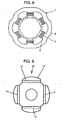
- Fig. 9 shows a top view of a rotor of the motor employed in the conventional compressor.
- Fig. 10 is a circuit diagram of the controller employed in the conventional compressor.
- stator 1 of the motor is equipped with plural teeth 5 formed on core 3. Each one of teeth 5 is wound by concentrated windings 7.
- rotor 10 of the motor forms an interior permanent magnet (IPM) rotor in which four plate-like permanent magnets 14 are buried in iron core 12.
- motor 30 comprises stator 1 shown in Fig. 8 and rotor 10 shown in Fig. 9 , and activates compressing mechanism 32 via a shaft (not shown).
- Rectifying circuit 36 for rectifying the AC of commercial power 34 adopts a voltage doubler rectifying method, so that it receives AC 100V and outputs DC250V.
- Inverter 40 is formed by bridging six pieces of switching elements for a three-phase operation. Inverter 40 converts the DC voltage output from rectifying circuit 36 into an output having a voltage and a frequency for three phases, thereby powering motor 30. Each one of the three phases is energized at 120 degrees in electric angles, so that an alternating current of rectangular waveform is supplied to motor 30.
- BEMF detecting circuit 42 detects a relative rotor position with respect to the stator by using BEMF yielded in the respective stator windings of the three phases of motor 30.
- Driver circuit 46 turns on or off the switching elements of inverter 40.
- Commutating circuit 48 determines which switching element of inverter 40 be turned on or off based on an output signal from BEMF detecting circuit 42 while motor 30 is in steady operation.
- PWM control circuit 50 chops switching elements either one of the upper arm or the lower arm of inverter 40, thereby carrying out PWM (pulse width modulation) control.
- the PWM control refers to raising/lowering of an average output voltage by raising or lowering the duty of pulse width.
- the duty is defined in this specification as a ratio of an on-period vs. a pulse cycle.
- inverter 40 compulsorily outputs a voltage having a low frequency and a low duty.
- Application of the output voltage to the stator windings compulsorily starts the motor rotating. This is generally referred to as a sync. at a low frequency for energizing.
- the motor thus starts rotating and increases its rpm to a certain level, then stator windings of respective phases yield BEMF, and BEMF detecting circuit 42 outputs a rotor position detecting signal.
- Commutating circuit 48 logically processes the position detecting signal, and outputs a commutating signal to drive circuit 46. Based on the commutating signal, drive circuit 46 turns on/off the six switching elements of inverter 40 one by one, thereby powering the respective phases of the stator windings one by one.
- the motor thus works steadily (under the feedback control by the position detecting signals) as a DC motor.
- the rpm can be detected by this signal.
- the detected rpm signal is compared with a speed reference signal, and the comparison result is fed back for adjusting the duty, thereby controlling the rpm of the motor.
- Duty on period / on period + off period ⁇ 100. For instance, when an on - period is 50 % and an off - period is 50 % , the duty becomes 50 % .
- the foregoing conventional structure controls the rpm using a pulse duty supplied from PWM control circuit 50, and a chopping frequency (hereinafter referred to as a carrier frequency) in PWM ranges from several kHz to ten and several kHz in general, so that the carrier frequency is accompanied with noises.
- a carrier frequency a chopping frequency
- IPM rotor since IPM rotor includes permanent magnets 14 therein, a magnetic path coupling iron core 12 of rotor 10 to teeth 5 of stator 1 is formed. Therefore, when a current having a rectangular waveform is supplied to stator windings 7, the magnetic path is switched to the adjacent tooth 5 at switching of powering a phase, so that magnetic force sharply changes. As a result, stator 1 is deformed, which results in generating noises. Vibration and noise can be reduced by starting the motor smoothly with a feedback control and then continue with open loop control, as proposed in documents US 2002 164255 and JP 2002325480 .
- the max. output is achieved at a duty of 100%, so that the motor cannot work at a higher rpm than the rpm at this level.
- an output of motor 30 must be increased, and in the case of using the same amount of copper as the stator windings, the motor efficiency lowers by an increased amount of output.
- three-phase sine-waveform AC instead of a rectangular waveform is applied to stator windings 7 of motor 30 so that noises can be reduced.
- a method of applying the three-phase sine-waveform AC needs a current detecting circuit for detecting a current flowing through the stator windings in order to calculate a position of the rotor, because it is difficult to obtain information about detecting a position of the rotor from the BEMF detecting circuit.
- a current transformer is used in general for detecting the current, and a high-speed microprocessor is required for calculating the rotor position.
- the method of applying the three-phase sine-waveform AC becomes expensive.
- the compressor of the present invention comprises the following elements:
- the controller works in two ways: In driving the motor at a low rpm, the controller carries out a feedback control where on/off timing of switching elements is determined by a rotor position detecting signal, and in driving the motor at a high rpm, the controller carries out an open-loop control where a signal of a given frequency is output, and the motor is synchronized with the given frequency for being driven.
- the foregoing structure allows the compressor to work at a high rpm, so that a highly efficient motor of which max. output is set at a low level is achievable. Further, a duty can be relatively greater, so that noises accompanying the carrier frequency at the PWM control can be reduced. As such, the present invention can provide a compressor of low noise and high efficiency at an inexpensive cost.
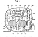
- Fig. 1 shows a sectional view of a compressor in accordance with the exemplary embodiment of the present invention.
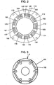
- Fig. 2 shows a top view of a stator of a motor employed in the compressor shown in Fig. 1 .
- Fig. 3 shows a top view of a rotor of a motor employed in the compressor shown in Fig. 1 .
- Fig. 4 shows a circuit diagram of a controller employed in the compressor in accordance with the exemplary embodiment of the present invention.
- Fig. 5 shows a block diagram of the controller shown in Fig. 4 .
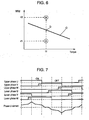
- Fig. 6 shows relations between torque and rpm of a motor employed in the compressor in accordance with the exemplary embodiment of the present invention.
- Fig. 7 shows a timing-chart illustrating on/off timing and a current waveform of switching elements of the controller employed in the compressor of the present invention.
- hermetic container 101 pools oil 103 therein and includes refrigerant 102 filled therein.
- Ideal refrigerant 102 is R600a.
- Container 101 accommodates motor 115 equipped with stator 110 and rotor 112, and also holds elastically therein compressing unit 120 to be driven by motor 115.
- Compressing unit 120 comprises the following elements:
- stator 110 has nine teeth 142 formed on core 140, and each one of teeth 142 is wound by concentrated winding 145, thereby forming a concentrated-winding stator.
- the motor is a three-phase motor including phase-U winding, phase-V winding and phase-W winding, and they are coupled to each other in the following manner:
- winding 145 represents the foregoing windings 171 - 179
- tooth 142 represents the foregoing teeth 181 - 189 for description purpose.
- rotor 112 is equipped with six plate-like permanent magnets 152 buried at iron core 150 to form a rotor of an interior permanent magnet (IPM) type.
- Permanent magnet 152 is made of, e.g. neodymium-, iron-, and boron-based rare-earth magnet.
- the motor is formed of stator 110 shown in Fig. 2 and rotor 112 disposed inside stator 110 and shown in Fig. 3 .
- An inner face of each one of teeth 142 confronts an outer face of rotor 112 via a space.
- the foregoing motor rotates using combined torque of magnet torque and reluctance torque.
- the magnet torque and the reluctance torque are produced depending on a relation between a rotary magnetic field that generated by a current flowing through winding 145 wound on each one of teeth 142 of stator 110 and permanent magnets 152 buried in iron core 150 of rotor 112.
- this motor uses not only the magnet torque but also the reluctance torque due to the effect of permanent magnets 152 buried in iron core 150 of rotor 112, so that the motor works more efficiently than other motors which use only the magnet torque.
- commercial power source 161 is, e.g. an AC power source of 100V, 60Hz.
- Controller 160 is formed of rectifying circuit 162, inverter 163, position detecting circuit 165 and control circuit 166.
- Rectifying circuit 162 rectifies the AC supplied from power source 161 and converts it into a DC.
- This embodiment employs a voltage doubler rectifying method, so that circuit 162 receives AC100V and outputs DC250V
- Inverter 163 is formed of six switching elements bridged in a three-phase manner, where the switching elements employ, e.g. insulating bipolar gate transistors (IBGT) or field effect transistors (FET). Three switching elements form an upper arm of inverter 163 and another three switching elements form a lower arm of inverter 163, and the upper elements have contacts with the lower elements respectively. Respective first ends of phase U winding, phase V winding and phase W winding are coupled to the respective contacts. Respective second ends of those windings are coupled to each other commonly and form a neutral point. Inverter 163 converts the dc output from rectifying circuit 162 into outputs having a given voltage and a given frequency for three phases by PWM control.
- IBGT insulating bipolar gate transistors
- FET field effect transistors
- inverter 163 supplies those outputs to the three-phase windings of motor 115.
- an output having an electrical angle of 120° is supplied to each one of three phases, or an output having an electrical angle ranging not less than 130° to less than 180° is supplied to one of the three phases, i.e. a wide angle energizing.
- an electrical angle of 150° is used.
- Position detecting circuit 165 detects BEMF generated at an input terminal of motor 115, i.e. the first ends of respective three-phase windings for detecting relatively a rotary position of rotor 112 with respect to stator 110.
- Control circuit 166 switches a feedback control to/from an open-loop control in response to the operation of the motor.
- the feedback control determines a timing of turning on/off the six switching elements based on an output signal from position detecting circuit 165, and the open-loop control forces inverter 163 to supply an output having a given voltage and a given frequency regardless of the output signal from circuit 165.
- Motor 115 is driven by controller 160, and rotor 112 of the motor rotates crankshaft 126.
- Eccentric movement of eccentric shaft 124 linked to the crankshaft is converted via connecting means 138 into reciprocating movement of piston 135 in compressing chamber 130, so that compressing movement can be practiced.
- controller 160 receives a signal from position detecting circuit 165, then recognizes an rpm of the motor in step 1. Next, when the rpm is found not more than a given value in step 2, i.e. driving at a low rpm, controller 160 carries out the feedback control based on the signal detecting the rotor's position in step 3. On the other hand, when the rpm is found not less than the given value in step 2, i.e. driving at a high rpm, controller 160 outputs a given frequency and synchronizes the motor with the given frequency in step 4. In other words, controller 160 carries out the open-loop control.
- This open-loop control i.e. controller 160 outputs a given frequency and synchronizes the motor with the given frequency, achieves a higher rpm than the feedback control which uses a position detecting signal.
- line C represents the characteristics of the motor at the max. duty (e.g. 100%) under the feedback control based on a position detecting signal as usual. In general, an rpm decreases at greater torque.
- control circuit 166 carries out the feedback control based on a position detecting signal, so that optimum phase-switching is practiced.
- the motor works in an efficient manner.
- control circuit 166 increases a duty in order to obtain a higher rpm aiming at point B.
- the rpm thus increases and reaches point D crossing with characteristics line C.
- the duty reaches the max. value (e.g. 100%) at point D and the rpm cannot be further increased.
- control circuit 166 fixes the duty at the max. value (e.g. 100%), and switches the control to the open-loop control which increases an output frequency.
- the max. value e.g. 100%
- the motor is synchronized with the raised frequency and driven, namely, the motor is controlled to work as a synchronous motor.
- a phase of the motor current operates in advance of a phase of BEMF generated in the stator windings, so that part of the motor current weaken the magnetic flux.
- the BEMF generated in the stator windings lowers, and the rpm for the BEMF to exceed the voltage supplied from the power source becomes higher, thereby allowing the motor to work at a higher rpm.
- This operation is generally called a field weakening control.
- Fig. 7 shows a waveform of phase U current at the bottom. Since phase V current and phase W current are displaced 120° in electrical angles respectively with respect to phase U current and take similar waveforms to that of phase U current, those waveforms are omitted from Fig. 7 .
- phase U current waveform As shown in Fig. 7 , use of 150° in electrical angles as an energizing angle for wide-angle energizing allows the phase U current waveform to lower a rising current comparing with a rectangular current waveform in the case of usual 120° energizing.
- the phase U current waveform thus approximates to a sine waveform.
- controller 160 practices the feedback control based on the position detecting signal at the low rpm driving, the current approximates to a sine waveform due to the wide angle energizing, thereby reducing torque ripples of the motor. As a result, the case in accordance with this embodiment can remarkably reduce vibrations comparing with the conventional 120° energizing.
- controller 160 practices the open-loop control at the high rpm driving, namely, driving the motor at a given frequency, and carries out the wide-angle energizing at a duty of 100%, the current approximates to a sine waveform, thereby reducing the torque ripples of the motor. As a result, the motor spins smoothly, and the higher rpm can be expected.
- the electrical angle of 150° is used as an energizing angle; however, an angle ranging from not less than 130° to less than 180° can produce a similar advantage to what is discussed above, and a case using one of those angles still falls within the scope of the present invention.
- the compressor in accordance with this exemplary embodiment needs the same refrigerating capacity as a conventional one, the compressor can reduce its cylinder volume due to the advantage of this embodiment.
- piston 135 shown in Fig. 1 can be downsized, or an eccentric amount of eccentric shaft 124 with respect to main shaft 123 can be reduced.
- the compressor in accordance with this embodiment can reduce vibrations at compressing unit 120.
- This advantage can be revealed explicitly when R600a is used as refrigerant because R600a has a small refrigerant capacity but needs a large cylinder volume.
- the advantage of this embodiment allows a user to use a motor of which max. output is set at a low level, so that a motor having windings more tightly wound, i.e. a highly efficient motor, can be employed, which can form an efficient compressor.
- the duty at the same rpm can be relatively increased, so that noises at the carrier frequency under the PWM control can be relatively lowered.
- a stator is formed by providing each one of the teeth of the iron core with a concentrated winding, and this stator can reduce noises of the carrier frequency and the torque ripples although it has a little vibration attenuating effect between the windings and the teeth, and tends to produce sounds by being vibrated.
- the compressor of the present invention thus achieves a low noise operation using an inexpensive and yet efficient motor with the concentrated windings.
- the motor of the compressor in accordance with the present invention includes permanent magnets 152 shaped like plates and buried in iron core 150 of rotor 112 to form the IPM rotor which uses both of magnet torque and reluctance torque for the motor to work efficiently. Further, permanent magnets 152 are formed of neodymium-, iron-, and boron-based rare earth magnet in order to increase the magnetic flux density for obtaining higher efficiency.
- the interior magnets couple the iron core of the rotor to the teeth of the stator, thereby forming a powerful magnetic path.
- permanent magnets 152 are made of rare-earth magnet, a more powerful magnetic path can be formed.
- the magnetic path changes to an adjacent tooth at a phase switch, so that magnetic force sharply changes, which deforms the stator, thereby generating noises.
- the phase current is similar to a sine waveform
- the current value becomes smaller before and after the phase switch, and even after the phase switch, the current value increases or decreases smoothly, so that magnetic forth changes only a little with respect to the stator.
- the deformation of the stator is suppressed, and vibrations are also suppressed to a low level, thereby achieving an efficient and low-noise compressor.
- this exemplary embodiment proves that the present invention achieves an inexpensive, low-noise, and efficient compressor.
- a reciprocating compressor elastically supported in a hermetic container is demonstrated; however, a stator can be directly fixed to a hermetic container with a similar advantage, and a rotary compressor or a scrolling compressor also produces a similar advantage to what is discussed above.
- the permanent magnet made of rare-earth magnet is used; however, a magnet made of ferrite magnet can be used with a similar operation and advantage.
- rectifying circuit 162 adopts a voltage doubler rectifying method; however, it can adopt another rectifying method, e.g. a full-wave rectifying circuit or a half-wave rectifying circuit. It can also adopt a method that can switch an output voltage (e.g. voltage doubler rectification and full-wave rectification are switched by a relay or a semiconductor switch) or a method that can change an output to a linear one (e.g. DC-DC converter such as boosting chopper or high-voltage chopper).
- Position detecting circuit 165 adopts a method of detecting BEMF generated at an input terminal of motor 115; however, it can use a position detecting sensor such as a Hall element instead.
- the controller of the motor used in the compressor of the present invention practices the feedback control which drives the motor in PWM manner based on a position detecting signal at the low rpm driving.
- the controller practices the open-loop control which outputs a given frequency at the high rpm driving.
- the controller raises the output frequency regardless of the position detecting signal, and the rpm is raised synchronously with the frequency, so that the motor works as a synchronous motor.
- a current phase of the motor thus operates in advance of a phase of BEMF of the motor, then the field weakening control is activated, thereby allowing the motor to work at a higher rpm.
- an efficient motor of which max. output is set at a lower level can be used, and a duty for obtaining the same rpm can be relatively increased, thereby reducing noises of a carrier frequency under PWM control.
- the compressor of the present invention can work at a high rpm, so that it can employ an efficient motor of which maximum output is set at a lower level.
- a duty can be relatively increased from a conventional one, thereby reducing noises of a carrier frequency under PWM control.
- This compressor is suitable for household refrigerators and air-conditioners.
Landscapes
- Engineering & Computer Science (AREA)
- Mechanical Engineering (AREA)
- General Engineering & Computer Science (AREA)
- Power Engineering (AREA)
- Control Of Motors That Do Not Use Commutators (AREA)
- Compressor (AREA)
Description
- The present invention relates to electric compressors driven by an inverter and used mainly in household refrigerators and air-conditioners.
- Recently a brush-less DC motor has been increasingly employed in compressors used in refrigerating systems because of its high efficiency. A conventional compressor is known to work in the following manner: Detect a rotor position using back electromotive force (BEMF) yielded in stator windings of a motor, and drive the motor based on the detection signal, at the same time, chop the switching elements, thereby practicing the pulse width modulation control. An instance of such a conventional compressor is disclosed in Japanese Patent Application Non-Examined Publication No.
H03 - 55478 - A controller of the conventional compressor is described hereinafter with reference to
Fig. 8 - Fig. 10 .Fig. 8 shows a top view of a stator of a motor employed in the conventional compressor.Fig. 9 shows a top view of a rotor of the motor employed in the conventional compressor.Fig. 10 is a circuit diagram of the controller employed in the conventional compressor. - In
Fig. 8 ,stator 1 of the motor is equipped withplural teeth 5 formed oncore 3. Each one ofteeth 5 is wound byconcentrated windings 7. InFig. 9 ,rotor 10 of the motor forms an interior permanent magnet (IPM) rotor in which four plate-likepermanent magnets 14 are buried iniron core 12. InFig. 10 ,motor 30 comprisesstator 1 shown inFig. 8 androtor 10 shown inFig. 9 , and activatescompressing mechanism 32 via a shaft (not shown). Rectifyingcircuit 36 for rectifying the AC ofcommercial power 34 adopts a voltage doubler rectifying method, so that it receives AC 100V and outputs DC250V. -
Inverter 40 is formed by bridging six pieces of switching elements for a three-phase operation.Inverter 40 converts the DC voltage output from rectifyingcircuit 36 into an output having a voltage and a frequency for three phases, thereby poweringmotor 30. Each one of the three phases is energized at 120 degrees in electric angles, so that an alternating current of rectangular waveform is supplied tomotor 30. - Back electromotive force (BEMF) detecting
circuit 42 detects a relative rotor position with respect to the stator by using BEMF yielded in the respective stator windings of the three phases ofmotor 30.Driver circuit 46 turns on or off the switching elements ofinverter 40. Commutatingcircuit 48 determines which switching element ofinverter 40 be turned on or off based on an output signal fromBEMF detecting circuit 42 whilemotor 30 is in steady operation.PWM control circuit 50 chops switching elements either one of the upper arm or the lower arm ofinverter 40, thereby carrying out PWM (pulse width modulation) control. - The PWM control refers to raising/lowering of an average output voltage by raising or lowering the duty of pulse width. The duty is defined in this specification as a ratio of an on-period vs. a pulse cycle.
- An operation of the controller of the conventional compressor discussed above is described hereinafter. When
motor 30 is activated from a stopped state, it is impossible to detect a rotor position because the rotor windings do not yield BEMF yet. Thus inverter 40 compulsorily outputs a voltage having a low frequency and a low duty. Application of the output voltage to the stator windings compulsorily starts the motor rotating. This is generally referred to as a sync. at a low frequency for energizing. - The motor thus starts rotating and increases its rpm to a certain level, then stator windings of respective phases yield BEMF, and
BEMF detecting circuit 42 outputs a rotor position detecting signal. Commutatingcircuit 48 logically processes the position detecting signal, and outputs a commutating signal to drivecircuit 46. Based on the commutating signal,drive circuit 46 turns on/off the six switching elements ofinverter 40 one by one, thereby powering the respective phases of the stator windings one by one. The motor thus works steadily (under the feedback control by the position detecting signals) as a DC motor. - With respect to the DC motor, variation of a voltage applied to the motor can control rpm. Therefore, increment of duty in PWM based on a signal supplied from
PWM control circuit 50 raises an average of the voltages applied to the motor, so that the motor increases its rpm. On the contrary, decrement of the duty lowers the average of the voltages applied to the motor, so that the motor reduces its rpm. - Since the position detecting signal supplied from
BEMF detecting circuit 42 synchronizes with the rotation of the rotor, the rpm can be detected by this signal. The detected rpm signal is compared with a speed reference signal, and the comparison result is fed back for adjusting the duty, thereby controlling the rpm of the motor. - Meanwhile, the duty is defined by the following equation:

- The foregoing conventional structure controls the rpm using a pulse duty supplied from
PWM control circuit 50, and a chopping frequency (hereinafter referred to as a carrier frequency) in PWM ranges from several kHz to ten and several kHz in general, so that the carrier frequency is accompanied with noises. - Since IPM rotor includes
permanent magnets 14 therein, a magnetic pathcoupling iron core 12 ofrotor 10 toteeth 5 ofstator 1 is formed. Therefore, when a current having a rectangular waveform is supplied tostator windings 7, the magnetic path is switched to theadjacent tooth 5 at switching of powering a phase, so that magnetic force sharply changes. As a result,stator 1 is deformed, which results in generating noises. Vibration and noise can be reduced by starting the motor smoothly with a feedback control and then continue with open loop control, as proposed in documentsUS 2002 164255 andJP 2002325480 - Since the rpm is controlled by a pulse duty, the max. output is achieved at a duty of 100%, so that the motor cannot work at a higher rpm than the rpm at this level. In order to obtain a necessary capacity of the compressor, an output of
motor 30 must be increased, and in the case of using the same amount of copper as the stator windings, the motor efficiency lowers by an increased amount of output. - In order to solve the problems discussed above, three-phase sine-waveform AC instead of a rectangular waveform is applied to
stator windings 7 ofmotor 30 so that noises can be reduced. However, a method of applying the three-phase sine-waveform AC needs a current detecting circuit for detecting a current flowing through the stator windings in order to calculate a position of the rotor, because it is difficult to obtain information about detecting a position of the rotor from the BEMF detecting circuit. In such a case, a current transformer is used in general for detecting the current, and a high-speed microprocessor is required for calculating the rotor position. As a result, the method of applying the three-phase sine-waveform AC becomes expensive. - The compressor of the present invention comprises the following elements:
- a hermetic container in which refrigerant is filled;
- a motor having a stator and a rotor equipped with permanent magnets, and being accommodated in the hermetic container and driven by a controller; and
- a compressing unit accommodated in the hermetic container and driven by the motor.
- The controller works in two ways: In driving the motor at a low rpm, the controller carries out a feedback control where on/off timing of switching elements is determined by a rotor position detecting signal, and in driving the motor at a high rpm, the controller carries out an open-loop control where a signal of a given frequency is output, and the motor is synchronized with the given frequency for being driven.
- The foregoing structure allows the compressor to work at a high rpm, so that a highly efficient motor of which max. output is set at a low level is achievable. Further, a duty can be relatively greater, so that noises accompanying the carrier frequency at the PWM control can be reduced. As such, the present invention can provide a compressor of low noise and high efficiency at an inexpensive cost.
-
-
Fig. 1 shows a sectional view of a compressor in accordance with an exemplary embodiment of the present invention. -
Fig. 2 shows a top view of a stator of a motor employed in the compressor shown inFig. 1 . -
Fig. 3 shows a top view of a rotor of a motor employed in the compressor shown inFig. 1 . -
Fig. 4 shows a circuit diagram of a controller employed in a compressor in accordance with an exemplary embodiment of the present invention. -
Fig. 5 shows a block diagram of the controller shown inFig. 4 . -
Fig. 6 shows relations between torque and rpm of a motor employed in a compressor in accordance with an exemplary embodiment of the present invention. -
Fig. 7 shows characteristics of the controller employed in a compressor in accordance with an exemplary embodiment of the present invention. -
Fig. 8 shows a top view of a stator of a motor employed in a conventional compressor. -
Fig. 9 shows a top view of a rotor of a motor employed in the conventional compressor. -
Fig. 10 shows a circuit diagram of a controller employed in the conventional compressor. - An exemplary embodiment of the present invention is demonstrated hereinafter with reference to the accompanying drawings.
-
Fig. 1 shows a sectional view of a compressor in accordance with the exemplary embodiment of the present invention.Fig. 2 shows a top view of a stator of a motor employed in the compressor shown inFig. 1 .Fig. 3 shows a top view of a rotor of a motor employed in the compressor shown inFig. 1 .Fig. 4 shows a circuit diagram of a controller employed in the compressor in accordance with the exemplary embodiment of the present invention.Fig. 5 shows a block diagram of the controller shown inFig. 4 .Fig. 6 shows relations between torque and rpm of a motor employed in the compressor in accordance with the exemplary embodiment of the present invention.Fig. 7 shows a timing-chart illustrating on/off timing and a current waveform of switching elements of the controller employed in the compressor of the present invention. - In
Fig. 1 ,hermetic container 101pools oil 103 therein and includes refrigerant 102 filled therein.Ideal refrigerant 102 is R600a.Container 101 accommodatesmotor 115 equipped withstator 110 androtor 112, and also holds elastically therein compressingunit 120 to be driven bymotor 115. - Compressing
unit 120 comprises the following elements: -
crankshaft 126 formed ofmain shaft 123, to whichrotor 112 is fixed, andeccentric shaft 124; -
cylinder 132 for rotatably supportingmain shaft 123 and including compressingchamber 130; -
piston 135 for reciprocating within compressingchamber 130; and - connecting means 138 for coupling
eccentric shaft 124 topiston 135. - As shown in
Fig. 2 ,stator 110 has nineteeth 142 formed oncore 140, and each one ofteeth 142 is wound by concentrated winding 145, thereby forming a concentrated-winding stator. - The motor is a three-phase motor including phase-U winding, phase-V winding and phase-W winding, and they are coupled to each other in the following manner:
- Winding 171 is concentratively wound on
tooth 181. Winding 174 is concentratively wound ontooth 184. Winding 177 is concentratively wound ontooth 187. Thosewindings - Winding 172 is concentratively wound on
tooth 182. Winding 175 is concentratively wound ontooth 185. Winding 178 is concentratively wound ontooth 188. Thosewindings - Winding 173 is concentratively wound on
tooth 183. Winding 176 is concentratively wound ontooth 186. Winding 179 is concentratively wound ontooth 189. Thosewindings - In this embodiment, winding 145 represents the foregoing windings 171 - 179, and
tooth 142 represents the foregoing teeth 181 - 189 for description purpose. - In
Fig. 3 ,rotor 112 is equipped with six plate-likepermanent magnets 152 buried atiron core 150 to form a rotor of an interior permanent magnet (IPM) type.Permanent magnet 152 is made of, e.g. neodymium-, iron-, and boron-based rare-earth magnet. - The motor is formed of
stator 110 shown inFig. 2 androtor 112 disposed insidestator 110 and shown inFig. 3 . An inner face of each one ofteeth 142 confronts an outer face ofrotor 112 via a space. - The foregoing motor rotates using combined torque of magnet torque and reluctance torque. The magnet torque and the reluctance torque are produced depending on a relation between a rotary magnetic field that generated by a current flowing through winding 145 wound on each one of
teeth 142 ofstator 110 andpermanent magnets 152 buried iniron core 150 ofrotor 112. In other words, this motor uses not only the magnet torque but also the reluctance torque due to the effect ofpermanent magnets 152 buried iniron core 150 ofrotor 112, so that the motor works more efficiently than other motors which use only the magnet torque. - Next, the controller of the compressor in accordance with this exemplary embodiment is demonstrated hereinafter. In
Fig. 4 ,commercial power source 161 is, e.g. an AC power source of 100V, 60Hz.Controller 160 is formed of rectifyingcircuit 162,inverter 163,position detecting circuit 165 andcontrol circuit 166. - Rectifying
circuit 162 rectifies the AC supplied frompower source 161 and converts it into a DC. This embodiment employs a voltage doubler rectifying method, so thatcircuit 162 receives AC100V and outputs DC250V -
Inverter 163 is formed of six switching elements bridged in a three-phase manner, where the switching elements employ, e.g. insulating bipolar gate transistors (IBGT) or field effect transistors (FET). Three switching elements form an upper arm ofinverter 163 and another three switching elements form a lower arm ofinverter 163, and the upper elements have contacts with the lower elements respectively. Respective first ends of phase U winding, phase V winding and phase W winding are coupled to the respective contacts. Respective second ends of those windings are coupled to each other commonly and form a neutral point.Inverter 163 converts the dc output from rectifyingcircuit 162 into outputs having a given voltage and a given frequency for three phases by PWM control. Theninverter 163 supplies those outputs to the three-phase windings ofmotor 115. In this case, an output having an electrical angle of 120° is supplied to each one of three phases, or an output having an electrical angle ranging not less than 130° to less than 180° is supplied to one of the three phases, i.e. a wide angle energizing. In this embodiment, an electrical angle of 150° is used. -
Position detecting circuit 165 detects BEMF generated at an input terminal ofmotor 115, i.e. the first ends of respective three-phase windings for detecting relatively a rotary position ofrotor 112 with respect tostator 110. -
Control circuit 166 switches a feedback control to/from an open-loop control in response to the operation of the motor. The feedback control determines a timing of turning on/off the six switching elements based on an output signal fromposition detecting circuit 165, and the open-loop control forces inverter 163 to supply an output having a given voltage and a given frequency regardless of the output signal fromcircuit 165. - An operation of the foregoing compressor is this:
Motor 115 is driven bycontroller 160, androtor 112 of the motor rotatescrankshaft 126. Eccentric movement ofeccentric shaft 124 linked to the crankshaft is converted via connectingmeans 138 into reciprocating movement ofpiston 135 in compressingchamber 130, so that compressing movement can be practiced. - An operation of
controller 160 is demonstrated with reference toFig. 5 . InFig. 5 ,controller 160 receives a signal fromposition detecting circuit 165, then recognizes an rpm of the motor instep 1. Next, when the rpm is found not more than a given value in step 2, i.e. driving at a low rpm,controller 160 carries out the feedback control based on the signal detecting the rotor's position instep 3. On the other hand, when the rpm is found not less than the given value in step 2, i.e. driving at a high rpm,controller 160 outputs a given frequency and synchronizes the motor with the given frequency in step 4. In other words,controller 160 carries out the open-loop control. - This open-loop control, i.e.
controller 160 outputs a given frequency and synchronizes the motor with the given frequency, achieves a higher rpm than the feedback control which uses a position detecting signal. - The operations by the feedback control and the open-loop control are further detailed with reference to
Fig. 6 . InFig. 6 , line C represents the characteristics of the motor at the max. duty (e.g. 100%) under the feedback control based on a position detecting signal as usual. In general, an rpm decreases at greater torque. - Assume that an instructed rpm of the motor is "r1" and torque is "t1", in this condition the motor works at point A. At this time,
control circuit 166 carries out the feedback control based on a position detecting signal, so that optimum phase-switching is practiced. Thus the motor works in an efficient manner. - Assume that the instructed rpm is changed to r2, then control
circuit 166 increases a duty in order to obtain a higher rpm aiming at point B. The rpm thus increases and reaches point D crossing with characteristics line C. The duty reaches the max. value (e.g. 100%) at point D and the rpm cannot be further increased. - At this time,
control circuit 166 fixes the duty at the max. value (e.g. 100%), and switches the control to the open-loop control which increases an output frequency. In other words, only the output frequency is raised regardless of the position detecting signal, and the motor is synchronized with the raised frequency and driven, namely, the motor is controlled to work as a synchronous motor. - In this case, a phase of the motor current operates in advance of a phase of BEMF generated in the stator windings, so that part of the motor current weaken the magnetic flux. As a result, the BEMF generated in the stator windings lowers, and the rpm for the BEMF to exceed the voltage supplied from the power source becomes higher, thereby allowing the motor to work at a higher rpm. This operation is generally called a field weakening control.
- Next, energizing by use of a wider angle driving-waveform is described with reference to
Fig. 7 . InFig. 7 , the lateral axis represents time, and the vertical axis represents on/off status of each one of switching elements, i.e. an element at upper phase U, upper phase V, upper phase W, lower phase U, lower phase V, and lower phase W.Fig. 7 also shows a waveform of phase U current at the bottom. Since phase V current and phase W current are displaced 120° in electrical angles respectively with respect to phase U current and take similar waveforms to that of phase U current, those waveforms are omitted fromFig. 7 . - As shown in
Fig. 7 , use of 150° in electrical angles as an energizing angle for wide-angle energizing allows the phase U current waveform to lower a rising current comparing with a rectangular current waveform in the case of usual 120° energizing. The phase U current waveform thus approximates to a sine waveform. - When
controller 160 practices the feedback control based on the position detecting signal at the low rpm driving, the current approximates to a sine waveform due to the wide angle energizing, thereby reducing torque ripples of the motor. As a result, the case in accordance with this embodiment can remarkably reduce vibrations comparing with the conventional 120° energizing. - When
controller 160 practices the open-loop control at the high rpm driving, namely, driving the motor at a given frequency, and carries out the wide-angle energizing at a duty of 100%, the current approximates to a sine waveform, thereby reducing the torque ripples of the motor. As a result, the motor spins smoothly, and the higher rpm can be expected. - In the foregoing discussion, the electrical angle of 150° is used as an energizing angle; however, an angle ranging from not less than 130° to less than 180° can produce a similar advantage to what is discussed above, and a case using one of those angles still falls within the scope of the present invention.
- If the compressor in accordance with this exemplary embodiment needs the same refrigerating capacity as a conventional one, the compressor can reduce its cylinder volume due to the advantage of this embodiment. Thus
piston 135 shown inFig. 1 can be downsized, or an eccentric amount ofeccentric shaft 124 with respect tomain shaft 123 can be reduced. As a result, the compressor in accordance with this embodiment can reduce vibrations at compressingunit 120. This advantage can be revealed explicitly when R600a is used as refrigerant because R600a has a small refrigerant capacity but needs a large cylinder volume. - The advantage of this embodiment allows a user to use a motor of which max. output is set at a low level, so that a motor having windings more tightly wound, i.e. a highly efficient motor, can be employed, which can form an efficient compressor.
- The duty at the same rpm can be relatively increased, so that noises at the carrier frequency under the PWM control can be relatively lowered.
- A stator is formed by providing each one of the teeth of the iron core with a concentrated winding, and this stator can reduce noises of the carrier frequency and the torque ripples although it has a little vibration attenuating effect between the windings and the teeth, and tends to produce sounds by being vibrated. The compressor of the present invention thus achieves a low noise operation using an inexpensive and yet efficient motor with the concentrated windings.
- The motor of the compressor in accordance with the present invention includes
permanent magnets 152 shaped like plates and buried iniron core 150 ofrotor 112 to form the IPM rotor which uses both of magnet torque and reluctance torque for the motor to work efficiently. Further,permanent magnets 152 are formed of neodymium-, iron-, and boron-based rare earth magnet in order to increase the magnetic flux density for obtaining higher efficiency. - In the IPM rotor, the interior magnets couple the iron core of the rotor to the teeth of the stator, thereby forming a powerful magnetic path. In this embodiment, since
permanent magnets 152 are made of rare-earth magnet, a more powerful magnetic path can be formed. As a result, when each phase current shows a rectangular waveform, the magnetic path changes to an adjacent tooth at a phase switch, so that magnetic force sharply changes, which deforms the stator, thereby generating noises. - However, according to this embodiment, since the phase current is similar to a sine waveform, the current value becomes smaller before and after the phase switch, and even after the phase switch, the current value increases or decreases smoothly, so that magnetic forth changes only a little with respect to the stator. As a result, the deformation of the stator is suppressed, and vibrations are also suppressed to a low level, thereby achieving an efficient and low-noise compressor.
- As discussed above, this exemplary embodiment proves that the present invention achieves an inexpensive, low-noise, and efficient compressor.
- In this embodiment, a reciprocating compressor elastically supported in a hermetic container is demonstrated; however, a stator can be directly fixed to a hermetic container with a similar advantage, and a rotary compressor or a scrolling compressor also produces a similar advantage to what is discussed above.
- In this embodiment, the permanent magnet made of rare-earth magnet is used; however, a magnet made of ferrite magnet can be used with a similar operation and advantage.
- Further in this embodiment, rectifying
circuit 162 adopts a voltage doubler rectifying method; however, it can adopt another rectifying method, e.g. a full-wave rectifying circuit or a half-wave rectifying circuit. It can also adopt a method that can switch an output voltage (e.g. voltage doubler rectification and full-wave rectification are switched by a relay or a semiconductor switch) or a method that can change an output to a linear one (e.g. DC-DC converter such as boosting chopper or high-voltage chopper).Position detecting circuit 165 adopts a method of detecting BEMF generated at an input terminal ofmotor 115; however, it can use a position detecting sensor such as a Hall element instead. - As discussed above, the controller of the motor used in the compressor of the present invention practices the feedback control which drives the motor in PWM manner based on a position detecting signal at the low rpm driving. The controller, on the other hand, practices the open-loop control which outputs a given frequency at the high rpm driving. When the motor is driven at a high rpm, the controller raises the output frequency regardless of the position detecting signal, and the rpm is raised synchronously with the frequency, so that the motor works as a synchronous motor. A current phase of the motor thus operates in advance of a phase of BEMF of the motor, then the field weakening control is activated, thereby allowing the motor to work at a higher rpm. As a result, an efficient motor of which max. output is set at a lower level can be used, and a duty for obtaining the same rpm can be relatively increased, thereby reducing noises of a carrier frequency under PWM control.
- The compressor of the present invention can work at a high rpm, so that it can employ an efficient motor of which maximum output is set at a lower level. A duty can be relatively increased from a conventional one, thereby reducing noises of a carrier frequency under PWM control. As a result, an inexpensive, low-noise, and efficient compressor can be achieved. This compressor is suitable for household refrigerators and air-conditioners.
-
- 101
- Hermetic container
- 102
- Refrigerant
- 110
- Stator
- 112
- Rotor
- 115
- Motor
- 120
- Compressing unit
- 123
- Main shaft
- 124
- Eccentric shaft
- 126
- Crankshaft
- 130
- Compressing chamber
- 132
- Cylinder
- 135
- Piston
- 138
- Connecting means
- 140
- Core
- 142
- Teeth
- 145
- Winding
- 150
- Iron core
- 152
- Permanent magnet
- 160
- Controller
Claims (6)
- An electric compressor comprising:a hermetic container (101) in which refrigerant (102) is filled;a motor (115) having a stator (110) and a rotor (112) equipped with a permanent magnet (152), and being accommodated in the hermetic container and driven by a controller (160);a position detecting device (165) for detecting a position of the rotor and outputting a rotor position detection signal; anda compressing unit (120) accommodated in the hermetic container and driven by the motor,wherein when the motor is driven at a rpm not above a predetermined value, the controller practices a feedback control which determines a timing of turning on/off switching elements based on the rotor position detection signal, and when the motor is driven at a rpm not below said predetermined value, the controller practices an open-loop control which outputs a given frequency and drives the motor synchronizing with the given frequency independently of the rotor position detection signal so as to achieve a higher rpm than the feedback control, wherein the rpm is raised synchronously with the output frequency.
- The compressor of claim 1, wherein the motor (115) is a three-phase motor, and the controller (160) energizes each one of the three phases of the motor at an electric angle ranging from not less than 130° to less than 180°.
- The compressor of claim 1 or claim 2, wherein the stator (110) includes teeth (142) wound by windings (145) in a concentrated manner.
- The compressor of claim 1 or claim 2, wherein the permanent magnet (152) is buried in an iron core (150) which forms the rotor (112).
- The compressor of claim 1 or claim 2, wherein the compressing unit (120) includes a cylinder (132) forming a compressing chamber (130), a piston (135) reciprocating in the compressing chamber, a crankshaft (126) having a main shaft (123) and an eccentric shaft (124), and a connecting means (138) coupling the piston to the eccentric shaft.
- The compressor of claim 1 or claim 2, wherein the refrigerant (102) is R600a.
Applications Claiming Priority (7)
| Application Number | Priority Date | Filing Date | Title |
|---|---|---|---|
| JP2003071421A JP4341266B2 (en) | 2003-03-17 | 2003-03-17 | Method and apparatus for driving brushless DC motor |
| JP2003071421 | 2003-03-17 | ||
| JP2003327817A JP2005094971A (en) | 2003-09-19 | 2003-09-19 | Method and apparatus for driving brushless DC motor |
| JP2003327817 | 2003-09-19 | ||
| JP2003417810 | 2003-12-16 | ||
| JP2003417810A JP4300991B2 (en) | 2003-12-16 | 2003-12-16 | Brushless DC motor drive device |
| PCT/JP2004/003464 WO2004084401A1 (en) | 2003-03-17 | 2004-03-16 | Electrically powered compressor |
Publications (3)
| Publication Number | Publication Date |
|---|---|
| EP1505718A1 EP1505718A1 (en) | 2005-02-09 |
| EP1505718A4 EP1505718A4 (en) | 2013-04-10 |
| EP1505718B1 true EP1505718B1 (en) | 2014-08-13 |
Family
ID=33033071
Family Applications (1)
| Application Number | Title | Priority Date | Filing Date |
|---|---|---|---|
| EP04720995.2A Expired - Lifetime EP1505718B1 (en) | 2003-03-17 | 2004-03-16 | Electrically powered compressor |
Country Status (5)
| Country | Link |
|---|---|
| US (2) | US7102306B2 (en) |
| EP (1) | EP1505718B1 (en) |
| KR (2) | KR100702913B1 (en) |
| TW (1) | TW200507435A (en) |
| WO (2) | WO2004084400A1 (en) |
Families Citing this family (52)
| Publication number | Priority date | Publication date | Assignee | Title |
|---|---|---|---|---|
| JP2003507006A (en) | 1999-05-20 | 2003-02-25 | サイオス,インコーポレーテッド | Vascular endothelial growth factor variant |
| WO2004084400A1 (en) * | 2003-03-17 | 2004-09-30 | Matsushita Electric Industrial Co., Ltd. | Method of driving brushless dc motor and device therefor |
| JP2006042446A (en) * | 2004-07-23 | 2006-02-09 | Yamaha Motor Co Ltd | Abnormality monitoring device for motor control system |
| KR20070074623A (en) * | 2004-10-29 | 2007-07-12 | 캐리어 코포레이션 | GBS control |
| WO2006057418A1 (en) * | 2004-11-24 | 2006-06-01 | Matsushita Electric Industrial Co., Ltd. | Hermetic compressor |
| DE102005028344A1 (en) * | 2005-02-05 | 2006-08-17 | Diehl Ako Stiftung & Co. Kg | Method and circuit arrangement for controlling a multiphase brushless electric motor |
| DE102005013773A1 (en) * | 2005-03-22 | 2006-09-28 | Diehl Ako Stiftung & Co. Kg | Electronic motor regulation for pump used in e.g. dishwasher, involves detecting and estimating rotor phase position and rotor speed of motor and determining fluctuations in rotor phase position and rotor speed to control pump operation |
| KR101234825B1 (en) * | 2005-05-13 | 2013-02-20 | 삼성전자주식회사 | Apparatus and method for controlling linear compressor |
| JP4878127B2 (en) * | 2005-06-10 | 2012-02-15 | 株式会社トプコン | Time difference measuring device, distance measuring device, and distance measuring method |
| JP5010836B2 (en) * | 2006-02-27 | 2012-08-29 | 日立オートモティブシステムズ株式会社 | Motor drive device, motor drive method, and electric brake device |
| US7955455B2 (en) * | 2006-06-14 | 2011-06-07 | Marketing Technology Service, Inc. | Wave-like structures bonded to flat surfaces in unitized composites and methods for making same |
| WO2008017211A1 (en) | 2006-08-04 | 2008-02-14 | Jun Liu | A surface motor direct-drive sucker-rod screw pump device |
| JP2008138526A (en) * | 2006-11-30 | 2008-06-19 | Daikin Ind Ltd | Compressor |
| JP4469886B2 (en) * | 2007-09-20 | 2010-06-02 | 日立オートモティブシステムズ株式会社 | Load drive circuit |
| KR101561922B1 (en) * | 2007-12-21 | 2015-10-20 | 엘지전자 주식회사 | Motor control method of air conditioner |
| EP2110921B1 (en) | 2008-04-14 | 2013-06-19 | Stanley Black & Decker, Inc. | Battery management system for a cordless tool |
| KR101244588B1 (en) * | 2008-04-28 | 2013-04-01 | 다이킨 고교 가부시키가이샤 | Inverter control device and power conversion device |
| KR100984251B1 (en) * | 2008-06-27 | 2010-09-30 | 전남대학교산학협력단 | LLCD Motor Control Device Using Maximum Output Algorithm |
| JP5428745B2 (en) * | 2008-12-02 | 2014-02-26 | パナソニック株式会社 | Motor drive device, compressor and refrigerator |
| JP5195444B2 (en) * | 2009-01-14 | 2013-05-08 | パナソニック株式会社 | Brushless DC motor driving apparatus, refrigerator and air conditioner using the same |
| BRPI1006833B1 (en) * | 2009-01-14 | 2020-10-20 | Panasonic Corporation | motor drive device |
| JP5515384B2 (en) * | 2009-04-15 | 2014-06-11 | アイシン精機株式会社 | AC motor control device and control method |
| US9071188B2 (en) * | 2009-09-04 | 2015-06-30 | Black & Decker Inc. | Protective redundant subsystem for power tools |
| WO2011054074A1 (en) * | 2009-11-06 | 2011-05-12 | Bosch Security Systems Bv | Brushless motor speed control system |
| DE102011009563A1 (en) * | 2010-01-30 | 2011-08-04 | ebm-papst St. Georgen GmbH & Co. KG, 78112 | Method for improving the efficiency of a multiphase motor, and motor for carrying out such a method |
| US8266743B2 (en) | 2010-08-23 | 2012-09-18 | Midmark Corporation | Examination table with motion tracking |
| JP5445426B2 (en) | 2010-10-27 | 2014-03-19 | 株式会社豊田自動織機 | Electric motor control device for electric compressor |
| JP2012130980A (en) | 2010-12-21 | 2012-07-12 | Makita Corp | Cordless electric power tool |
| JP5798134B2 (en) | 2011-02-10 | 2015-10-21 | 株式会社マキタ | Electric tool |
| JP2013034364A (en) * | 2011-06-29 | 2013-02-14 | Panasonic Corp | Inverter control device, electric compressor using the same and electrical equipment |
| CN102437805B (en) * | 2011-09-15 | 2013-11-13 | 威海克莱特机电有限公司 | Compensation calculation method of heavy load phase of brushless direct current (DC) motor without position sensor |
| CN104066991B (en) * | 2012-03-02 | 2016-03-30 | 松下电器产业株式会社 | The controlling method of motor compressor, control gear and refrigerated warehouse |
| KR102270420B1 (en) * | 2013-08-28 | 2021-06-29 | 엘지이노텍 주식회사 | Motor, method and apparatus for operating the motor |
| US9893384B2 (en) | 2014-05-18 | 2018-02-13 | Black & Decker Inc. | Transport system for convertible battery pack |
| JP6737709B2 (en) | 2014-05-18 | 2020-08-12 | ブラック アンド デッカー インクBlack & Decker Inc. | Power tool system |
| WO2016100884A1 (en) | 2014-12-18 | 2016-06-23 | Black & Decker Inc. | Control scheme to increase tool usage as battery drains |
| KR102202419B1 (en) * | 2015-04-17 | 2021-01-13 | 한온시스템 주식회사 | Motor driven compressor |
| GB201513549D0 (en) * | 2015-07-31 | 2015-09-16 | Siemens Ag | Inverter |
| US10281185B2 (en) * | 2015-08-28 | 2019-05-07 | Mitsubishi Electric Corporation | Motor driving device, and heat pump device and refrigerating and air conditioning device using the motor driving device |
| WO2017079295A1 (en) | 2015-11-02 | 2017-05-11 | Black & Decker Inc. | Reducing noise and lowering harmonics in power tools using conduction band control schemes |
| CN105840455A (en) * | 2016-06-12 | 2016-08-10 | 东莞瑞柯电子科技股份有限公司 | A high-efficiency air pump |
| JP6937471B2 (en) * | 2016-07-27 | 2021-09-22 | パナソニックIpマネジメント株式会社 | Brushless DC motor |
| JP2018046628A (en) * | 2016-09-13 | 2018-03-22 | 株式会社東芝 | Brushless DC motor control device and brushless DC motor device |
| WO2018119256A1 (en) | 2016-12-23 | 2018-06-28 | Black & Decker Inc. | Cordless power tool system |
| US10439525B2 (en) * | 2017-06-05 | 2019-10-08 | Canon Kabushiki Kaisha | Motor drive device and method for driving motor |
| CN109873578B (en) * | 2017-12-04 | 2023-03-24 | 南京泉峰科技有限公司 | Electric tool and control method thereof |
| DE102018209710A1 (en) * | 2018-06-15 | 2019-12-19 | Robert Bosch Gmbh | Method for operating an electrical machine, control device and electrical machine |
| EP3806273A1 (en) | 2019-10-11 | 2021-04-14 | Black & Decker Inc. | Power tool receiving different capacity batttery packs |
| US11626822B2 (en) | 2019-10-28 | 2023-04-11 | Hale Products, Inc. | Low-speed high torque motor control and foam system |
| WO2021140846A1 (en) * | 2020-01-08 | 2021-07-15 | 株式会社山田製作所 | Electric pump and failure state notification method for electric pump |
| US12138500B2 (en) | 2020-06-19 | 2024-11-12 | Hale Products, Inc. | Fire truck valve checker system and method |
| TWI829157B (en) * | 2022-05-11 | 2024-01-11 | 茂達電子股份有限公司 | Motor controller circuit having rotational speed locking mechanism |
Family Cites Families (32)
| Publication number | Priority date | Publication date | Assignee | Title |
|---|---|---|---|---|
| JPS61135389A (en) | 1984-12-04 | 1986-06-23 | Matsushita Electric Ind Co Ltd | Brushless motor drive device |
| JPH07112356B2 (en) | 1986-05-06 | 1995-11-29 | 三菱電機株式会社 | Electric motor controller |
| JPH0355478A (en) | 1989-07-21 | 1991-03-11 | Mitsubishi Electric Corp | Compressor electric motor control device for refrigerator |
| US5013990A (en) * | 1989-10-16 | 1991-05-07 | Weber Harold J | Energy conserving electric motor power control method and apparatus |
| WO1991009230A1 (en) * | 1989-12-20 | 1991-06-27 | Allied-Signal Inc. | Variable speed turbo vacuum pump |
| JP2520484Y2 (en) | 1990-02-28 | 1996-12-18 | 株式会社ガスター | Backflow prevention device for automatic bath |
| JPH04183253A (en) * | 1990-11-14 | 1992-06-30 | Sony Corp | Driving circuit of iron core type brushless motor |
| US5457374A (en) * | 1993-08-24 | 1995-10-10 | Alliedsignal Inc. | Motor controller for operating an inverter in current-controlled and voltage-controlled modes |
| JP3127183B2 (en) * | 1993-09-14 | 2001-01-22 | 東芝キヤリア株式会社 | DC brushless motor drive controller |
| JPH07337081A (en) | 1994-06-10 | 1995-12-22 | Toshiba Corp | Inverter device and air conditioner |
| JP3672637B2 (en) * | 1995-09-29 | 2005-07-20 | 松下冷機株式会社 | Compressor motor control device |
| JP3531701B2 (en) * | 1996-04-11 | 2004-05-31 | 株式会社富士通ゼネラル | Control method of brushless motor |
| JP3487099B2 (en) * | 1996-11-19 | 2004-01-13 | 三菱電機株式会社 | Motor control device, refrigeration / air conditioning device |
| JP3538541B2 (en) * | 1998-05-27 | 2004-06-14 | 松下電器産業株式会社 | DC motor speed controller |
| KR100361771B1 (en) * | 1998-06-17 | 2003-03-03 | 삼성광주전자 주식회사 | Operation control method of capacity variable reciprocating compressor |
| US6002226A (en) * | 1998-06-17 | 1999-12-14 | General Motors Corporation | Brushless DC motor control method and apparatus for reduced commutation noise |
| JP2000078880A (en) * | 1998-08-26 | 2000-03-14 | Calsonic Corp | Controller for brushless motor |
| JP4253906B2 (en) | 1999-03-31 | 2009-04-15 | パナソニック電工株式会社 | Brushless motor control device, control method therefor, and self-priming pump |
| JP2001037281A (en) * | 1999-05-18 | 2001-02-09 | Matsushita Electric Ind Co Ltd | Motor torque control device |
| US6400107B1 (en) * | 1999-08-04 | 2002-06-04 | Sharp Kabushiki Kaisha | Motor control device capable of driving a synchronous motor with high efficiency and high reliability |
| JP3679673B2 (en) * | 2000-01-31 | 2005-08-03 | 三洋電機株式会社 | Permanent magnet motor rotor |
| JP2002125387A (en) * | 2000-10-13 | 2002-04-26 | Sanyo Electric Co Ltd | Washing machine and motor control device used for the washing machine |
| US6875165B2 (en) * | 2001-02-22 | 2005-04-05 | Retinalabs, Inc. | Method of radiation delivery to the eye |
| JP2002330599A (en) * | 2001-03-02 | 2002-11-15 | Matsushita Electric Ind Co Ltd | Motor and disk unit |
| JP2002325480A (en) * | 2001-04-23 | 2002-11-08 | Sharp Corp | Washing machine |
| US6514047B2 (en) * | 2001-05-04 | 2003-02-04 | Macrosonix Corporation | Linear resonance pump and methods for compressing fluid |
| JP2002354730A (en) * | 2001-05-25 | 2002-12-06 | Hitachi Ltd | Permanent magnet type rotating electric machine |
| JP2003003958A (en) | 2001-06-21 | 2003-01-08 | Matsushita Refrig Co Ltd | Hermetic electric compressor and refrigerating device using the same |
| JP2003111481A (en) | 2001-09-28 | 2003-04-11 | Canon Inc | Motor driving device and driving method thereof |
| JP3753074B2 (en) * | 2002-01-23 | 2006-03-08 | 三菱電機株式会社 | DC brushless motor device |
| WO2004084400A1 (en) | 2003-03-17 | 2004-09-30 | Matsushita Electric Industrial Co., Ltd. | Method of driving brushless dc motor and device therefor |
| JP2005094971A (en) | 2003-09-19 | 2005-04-07 | Matsushita Electric Ind Co Ltd | Method and apparatus for driving brushless DC motor |
-
2004
- 2004-03-08 WO PCT/JP2004/002958 patent/WO2004084400A1/en not_active Ceased
- 2004-03-08 US US10/546,001 patent/US7102306B2/en not_active Expired - Lifetime
- 2004-03-08 KR KR1020057016508A patent/KR100702913B1/en not_active Expired - Fee Related
- 2004-03-10 TW TW093106379A patent/TW200507435A/en not_active IP Right Cessation
- 2004-03-16 US US10/515,196 patent/US8226372B2/en not_active Expired - Fee Related
- 2004-03-16 EP EP04720995.2A patent/EP1505718B1/en not_active Expired - Lifetime
- 2004-03-16 WO PCT/JP2004/003464 patent/WO2004084401A1/en not_active Ceased
- 2004-03-16 KR KR1020047016561A patent/KR100644810B1/en not_active Expired - Fee Related
Also Published As
| Publication number | Publication date |
|---|---|
| US20060039807A1 (en) | 2006-02-23 |
| TW200507435A (en) | 2005-02-16 |
| WO2004084401A1 (en) | 2004-09-30 |
| EP1505718A4 (en) | 2013-04-10 |
| KR20050114636A (en) | 2005-12-06 |
| US7102306B2 (en) | 2006-09-05 |
| KR20050008684A (en) | 2005-01-21 |
| WO2004084400A1 (en) | 2004-09-30 |
| US8226372B2 (en) | 2012-07-24 |
| TWI323974B (en) | 2010-04-21 |
| US20060082339A1 (en) | 2006-04-20 |
| KR100702913B1 (en) | 2007-04-03 |
| KR100644810B1 (en) | 2006-11-14 |
| EP1505718A1 (en) | 2005-02-09 |
Similar Documents
| Publication | Publication Date | Title |
|---|---|---|
| US8226372B2 (en) | Electric compressor | |
| CN100426650C (en) | electric compressor | |
| EP2375558B1 (en) | Motor drive device, and compressor and refrigerator using same | |
| Pollock et al. | Acoustic noise cancellation techniques for switched reluctance drives | |
| KR100799009B1 (en) | Driving method of brushless DC motor and apparatus therefor | |
| CN103460596B (en) | Motor drive and the electric equipment using it | |
| US6137256A (en) | Soft turn-off controller for switched reluctance machines | |
| EP1318597A2 (en) | Soft chopping for switched reluctance generators | |
| JP4352883B2 (en) | Driving method and driving apparatus for brushless DC motor | |
| JP3672637B2 (en) | Compressor motor control device | |
| JP2001263256A (en) | Control device for compressor | |
| JP2002223580A (en) | Inverter device | |
| CN101411045A (en) | VSD control | |
| JP3776102B2 (en) | Brushless motor control device | |
| JP4289003B2 (en) | Method and apparatus for driving brushless DC motor | |
| CN111034011B (en) | Motor drive unit and refrigerator using the same | |
| KR100296303B1 (en) | Torque ripple reductance of a bldc motor | |
| WO2019082718A1 (en) | Motor drive device and refrigerator using this | |
| JP2006109624A (en) | Drive device for brushless dc motor | |
| JP2004324552A (en) | Electric compressor | |
| JP2005184885A (en) | Motor drive control device | |
| JP2005094875A (en) | Method and apparatus for driving brushless DC motor | |
| JP2006002733A (en) | Compressor | |
| Thong | Power electronic converters for motors with bifilar windings | |
| JP2006002732A (en) | Reciprocating compressor controller |
Legal Events
| Date | Code | Title | Description |
|---|---|---|---|
| PUAI | Public reference made under article 153(3) epc to a published international application that has entered the european phase |
Free format text: ORIGINAL CODE: 0009012 |
|
| 17P | Request for examination filed |
Effective date: 20041115 |
|
| AK | Designated contracting states |
Kind code of ref document: A1 Designated state(s): AT BE BG CH CY CZ DE DK EE ES FI FR GB GR HU IE IT LI LU MC NL PL PT RO SE SI SK TR |
|
| AX | Request for extension of the european patent |
Extension state: AL LT LV MK |
|
| DAX | Request for extension of the european patent (deleted) | ||
| RBV | Designated contracting states (corrected) |
Designated state(s): DE FR GB IT |
|
| RAP1 | Party data changed (applicant data changed or rights of an application transferred) |
Owner name: PANASONIC CORPORATION |
|
| A4 | Supplementary search report drawn up and despatched |
Effective date: 20130307 |
|
| RIC1 | Information provided on ipc code assigned before grant |
Ipc: F04B 49/20 20060101ALI20130301BHEP Ipc: H02P 6/20 20060101ALI20130301BHEP Ipc: H02P 6/08 20060101AFI20130301BHEP |
|
| 17Q | First examination report despatched |
Effective date: 20131028 |
|
| GRAP | Despatch of communication of intention to grant a patent |
Free format text: ORIGINAL CODE: EPIDOSNIGR1 |
|
| RIC1 | Information provided on ipc code assigned before grant |
Ipc: F04B 35/04 20060101ALI20140314BHEP Ipc: H02P 6/08 20060101AFI20140314BHEP |
|
| INTG | Intention to grant announced |
Effective date: 20140422 |
|
| GRAS | Grant fee paid |
Free format text: ORIGINAL CODE: EPIDOSNIGR3 |
|
| GRAA | (expected) grant |
Free format text: ORIGINAL CODE: 0009210 |
|
| AK | Designated contracting states |
Kind code of ref document: B1 Designated state(s): DE FR GB IT |
|
| REG | Reference to a national code |
Ref country code: GB Ref legal event code: FG4D |
|
| REG | Reference to a national code |
Ref country code: DE Ref legal event code: R096 Ref document number: 602004045630 Country of ref document: DE Effective date: 20141002 |
|
| PG25 | Lapsed in a contracting state [announced via postgrant information from national office to epo] |
Ref country code: IT Free format text: LAPSE BECAUSE OF FAILURE TO SUBMIT A TRANSLATION OF THE DESCRIPTION OR TO PAY THE FEE WITHIN THE PRESCRIBED TIME-LIMIT Effective date: 20140813 |
|
| REG | Reference to a national code |
Ref country code: DE Ref legal event code: R097 Ref document number: 602004045630 Country of ref document: DE |
|
| PLBE | No opposition filed within time limit |
Free format text: ORIGINAL CODE: 0009261 |
|
| STAA | Information on the status of an ep patent application or granted ep patent |
Free format text: STATUS: NO OPPOSITION FILED WITHIN TIME LIMIT |
|
| 26N | No opposition filed |
Effective date: 20150515 |
|
| GBPC | Gb: european patent ceased through non-payment of renewal fee |
Effective date: 20150316 |
|
| REG | Reference to a national code |
Ref country code: FR Ref legal event code: ST Effective date: 20151130 |
|
| PG25 | Lapsed in a contracting state [announced via postgrant information from national office to epo] |
Ref country code: GB Free format text: LAPSE BECAUSE OF NON-PAYMENT OF DUE FEES Effective date: 20150316 |
|
| PG25 | Lapsed in a contracting state [announced via postgrant information from national office to epo] |
Ref country code: FR Free format text: LAPSE BECAUSE OF NON-PAYMENT OF DUE FEES Effective date: 20150331 |
|
| REG | Reference to a national code |
Ref country code: DE Ref legal event code: R082 Ref document number: 602004045630 Country of ref document: DE Representative=s name: NOVAGRAAF, FR Ref country code: DE Ref legal event code: R081 Ref document number: 602004045630 Country of ref document: DE Owner name: PANASONIC APPLIANCES REFRIGERATION DEVICES SIN, SG Free format text: FORMER OWNER: PANASONIC CORPORATION, KADOMA-SHI, OSAKA, JP |
|
| PGFP | Annual fee paid to national office [announced via postgrant information from national office to epo] |
Ref country code: DE Payment date: 20220322 Year of fee payment: 19 |
|
| REG | Reference to a national code |
Ref country code: DE Ref legal event code: R119 Ref document number: 602004045630 Country of ref document: DE |
|
| PG25 | Lapsed in a contracting state [announced via postgrant information from national office to epo] |
Ref country code: DE Free format text: LAPSE BECAUSE OF NON-PAYMENT OF DUE FEES Effective date: 20231003 |