EP1505358A2 - Kältemittelkondensator mit Trocknerflasche - Google Patents
Kältemittelkondensator mit Trocknerflasche Download PDFInfo
- Publication number
- EP1505358A2 EP1505358A2 EP04018065A EP04018065A EP1505358A2 EP 1505358 A2 EP1505358 A2 EP 1505358A2 EP 04018065 A EP04018065 A EP 04018065A EP 04018065 A EP04018065 A EP 04018065A EP 1505358 A2 EP1505358 A2 EP 1505358A2
- Authority
- EP
- European Patent Office
- Prior art keywords
- condenser
- refrigerant
- dryer bottle
- tube
- bottle
- Prior art date
- Legal status (The legal status is an assumption and is not a legal conclusion. Google has not performed a legal analysis and makes no representation as to the accuracy of the status listed.)
- Granted
Links
Images


Classifications
-
- F—MECHANICAL ENGINEERING; LIGHTING; HEATING; WEAPONS; BLASTING
- F28—HEAT EXCHANGE IN GENERAL
- F28F—DETAILS OF HEAT-EXCHANGE AND HEAT-TRANSFER APPARATUS, OF GENERAL APPLICATION
- F28F9/00—Casings; Header boxes; Auxiliary supports for elements; Auxiliary members within casings
- F28F9/001—Casings in the form of plate-like arrangements; Frames enclosing a heat exchange core
- F28F9/002—Casings in the form of plate-like arrangements; Frames enclosing a heat exchange core with fastening means for other structures
-
- F—MECHANICAL ENGINEERING; LIGHTING; HEATING; WEAPONS; BLASTING
- F25—REFRIGERATION OR COOLING; COMBINED HEATING AND REFRIGERATION SYSTEMS; HEAT PUMP SYSTEMS; MANUFACTURE OR STORAGE OF ICE; LIQUEFACTION SOLIDIFICATION OF GASES
- F25B—REFRIGERATION MACHINES, PLANTS OR SYSTEMS; COMBINED HEATING AND REFRIGERATION SYSTEMS; HEAT PUMP SYSTEMS
- F25B39/00—Evaporators; Condensers
- F25B39/04—Condensers
-
- F—MECHANICAL ENGINEERING; LIGHTING; HEATING; WEAPONS; BLASTING
- F25—REFRIGERATION OR COOLING; COMBINED HEATING AND REFRIGERATION SYSTEMS; HEAT PUMP SYSTEMS; MANUFACTURE OR STORAGE OF ICE; LIQUEFACTION SOLIDIFICATION OF GASES
- F25B—REFRIGERATION MACHINES, PLANTS OR SYSTEMS; COMBINED HEATING AND REFRIGERATION SYSTEMS; HEAT PUMP SYSTEMS
- F25B2339/00—Details of evaporators; Details of condensers
- F25B2339/04—Details of condensers
- F25B2339/044—Condensers with an integrated receiver
- F25B2339/0441—Condensers with an integrated receiver containing a drier or a filter
-
- F—MECHANICAL ENGINEERING; LIGHTING; HEATING; WEAPONS; BLASTING
- F25—REFRIGERATION OR COOLING; COMBINED HEATING AND REFRIGERATION SYSTEMS; HEAT PUMP SYSTEMS; MANUFACTURE OR STORAGE OF ICE; LIQUEFACTION SOLIDIFICATION OF GASES
- F25B—REFRIGERATION MACHINES, PLANTS OR SYSTEMS; COMBINED HEATING AND REFRIGERATION SYSTEMS; HEAT PUMP SYSTEMS
- F25B2339/00—Details of evaporators; Details of condensers
- F25B2339/04—Details of condensers
- F25B2339/044—Condensers with an integrated receiver
- F25B2339/0443—Condensers with an integrated receiver the receiver being positioned horizontally
-
- F—MECHANICAL ENGINEERING; LIGHTING; HEATING; WEAPONS; BLASTING
- F28—HEAT EXCHANGE IN GENERAL
- F28D—HEAT-EXCHANGE APPARATUS, NOT PROVIDED FOR IN ANOTHER SUBCLASS, IN WHICH THE HEAT-EXCHANGE MEDIA DO NOT COME INTO DIRECT CONTACT
- F28D21/00—Heat-exchange apparatus not covered by any of the groups F28D1/00 - F28D20/00
- F28D2021/0019—Other heat exchangers for particular applications; Heat exchange systems not otherwise provided for
- F28D2021/008—Other heat exchangers for particular applications; Heat exchange systems not otherwise provided for for vehicles
- F28D2021/0084—Condensers
Definitions
- the invention relates to a refrigerant condenser, in particular for a Motor vehicle air conditioning system according to the preamble of claim 1 - known from DE-A 196 45 502.
- Air conditioning systems for motor vehicles have a refrigerant circuit, in which in addition to other components, a refrigerant condenser and a collector or a dryer bottle are located.
- the refrigerant enters vaporous state in the condenser, flows through this, mostly in several passes, d. H. meandering from top to bottom and flows through in the last rows of tubes often called a subcooling, where the liquid refrigerant is below the condensation temperature is cooled.
- a collector or a dryer bottle in which a Dryer for removing moisture from the refrigerant is located.
- Collector or the dryer bottle have in addition to the function of drying also the task of cleaning the refrigerant from particles and a Buffer volume for the refrigerant to provide.
- Collector or Dryer bottle can be integrated with the condenser, as a separate Part attached to the condenser or spaced from the condenser in the engine compartment be housed the motor vehicle.
- the capacitor itself is in usually arranged in front of a coolant radiator and attached to this so that both heat exchangers are traversed in succession of air.
- Integrated constructions of collector and condenser were made by DE-A 42 38 853 of the Applicant known, wherein the collector parallel to a Manifold, d. H. is arranged next to the capacitor. Another Construction, with mounted, d. H.
- the dryer bottle in Air flow direction is arranged in front of the condenser.
- the capacitor in terms of its width and height no additional space in the vehicle claimed.
- the condenser with dryer bottle according to the invention also housed in a limited space in the vehicle become.
- the dryer bottle is already mechanical with the condenser and refrigerant side pre-assembled to form a unit, so in the vehicle mounted, z. B. can be arranged and fixed in front of the radiator.
- the Dryer bottle lies fully in the air stream, which is on the condenser and if necessary, hit the radiator behind it. This will be the refrigerant effectively cooled when flowing through the dryer bottle, which is also beneficial.
- the dryer bottle is advantageously in the lower area arranged the capacitor, where usually also the subcooling of the capacitor is located.
- This can be short connections refrigerant side between dryer bottle and condenser or its Make manifold. Short connections are advantageously also favored by the fact that the refrigerant inlet and the refrigerant outlet are arranged on the same front side of the dryer bottle. from that also gives the advantage that the dryer bottle in two directions flows through and thus cooled more effectively.
- the rib block is preferably made soldered together flat tubes and corrugated fins and thus provides a stable mounting option.
- the riveted holding elements have hook-shaped Approaches, in which the dryer bottle with appropriate Hinged tabs and secured by screws. This is also true given an adjustment possibility in the longitudinal and vertical direction.
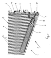
- Fig. 1 shows a section of a refrigerant condenser 1, as shown in FIG 6, an illustrated air conditioner for a motor vehicle having a Refrigerant circuit with compressor, evaporator, air conditioning and expansion valve, wherein the condenser is integrated in the refrigerant circuit.
- the condenser consists of a rib / tube block 2, which consists of flat tubes 2a and between these arranged corrugated fins 100 constructed and soldered to a block.
- the flat tubes 2a open into a manifold 3, which may be formed in one or two parts and by partitions 4, 5 is divided into individual chambers 6, 7.
- the condenser 1 has another Not shown collecting pipe on the opposite side.
- the headers and the tube / fin block 2 are also together soldered.
- the condenser 1 is traversed by air in the direction of an arrow L. and is in the engine compartment of a vehicle, preferably in front of one Arranged and fixed coolant radiator, not shown.
- Tube / rib block 2 has an end face 8, which acts directly on the air is, by a non-illustrated grille in the engine compartment of the vehicle arrives.
- a dryer bottle 9 is arranged, the has an elongated, cylindrical formation and lying, d. H. parallel is arranged to the tubes 2a of the tube / rib block 2.
- the dryer bottle 9 is - attached to the capacitor 1 - not visible here and incorporated into the refrigerant circuit of the automotive air conditioning system.
- the refrigerant enters via an inlet pipe 10 in the vapor state the condenser 1, flows through this in a meandering, u. a.
- the dryer bottle 9 has an end flange 11 for the refrigerant inlet. and exit.
- a refrigerant outlet pipe 12 connected to the end flange 11th the dryer bottle 9 leads and is fixed there.
- a refrigerant connecting pipe 13 is connected, which is the refrigerant from the dryer bottle in the refrigerant circuit, not shown returns.
- the dryer bottle 9 is thus U-shaped, d. H.
- the refrigerant by a not shown Dryer material eg, a silica gel present in granular form
- 9 can not in the dryer bottle shown screens for cleaning the refrigerant of dirt particles arranged be.
- the dryer bottle 9 is - as the illustration shows - full exposed to the air flow and is therefore cooled from the outside.
- the coat of the Dryer bottle 9 is therefore made of a material with good thermal conductivity, z. B. aluminum.
- the airflow direction behind the dryer bottle 9 located rows of tubes of the subcooling are indeed through the Drier bottle 9 covered, but this cover effect is due to the reduced round cross-section of the dryer bottle 9, since the Cooling air flow at least partially behind the dryer bottle. 9 closes.
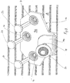
- Fig. 2 shows a view of the dryer bottle 9 in the air flow direction or with a view to the end face 8 of the condenser 1.
- the dryer bottle 9 is by means of two tabs 9a, 9b and two with the tube / rib block second riveted holding elements 14, 15 attached to the capacitor 1. These holding elements are described in more detail below.
- Fig. 3 shows the holding element 14, which is designed as a sheet metal part and a flat portion 14a with three holes 16, 17, 18 has.
- a flat, bent hook 14b which has a threaded bore 19 for receiving a set screw 20.
- the holes 16, 17, 18 serve to receive rivets 21, 22, 23rd
- Fig. 4 shows the holding element 14 from its back, d. H. from the side, the rests on the end face 8 of the capacitor 1.
- the holes 16, 17, 18 are set so that they are respectively arranged between tubes 2a and the ribs lying between the tubes 2a can be pierced.
- On the back (the lee side) of the capacitor 1 and the Tube / rib block 2 are Unterlegeterion 24, 25, 26 for receiving the Rivet shanks and provided as an abutment for the Gegennietkexcellent.
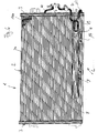
- Fig. 5 again shows the end face 8 (as in Fig. 3) of the tube / rib block 2 with mounted, d. H. riveted holding element 14.
- the rivets 21, 22, 23 are stuck with their rivet shanks through the interstices of the flat tubes 2a and riveted to the back of the tube / fin block 2, wherein the Unterlegeterion 24, 25, 26 as a contact surface for the not shown serve upset rivet heads.
- the dryer bottle 9, not shown can now with the help of tabs 9a, 9b (indicated in FIG Fig. 2) hooked into the hooks 14 (15), adjusted and positioned and then be fixed with the screw 20. This is the dryer bottle 9 sufficiently fixed to the capacitor 1 and may optionally again (by loosening the screws 20) dissolved and dismantled become.
Landscapes
- Engineering & Computer Science (AREA)
- Physics & Mathematics (AREA)
- Thermal Sciences (AREA)
- Mechanical Engineering (AREA)
- General Engineering & Computer Science (AREA)
- Air-Conditioning For Vehicles (AREA)
- Drying Of Solid Materials (AREA)
- Heat-Exchange Devices With Radiators And Conduit Assemblies (AREA)
Abstract
Description
- Fig. 1
- eine perspektivische Teilansicht eines Kältemittelkondensators mit Trocknerflasche,
- Fig. 2
- eine Ansicht der Trocknerflasche vor dem Kondensator,
- Fig. 3
- ein Halteelement mit Nieten und Stellschraube,
- Fig. 4
- eine Rückansicht des Halteelements mit Unterlegscheiben,
- Fig. 5
- eine Vorderansicht des Halteelements in montiertem Zustand und
- Fig. 6
- einen Kondensator.
Claims (7)
- Kältemittelkondensator, insbesondere für eine Kraftfahrzeug-Klimaanlage, bestehend aus einem Rohr/Rippenblock (2) und beiderseits angeordneten Sammelrohren (3) mit einem Kältemitteleinlass (10) und einem Kältemittelauslass (12), mit einer mittels Halteelementen am Rohr/Rippenblock (2) des Kondensators (1) befestigten, dem Kondensator (1) kältemittelseitig nachgeschalteten Trocknerflasche (9), wobei der Rohr/Rippenblock (2) eine von Luft beaufschlagte Stirnfläche (8) aufweist, dadurch gekennzeichnet, dass die Trocknerflasche (9) in Luftströmungsrichtung L vor der Stirnfläche (8) angeordnet ist.
- Kondensator nach Anspruch 1, dadurch gekennzeichnet, dass die Trocknerflasche (9) im unteren Bereich der Stirnfläche (8) angeordnet ist.
- Kondensator nach Anspruch 1 oder 2, dadurch gekennzeichnet, dass der Kondensator (1) eine Unterkühlstrecke aufweist und dass die Trocknerflasche (9) in Luftströmungsrichtung L vor der Unterkühlstrecke angeordnet ist.
- Kondensator nach Anspruch 1, 2 oder 3, dadurch gekennzeichnet, dass die Trocknerflasche (9) einen etwa kreisrunden Querschnitt und einen Stirnflansch (11) aufweist, an dem eine Kältemitteleintritts- und eine Kältemittelaustrittsleitung (12, 13) befestigt sind.
- Kondensator nach Anspruch 3 und 4, dadurch gekennzeichnet, dass die Kältemitteleintrittsleitung (12) mit einer der Unterkühlstrecke zugeordneten Kammer (7) des Sammelrohres (3) verbunden ist.
- Kondensator nach einem der Ansprüche 1 bis 5, dadurch gekennzeichnet, dass das die Haltelemente (14, 15) als Blechteile ausgebildet und mit dem Rohr/Rippenblock (2) vernietet sind.
- Kondensator nach Anspruch 6, dadurch gekennzeichnet, dass die Trocknerflasche (9) Laschen (9a, 9b) und die Blechteile (14, 15) Haken (14b) aufweisen und dass die Laschen (9a, 9b) in die Haken (14b) eingesetzt und durch eine Stellschraube (20) gesichert sind.
Applications Claiming Priority (2)
| Application Number | Priority Date | Filing Date | Title |
|---|---|---|---|
| DE10336621A DE10336621A1 (de) | 2003-08-05 | 2003-08-05 | Kältemittelkondensator mit Trocknerflasche |
| DE10336621 | 2003-08-05 |
Publications (3)
| Publication Number | Publication Date |
|---|---|
| EP1505358A2 true EP1505358A2 (de) | 2005-02-09 |
| EP1505358A3 EP1505358A3 (de) | 2007-12-05 |
| EP1505358B1 EP1505358B1 (de) | 2009-09-09 |
Family
ID=33547172
Family Applications (1)
| Application Number | Title | Priority Date | Filing Date |
|---|---|---|---|
| EP04018065A Expired - Fee Related EP1505358B1 (de) | 2003-08-05 | 2004-07-30 | Kältemittelkondensator mit Trocknerflasche |
Country Status (3)
| Country | Link |
|---|---|
| EP (1) | EP1505358B1 (de) |
| AT (1) | ATE442558T1 (de) |
| DE (2) | DE10336621A1 (de) |
Cited By (3)
| Publication number | Priority date | Publication date | Assignee | Title |
|---|---|---|---|---|
| JP2015163835A (ja) * | 2014-02-20 | 2015-09-10 | モーディーン・マニュファクチャリング・カンパニーModine Manufacturing Company | はんだ付け熱交換器 |
| WO2016009014A1 (fr) * | 2014-07-16 | 2016-01-21 | Valeo Systemes Thermiques | Bouteille de condenseur adaptée pour une utilisation dans un circuit de climatisation, plus particulièrement le circuit de climatisation d'un véhicule automobile |
| EP3855101A1 (de) * | 2020-01-22 | 2021-07-28 | Valeo Autosystemy SP. Z.O.O. | Wärmetauscher mit horizontal positioniertem sammler-trockner |
Citations (4)
| Publication number | Priority date | Publication date | Assignee | Title |
|---|---|---|---|---|
| US5394710A (en) * | 1992-11-06 | 1995-03-07 | Nippondensco Co., Ltd. | Refrigerating apparatus |
| EP0769666A1 (de) * | 1995-10-18 | 1997-04-23 | Calsonic Corporation | Verflüssiger mit Flüssigkeitsbehälter |
| DE19645502A1 (de) * | 1995-11-22 | 1997-05-28 | Volkswagen Ag | Trockneranordnung am Kältemittel-Kondensator einer Fahrzeug-Klimaanlage |
| JP2000314574A (ja) * | 1999-04-28 | 2000-11-14 | Showa Alum Corp | レシーバータンク付きコンデンサ |
Family Cites Families (4)
| Publication number | Priority date | Publication date | Assignee | Title |
|---|---|---|---|---|
| DE29624264U1 (de) * | 1995-11-22 | 2001-08-16 | Volkswagen Ag | Trockneranordnung am Kältemittel-Kondensator einer Fahrzeug-Klimaanlage |
| JP2000039232A (ja) * | 1998-07-23 | 2000-02-08 | Sanden Corp | 受液器組込凝縮器 |
| JP4569041B2 (ja) * | 2000-07-06 | 2010-10-27 | 株式会社デンソー | 車両用冷凍サイクル装置 |
| EP1202007A1 (de) * | 2000-10-25 | 2002-05-02 | Skg Italiana Spa | Verflüssiger und Trockner |
-
2003
- 2003-08-05 DE DE10336621A patent/DE10336621A1/de not_active Withdrawn
-
2004
- 2004-07-30 EP EP04018065A patent/EP1505358B1/de not_active Expired - Fee Related
- 2004-07-30 AT AT04018065T patent/ATE442558T1/de not_active IP Right Cessation
- 2004-07-30 DE DE502004010030T patent/DE502004010030D1/de active Active
Patent Citations (4)
| Publication number | Priority date | Publication date | Assignee | Title |
|---|---|---|---|---|
| US5394710A (en) * | 1992-11-06 | 1995-03-07 | Nippondensco Co., Ltd. | Refrigerating apparatus |
| EP0769666A1 (de) * | 1995-10-18 | 1997-04-23 | Calsonic Corporation | Verflüssiger mit Flüssigkeitsbehälter |
| DE19645502A1 (de) * | 1995-11-22 | 1997-05-28 | Volkswagen Ag | Trockneranordnung am Kältemittel-Kondensator einer Fahrzeug-Klimaanlage |
| JP2000314574A (ja) * | 1999-04-28 | 2000-11-14 | Showa Alum Corp | レシーバータンク付きコンデンサ |
Cited By (6)
| Publication number | Priority date | Publication date | Assignee | Title |
|---|---|---|---|---|
| JP2015163835A (ja) * | 2014-02-20 | 2015-09-10 | モーディーン・マニュファクチャリング・カンパニーModine Manufacturing Company | はんだ付け熱交換器 |
| US10209014B2 (en) | 2014-02-20 | 2019-02-19 | Modine Manufacturing Company | Brazed heat exchanger |
| WO2016009014A1 (fr) * | 2014-07-16 | 2016-01-21 | Valeo Systemes Thermiques | Bouteille de condenseur adaptée pour une utilisation dans un circuit de climatisation, plus particulièrement le circuit de climatisation d'un véhicule automobile |
| FR3023907A1 (fr) * | 2014-07-16 | 2016-01-22 | Valeo Systemes Thermiques | Bouteille de condenseur adaptee pour une utilisation dans un circuit de climatisation, plus particulierement le circuit de climatisation d'un vehicule automobile |
| EP3855101A1 (de) * | 2020-01-22 | 2021-07-28 | Valeo Autosystemy SP. Z.O.O. | Wärmetauscher mit horizontal positioniertem sammler-trockner |
| WO2021148536A1 (en) * | 2020-01-22 | 2021-07-29 | Valeo Autosystemy Sp. Z O.O. | A heat exchanger with horizontally positioned receiver drier |
Also Published As
| Publication number | Publication date |
|---|---|
| ATE442558T1 (de) | 2009-09-15 |
| EP1505358A3 (de) | 2007-12-05 |
| DE502004010030D1 (de) | 2009-10-22 |
| DE10336621A1 (de) | 2005-03-10 |
| EP1505358B1 (de) | 2009-09-09 |
Similar Documents
| Publication | Publication Date | Title |
|---|---|---|
| EP0668986B1 (de) | Kondensator für eine klimaanlage eines fahrzeuges | |
| EP1724536B1 (de) | Wärmetauscher mit Akkumulator | |
| AT411979B (de) | Kondensator für eine klimaanlage, insbesondere für eine klimaanlage eines kraftfahrzeuges | |
| DE102010026507A1 (de) | Kältemittelkondensatormodul | |
| DE102008048920A1 (de) | Verdampfereinheit | |
| DE112012005008T5 (de) | Wärmetauscher | |
| EP1757888B1 (de) | Anordnung zweier Wärmeübertrager | |
| EP3313677B1 (de) | Kondensatoreinheit einer aufdachklimaanlage | |
| DE19655397B4 (de) | Trockneranordnung am Kältemittel-Kondensator einer Fahrzeug-Klimaanlage | |
| DE19912381B4 (de) | Kondensator | |
| DE102011080673B4 (de) | Kältemittelkondensatorbaugruppe | |
| EP1684032B1 (de) | Kondensator für eine Klimaanlage, insbesondere eines Kraftfahrzeuges | |
| EP1505358B1 (de) | Kältemittelkondensator mit Trocknerflasche | |
| DE102006004414A1 (de) | Kühleinheit | |
| EP2606292A1 (de) | Kältemittelkondensatorbaugruppe | |
| WO2004099687A1 (de) | Vorrichtung zum kondensieren eines kältemittels | |
| DE19800739B4 (de) | Klimaanlage | |
| EP2108912B1 (de) | Kondensator, insbesondere für eine Kraftfahrzeug-Klimaanlage | |
| WO2004065884A1 (de) | Wärmeübertrager | |
| DE3216948A1 (de) | Aussenwaermeaustauscher und -waermeaustauschvorrichtung | |
| EP1577627B1 (de) | Kondensator für Klimaanlagen von Kraftfahrzeugen | |
| DE102016201027A1 (de) | Verdampferanordnung, Klimatisierungseinrichtung und Betriebsverfahren dafür | |
| EP2376859A2 (de) | Kältegerät | |
| DE10032677C2 (de) | Kondensatoranordnung einer Klimaanlage, insbesondere in einem Kraftfahrzeug | |
| EP1310760A1 (de) | Kältemittelkondensator |
Legal Events
| Date | Code | Title | Description |
|---|---|---|---|
| PUAI | Public reference made under article 153(3) epc to a published international application that has entered the european phase |
Free format text: ORIGINAL CODE: 0009012 |
|
| AK | Designated contracting states |
Kind code of ref document: A2 Designated state(s): AT BE BG CH CY CZ DE DK EE ES FI FR GB GR HU IE IT LI LU MC NL PL PT RO SE SI SK TR |
|
| AX | Request for extension of the european patent |
Extension state: AL HR LT LV MK |
|
| PUAL | Search report despatched |
Free format text: ORIGINAL CODE: 0009013 |
|
| AK | Designated contracting states |
Kind code of ref document: A3 Designated state(s): AT BE BG CH CY CZ DE DK EE ES FI FR GB GR HU IE IT LI LU MC NL PL PT RO SE SI SK TR |
|
| AX | Request for extension of the european patent |
Extension state: AL HR LT LV MK |
|
| 17P | Request for examination filed |
Effective date: 20080605 |
|
| 17Q | First examination report despatched |
Effective date: 20080701 |
|
| AKX | Designation fees paid |
Designated state(s): AT DE FR IT |
|
| GRAP | Despatch of communication of intention to grant a patent |
Free format text: ORIGINAL CODE: EPIDOSNIGR1 |
|
| GRAS | Grant fee paid |
Free format text: ORIGINAL CODE: EPIDOSNIGR3 |
|
| GRAA | (expected) grant |
Free format text: ORIGINAL CODE: 0009210 |
|
| AK | Designated contracting states |
Kind code of ref document: B1 Designated state(s): AT DE FR IT |
|
| REF | Corresponds to: |
Ref document number: 502004010030 Country of ref document: DE Date of ref document: 20091022 Kind code of ref document: P |
|
| PLBE | No opposition filed within time limit |
Free format text: ORIGINAL CODE: 0009261 |
|
| STAA | Information on the status of an ep patent application or granted ep patent |
Free format text: STATUS: NO OPPOSITION FILED WITHIN TIME LIMIT |
|
| 26N | No opposition filed |
Effective date: 20100610 |
|
| PGFP | Annual fee paid to national office [announced via postgrant information from national office to epo] |
Ref country code: FR Payment date: 20100802 Year of fee payment: 7 |
|
| PG25 | Lapsed in a contracting state [announced via postgrant information from national office to epo] |
Ref country code: IT Free format text: LAPSE BECAUSE OF FAILURE TO SUBMIT A TRANSLATION OF THE DESCRIPTION OR TO PAY THE FEE WITHIN THE PRESCRIBED TIME-LIMIT Effective date: 20090909 |
|
| PG25 | Lapsed in a contracting state [announced via postgrant information from national office to epo] |
Ref country code: AT Free format text: LAPSE BECAUSE OF NON-PAYMENT OF DUE FEES Effective date: 20100730 |
|
| REG | Reference to a national code |
Ref country code: FR Ref legal event code: ST Effective date: 20120330 |
|
| PG25 | Lapsed in a contracting state [announced via postgrant information from national office to epo] |
Ref country code: FR Free format text: LAPSE BECAUSE OF NON-PAYMENT OF DUE FEES Effective date: 20110801 |
|
| REG | Reference to a national code |
Ref country code: DE Ref legal event code: R082 Ref document number: 502004010030 Country of ref document: DE Representative=s name: GRAUEL, ANDREAS, DIPL.-PHYS. DR. RER. NAT., DE |
|
| REG | Reference to a national code |
Ref country code: DE Ref legal event code: R081 Ref document number: 502004010030 Country of ref document: DE Owner name: MAHLE INTERNATIONAL GMBH, DE Free format text: FORMER OWNER: BEHR GMBH & CO. KG, 70469 STUTTGART, DE Effective date: 20150224 Ref country code: DE Ref legal event code: R082 Ref document number: 502004010030 Country of ref document: DE Representative=s name: GRAUEL, ANDREAS, DIPL.-PHYS. DR. RER. NAT., DE Effective date: 20150224 |
|
| PGFP | Annual fee paid to national office [announced via postgrant information from national office to epo] |
Ref country code: DE Payment date: 20200915 Year of fee payment: 17 |
|
| REG | Reference to a national code |
Ref country code: DE Ref legal event code: R119 Ref document number: 502004010030 Country of ref document: DE |
|
| PG25 | Lapsed in a contracting state [announced via postgrant information from national office to epo] |
Ref country code: DE Free format text: LAPSE BECAUSE OF NON-PAYMENT OF DUE FEES Effective date: 20220201 |