EP1504964A1 - Befestigungseinrichtung zur Befestigung eines Lenkstockmoduls an einem Lenkstock und Lenkstockmodul - Google Patents
Befestigungseinrichtung zur Befestigung eines Lenkstockmoduls an einem Lenkstock und Lenkstockmodul Download PDFInfo
- Publication number
- EP1504964A1 EP1504964A1 EP04014208A EP04014208A EP1504964A1 EP 1504964 A1 EP1504964 A1 EP 1504964A1 EP 04014208 A EP04014208 A EP 04014208A EP 04014208 A EP04014208 A EP 04014208A EP 1504964 A1 EP1504964 A1 EP 1504964A1
- Authority
- EP
- European Patent Office
- Prior art keywords
- wedge
- fastening device
- clamping element
- steering column
- sections
- Prior art date
- Legal status (The legal status is an assumption and is not a legal conclusion. Google has not performed a legal analysis and makes no representation as to the accuracy of the status listed.)
- Granted
Links
- 239000002184 metal Substances 0.000 claims description 6
- 230000000295 complement effect Effects 0.000 claims description 2
- 239000000463 material Substances 0.000 description 3
- 230000005489 elastic deformation Effects 0.000 description 2
- 230000036316 preload Effects 0.000 description 2
- 238000005452 bending Methods 0.000 description 1
- 230000006835 compression Effects 0.000 description 1
- 238000007906 compression Methods 0.000 description 1
- 230000000694 effects Effects 0.000 description 1
- 230000002349 favourable effect Effects 0.000 description 1
- 238000003780 insertion Methods 0.000 description 1
- 230000037431 insertion Effects 0.000 description 1
- 230000002028 premature Effects 0.000 description 1
- 230000007704 transition Effects 0.000 description 1
Images




Classifications
-
- B—PERFORMING OPERATIONS; TRANSPORTING
- B62—LAND VEHICLES FOR TRAVELLING OTHERWISE THAN ON RAILS
- B62D—MOTOR VEHICLES; TRAILERS
- B62D1/00—Steering controls, i.e. means for initiating a change of direction of the vehicle
- B62D1/02—Steering controls, i.e. means for initiating a change of direction of the vehicle vehicle-mounted
- B62D1/16—Steering columns
-
- B—PERFORMING OPERATIONS; TRANSPORTING
- B60—VEHICLES IN GENERAL
- B60Q—ARRANGEMENT OF SIGNALLING OR LIGHTING DEVICES, THE MOUNTING OR SUPPORTING THEREOF OR CIRCUITS THEREFOR, FOR VEHICLES IN GENERAL
- B60Q1/00—Arrangement of optical signalling or lighting devices, the mounting or supporting thereof or circuits therefor
- B60Q1/02—Arrangement of optical signalling or lighting devices, the mounting or supporting thereof or circuits therefor the devices being primarily intended to illuminate the way ahead or to illuminate other areas of way or environments
- B60Q1/04—Arrangement of optical signalling or lighting devices, the mounting or supporting thereof or circuits therefor the devices being primarily intended to illuminate the way ahead or to illuminate other areas of way or environments the devices being headlights
- B60Q1/14—Arrangement of optical signalling or lighting devices, the mounting or supporting thereof or circuits therefor the devices being primarily intended to illuminate the way ahead or to illuminate other areas of way or environments the devices being headlights having dimming means
- B60Q1/1446—Arrangement of optical signalling or lighting devices, the mounting or supporting thereof or circuits therefor the devices being primarily intended to illuminate the way ahead or to illuminate other areas of way or environments the devices being headlights having dimming means controlled by mechanically actuated switches
- B60Q1/1453—Hand actuated switches
- B60Q1/1461—Multifunction switches for dimming headlights and controlling additional devices, e.g. for controlling direction indicating lights
Definitions
- the invention relates to a fastening device for Attaching a steering column module to a jacket pipe of a Steering racks and a steering column module.
- Steering stick modules usually in the area of the steering wheel a vehicle are arranged, have a number of Switches, such as direction switches, Dipped beam switch, Windscreen wiper switch or the like.
- the steering column modules accommodate steering angle sensors, with where the angle of rotation of the steering column can be detected.
- the steering column modules serve to accommodate a so-called clock spring, with the signals, the steering wheel side to be generated, with the steering wheel not mitcardende Components are transferred.
- Coil springs are in the Usually designed as a ribbon cable, the snail-shaped around the axis of rotation of the steering column or the steering wheel are wound up.
- Known steering column modules include also axle offset compensation means, the axle replacement the longitudinal axis of the steering column to the axis of rotation of a rotor compensate for a clock spring or a steering angle sensor.
- the present invention is therefore the task underlying, a fastening device for attachment to propose a longitudinal rod module to the casing pipe, which remedies the disadvantages of the prior art.
- a simple, safe and durable Attachment of the steering column module can be achieved.
- a Fastening device with a between the casing pipe and a mounting portion of the steering column module can be arranged, sleeve-like clamping element, the Wedge sections for wedge clamping when rotated around the Longitudinal axis with at least substantially parallel to Having longitudinal axis extending wedge surfaces.
- the Twisting of the clamping element occurs on both sides of the Wedge section advantageously a line or Surface pressure against the jacket tube or against the Attachment section on.
- the wedge sections point in Cross section or viewed in the direction of the longitudinal axis Wedge profile on.
- the clamping elements can indirectly and / or directly on the jacket tube and / or the corresponding Attachment section. It can Intermediate elements between the clamping element and the Jacket tube or the attachment portion be present.
- the jacket tube can be used as the steering column at least Sectionally surrounding steering column casing pipe be educated. It can also be used as a separate, on the Steering column jacket pipe can be provided anordenbares component. Due to the wedge clamping can on the one hand a rotation the steering column module relative to the jacket tube and the other a backup can be achieved in the axial direction.
- the wedge portion are at least largely identical and even over the circumference of the Clamping elements arranged distributed.
- This can be a Self - centering of the steering column module when turning the steering column module Wedge element to the longitudinal axis of the jacket tube or the Steering column done.
- a good self-centering results when a total of three wedge sections are provided. Due to the self-centering can Achsversatzaus Dermasmittel omitted, the one Axial offset, for example, on the steering column or Steering wheel side rotor of a coil spring or a Steering angle sensor with respect to one on the steering column module arranged or formed by the steering column module Balance the stator.
- the clamping element and / or the jacket tube can a at least partially open or closed cross-section exhibit.
- Longitudinal slots may be provided.
- the wedge sections at least largely over the entire length of the clamping element extend.
- the wedge sections are preferably the same length as corresponding to the wedge sections Guide surfaces on the jacket tube. This will be a Risk of tipping the steering column module against the Sheath tube prevented.
- the area or Line with which a surface or line pressure takes place increased.
- the clamping element may be formed so that the radial inner surface of the clamping element a has circular cross-section.
- the clamping element is advantageously over this circular cross section, the surrounds the jacket tube, can be pushed onto the jacket tube.
- the Wedge sections with the jacket tube or on Attachment section provided counter wedge sections correspond.
- the counter wedge sections are like this formed in that the wedge portions of the clamping element in axial direction in the counter wedge sections inserted are. When turning the clamping element act respective clamping surfaces of the wedge portions against the Surface of the counter wedge sections.
- the wedge surfaces in such a way are formed that an at least substantially homogeneous Surface pressure or line pressure occurs. hereby The load will be even on a relatively large load Area or distributed along a line. material Damaging voltage peaks are avoided.
- Another, particularly preferred embodiment of the Invention results when the wedge surfaces a have such a small wedge slope that a Self-locking can occur. This will be a unintentional, automatic release of the steering column module from Sheath tube prevented.
- the wedge slope can for example in the range from 1:50 to 1: 200.
- a particularly preferred embodiment of the invention arises when the wedge surfaces in cross-section as eccentric to the longitudinal axis extending circle segments are formed.
- Circular segments can be manufactured be realized in a simple manner. Furthermore they have the advantage that depending on the choice of each Radius even with slight twisting of the clamping element a clamping effect can occur.
- the Counter wedge sections also formed by circle segments enters a favorable, defined line pressure on. Depending on the choice of the circle center of the respective Circular segments and depending on the radius of the circle segment arise more or less steep wedge surfaces.
- Another preferred embodiment of the invention is characterized in that the clamping element between the wedge sections centric to the longitudinal axis extending Has circle segment sections.
- the circle segment sections Consequently, they lie on a circular path around the longitudinal axis of the Clamping element.
- the provision of circular segment sections has the advantage that the clamping element when turning to its Longitudinal axis guided in the region of the circular segment sections can be. A wedge clamping therefore does not occur in the Area of the circle segment section on, but only to the wedge sections.
- the angle that a circle segment section encloses is advantageously about 40 ° to 20 °. Particularly advantageous values result when the angle of the circle segment portion is 90 ° and the angle of Wedge section 30 °.
- the clamping element a having groove-like recess extending in the longitudinal direction extends and adjacent to a wedge portion.
- each wedge section closes such a recess, to the respective steeper flank of the wedge section. This will be a similar compliance of the wedge sections ensuring that achieves a good self-centering becomes.
- a particularly advantageous compliance of the Wedge sections results when the groove-like Recesses also on the side facing away from the jacket tube extend in the circumferential direction.
- This can be the Recesses in particular at least over the length of extend respective wedge portion. This will achieved that elastic deformation of the Wedge sections along a substantially parallel to the Longitudinal axis running bending line can be done so that a very uniform in the axial direction line or Surface pressure is achieved.
- the radial outside of the clamping element torsional means have, with which a rotation of the clamping element can be enabled.
- the twisting means can, for example, in the range of be provided free end edge of the clamping element.
- the torsion means comprise a Helical toothing for engagement of a counter toothing a locking bolt is suitable.
- a corresponding adjusting bolt for example, transversely to Longitudinal axis of the clamping element may be arranged, a Twisting the clamping element in a simple manner will be realized.
- the adjusting bolt the example in Steering column module can be arranged stored, points Preferably, an engaging portion, in the known Bolt drivers can intervene.
- the Twisting a recording for a screw in such a way include that the set screw perpendicular to the longitudinal axis is recorded and when turning the screw the Clamping element relative to the steering column module and the Casing tube is twisted.
- the recording shows Advantageously, a thread in which the Adjusting screw can be screwed.
- the adjusting screw supports at the same time with her free end to the Steering column module off. By turning the adjusting screw Consequently, the clamping element rotates about the longitudinal axis, while the set screw is supported on the steering column module.
- the attachment portion on the radially outer, facing away from the clamping element Outside a force absorbing means for receiving the Rotation of the clamping element occurring radial forces having.
- the force absorbing means thus provides Resistance to deformation of the Attachment portion.
- the force receiving means can then as a be formed outside the surrounding metal ring.
- the object mentioned above is also by a Steering column module solved, which is an inventive Fastening device comprises.
- that can Steering column module next to the clamping element and the adjusting bolt and the metal ring.
- FIG. 1 shows a steering column module 10 according to the invention with a fastening device 12 according to the invention shown.
- the steering column module 10 takes not shown Switch on, by means of illustrated levers 14th are operable.
- the steering column switch module 10 includes a central breakthrough 16, in which the one end of a Steering column 18 protrudes. This end of the steering column is in assembled state with a steering wheel, not shown rotatably connected.
- the steering column 18 is in the range of Steering column module 10 surrounded by a jacket tube 20.
- the steering column module 10 has a Attachment section 22 for attachment of the jacket tube 20th on.
- the attachment portion 22 is on the Outer side surrounded by a metal ring 24.
- to Attachment of the steering column module 10 on the casing tube 20 is the attachment portion 22 on the free end 26 of the Jacket tube 20 postponed. Subsequently, by the side facing away from the jacket tube 26 a clamping element 28th between the jacket tube 20 and the attachment portion 22nd pushed.
- the clamping element on the Attachment portion 22 facing the radial outside three identically formed, evenly over the circumference of the clamping element 28 arranged wedge sections 30th having.
- the three wedge sections 30 correspond to the Attachment section 22 provided counter-wedge sections 32.
- the wedge portions 30 and the counter wedge portions 32nd are formed complementary to each other.
- the Wedge sections 30 and the counter wedge sections 32 have Wedge surfaces 31 on, which consist of segments of logarhythmic Spirals exist. Such wedge surfaces are in the figure 5 exemplified on circular wedge profiles.
- the radially inner inner surface 34 of the clamping element 28 has a circular, the jacket tube 26 surrounding Cross-section on.
- the sleeve-like Attachment section 22 has on the radial outer, the clamping element 28 facing away from the outside 36 is a circular cross-section of the Metal ring 24 is surrounded.
- the clamping element 28 For attachment of the Steering rod module 10 on the jacket tube 20 is the clamping element 28 in the cross section shown in Figure 2 opposite in the clockwise direction in the illustrated in Figure 3 Final assembly rotated.
- the metal ring 24 receives the radially acting forces and prevents unwanted deformation of the Fixing section 22.
- the jacket tube 20 has at its free end 26 a Longitudinal slot 38, the conditionally elastic yielding of the jacket tube 26 allows.
- the casing tube 20 acts due to the occurring radial forces conditionally elastic yielding. This results in a certain bias.
- the wedge member 28 To rotate the wedge member, the wedge member 28 the radial outer side of a screw tooth portion 40th on, which can be seen in Figure 4.
- the Screw tooth section 40 acts with an adjusting bolt 42 together.
- the adjusting bolt 42 is in the mounted state in Longitudinal stock module 10 in a torsion receptacle 44 rotatable stored.
- the helical toothing 46 of the adjusting bolt 42 is engaged with the screw tooth portion 40th
- Shu Turning the adjusting bolt 42 for example by means of a Screwdriver, is about the helical teeth 46 and the screw tooth portion 40, the clamping member 28 is rotated.
- the three extend Wedge sections over largely the entire length of the Clamping elements 28. This will cause tilting of the Steering column module 10 relative to the jacket tube 20th counteracted.
- the clamping member 28 acts on the one hand directly against the Jacket tube and on the other hand directly against the Attachment section 22 of the steering column module 10. According to in another embodiment it can be provided that between the clamping part 28 and the steering column module 10 or the jacket tube 20 intermediate elements, for example in shape of pods, are present.
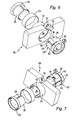
- FIGS. 6 to 11 show a second invention Embodiment.
- Figures 1 to 4 corresponding components are provided with corresponding reference numerals.
- Fastening device 52 for fastening the Steering column module 50 on the jacket tube 20 includes a Clamping element 54, between two adjacent Wedge sections 56 centered to the longitudinal axis Circular segment sections 58 has.
- the wedge surfaces are considered in cross section, as in Figure 8 not as segments of logarithmic spirals, but formed as circle segments.
- the single ones Wedge sections close as seen in cross section, as in Figure 8, an angle ⁇ of about 30 °.
- the individual circle segment sections 58 close an angle ⁇ of about 90 °.
- the clamping element 54 facing side of the Fixing section 22 has counter wedge sections 60, which also has a circular segment-shaped surface exhibit.
- the radius of these surfaces can be the radius the wedge portions 56 correspond.
- FIGS. 6 to 9 it can be seen that adjacent to a wedge portion a longitudinally extending groove-like recess 62 is provided in the clamping element 54. Since each wedge section 56 has a recess 62 connects, a total of three recesses 62 are present.
- the groove-like recesses 62 extend on the Jacket tube 20 side facing away also in the circumferential direction.
- the section of the recesses extending in the circumferential direction extends is indicated in the figures with 64.
- a twist can for example, to a defined stop.
- the screw receptacle 68 includes a vertical to the longitudinal axis extending threaded bore 70 in the one screwed 72 shown in the figure 11 can be.
- the screw receptacle 68 includes a vertical to the longitudinal axis extending threaded bore 70 in the one screwed 72 shown in the figure 11 can be.
- the free is supported End of the adjusting screw 72 on a support 74 of the Steering column module 50 from.
- the screw receiver 68 moves in such a way that the Clamping element 54 against the steering column module 50 to his Longitudinal axis is twisted.
- a Recess 76 provided by the adjusting screw 72nd is accessible and can be twisted.
- the longitudinal slot 38 in the jacket tube 20 is intended for that the steering column module 50 in a defined position can be mounted.
- the steering column module 50 looks to it a positioning pin 76 which, as in FIG. 10 shown in the assembled state in the longitudinal slot 38th intervenes. So that the clamping element 54 without hindrance the positioning pin 76 as far as possible to the free end 26 of the jacket tube 20 can be pushed, it shows a recess 78.
- twisting means are designed such that during axial insertion of the clamping element in the central breakthrough 16 via appropriate guidance means a twisting of the clamping element can take place.
- guide pins can be attached to the clamping element be provided in the on the attachment portion provided guideways intervene.
- the guideways can be designed to give a forced twist cause the clamping element, if this in the axial direction is introduced into the central breakthrough 16.
- Securing means can be used, for example, as rest or Be formed clamping elements.
Landscapes
- Engineering & Computer Science (AREA)
- Mechanical Engineering (AREA)
- Chemical & Material Sciences (AREA)
- Combustion & Propulsion (AREA)
- Transportation (AREA)
- Steering Controls (AREA)
- Clamps And Clips (AREA)
- Mutual Connection Of Rods And Tubes (AREA)
Abstract
Description
- Figur 1
- eine perspektivische Explosionsdarstellung eines erfindungsgemäßen Lenkstockmoduls,
- Figur 2
- einen Querschnitt durch die Befestigungseinrichtung des Lenkstockmoduls gemäß Figur 1 in einer Vormontageposition,
- Figur 3
- den Querschnitt gemäß Figur 2 in der Endmontageposition,
- Figur 4
- die Vorderansicht des Lenkstockmoduls gemäß Figur 1,
- Figur 5
- einen Querschnitt durch ein Kreiskeil-Profil,
- Figur 6
- eine perspektivische Explosionsdarstellung eines zweiten erfindungsgemäßen Lenkstockmoduls,
- Figur 7
- eine andere Ansicht des Lenkstockmoduls gemäß Figur 6,
- Figur 8
- einen Querschnitt durch die Befestigungseinrichtung des Lenkstockmoduls gemäß Figur 6 und 7,
- Figur 9
- das Klemmelement der Befestigungseinrichtung des Lenkstockmoduls gemäß Figur 6 und 7,
- Figur 10
- eine perspektivische Ansicht des am Mantelrohr befestigten Lenkstockmoduls gemäß Figur 6 und 7 und
- Figur 11
- eine Vorderansicht des Lenkstockmoduls gemäß Figur 10.
Claims (24)
- Befestigungseinrichtung (12, 52) zur Befestigung eines Lenkstockmoduls (10) an dem Mantelrohr (20) eines Lenkstocks, mit einem zwischen dem Mantelrohr (20) und einem Befestigungsabschnitt (22) des Lenkstockmoduls (10) anordenbaren, hülsenartigen Klemmelement (28, 54), das Keilabschnitte (30, 56) mit wenigstens weitgehend parallel zur Längsachse verlaufenden Keilflächen (31) zur Keilklemmung bei Drehung um die Längsachse aufweist.
- Befestigungseinrichtung (12, 52) nach Anspruch 1, dadurch gekennzeichnet, dass die Keilabschnitte (30, 56) wenigstens weitgehend identisch und gleichmäßig über den Umfang des Klemmelements (28, 54) verteilt angeordnet sind.
- Befestigungseinrichtung (12, 52) nach Anspruch 1 oder 2, dadurch gekennzeichnet, dass das Klemmelement (28, 54) und/oder das Mantelrohr (20) einen wenigstens teilweise offenen oder geschlossenen Querschnitt aufweist.
- Befestigungseinrichtung (12, 52) nach Anspruch 1, 2 oder 3, dadurch gekennzeichnet, dass sich die Keilabschnitte (30) wenigstens weitgehend über die gesamte Länge des Klemmelements (28, 54) erstrecken.
- Befestigungseinrichtung (12, 52) nach einem der vorhergehenden Ansprüche, dadurch gekennzeichnet, dass die radial innen liegende Innenfläche (34) des Klemmelements (28, 54) einen kreisrunden Querschnitt aufweist.
- Befestigungseinrichtung (12, 52) nach einem der vorhergehenden Ansprüche, dadurch gekennzeichnet, dass die Keilabschnitte (30) auf der radial außen liegenden Außenfläche des Klemmelements (28) angeordnet sind.
- Befestigungseinrichtung (12 52) nach einem der vorhergehenden Ansprüche, dadurch gekennzeichnet, dass die Keilabschnitte (30, 56) mit am Mantelrohr (20) beziehungsweise am Befestigungsabschnitt (22) angeordneten, wenigstens weitgehend komplementären Gegenkeilabschnitten (32, 60) korrespondieren.
- Befestigungseinrichtung (12, 52) nach einem der vorhergehenden Ansprüche, dadurch gekennzeichnet, dass die Keilflächen (31) derart ausgebildet sind, dass eine wenigstens weitgehend homogene Flächenpressung oder Linienpressung auftritt.
- Befestigungseinrichtung (12, 52) nach einem der vorhergehenden Ansprüche, dadurch gekennzeichnet, dass die Keilflächen (31) eine derart kleine Keilsteigung aufweisen, dass eine Selbsthemmung auftreten kann.
- Befestigungseinrichtung (12, 52) nach einem der vorhergehenden Ansprüche, dadurch gekennzeichnet, dass die Keilflächen (31) im Querschnitt als exzentrisch zur Längsachse (A) verlaufende Kreissegmente ausgebildet sind.
- Befestigungseinrichtung (12) nach einem der vorhergehenden Ansprüche 1 bis 9, dadurch gekennzeichnet, dass die Keilflächen (31) im Querschnitt als Segmente logarithmischer Spiralen ausgebildet sind.
- Befestigungseinrichtung (52) nach einem der vorhergehenden Ansprüche, dadurch gekennzeichnet, dass das Klemmelement (54) zwischen den Keilabschnitten zentrisch zur Längsachse verlaufende Kreissegmentabschnitte (58) aufweist.
- Befestigungseinrichtung (52) nach Anspruch 12, dadurch gekennzeichnet, dass im Querschnitt gesehen die Kreissegmentabschnitte (58) je einen Winkel (α) einschleißen, der 2,5 bis 3,5 mal größer ist, als der Winkel (β), den die einzelnen Keilabschnitte (56) einschließen.
- Befestigungseinrichtung (52) nach Anspruch 12 oder 13, dadurch gekennzeichnet, dass ein Kreissegmentabschnitt (58) einen Winkel (α) von 80° bis 110° einschließt und dass ein Keilabschnitt (56) einen Winkel (β) von 40° bis 20 ° einschließt.
- Befestigungseinrichtung (52) nach einem der vorhergehenden Ansprüche, dadurch gekennzeichnet, dass angrenzend an einen Keilabschnitt (56) eine sich in Längsrichtung erstreckende nutartige Ausnehmung (62) vorgesehen ist.
- Befestigungseinrichtung nach den Anspruch 12 oder 15, dadurch gekennzeichnet, dass die nutartige Ausnehmung (62) sich auch auf der dem Mantelrohr abgewandten Seite in Umfangsrichtung (64) erstreckt.
- Befestigungseinrichtung (52) nach Anspruch 16, dadurch gekennzeichnet, dass sich die Ausnehmung (64) wenigstens über die Länge des Keilabschnitts (56) in Umfangsrichtung erstreckt.
- Befestigungseinrichtung (12, 52) nach einem der vorhergehenden Ansprüche, dadurch gekennzeichnet, dass das Klemmelement (28, 54) auf der radialen Außenseite Verdrehmittel (40, 68) aufweist, mit denen eine Verdrehung des Klemmelements (28, 54) ermöglicht werden kann.
- Befestigungseinrichtung (12) nach Anspruch 18, dadurch gekennzeichnet, dass die Verdrehmittel eine Schraubenverzahnung (40) umfassen, die zum Eingriff einer Gegenverzahnung (46) eines Stellbolzens (42) geeignet ist.
- Befestigungseinrichtung (52) nach Anspruch 18, dadurch gekennzeichnet, dass die Verdrehmittel eine Aufnahme (68) für eine Stellschraube (72) derart umfassen, dass die Stellschraube senkrecht zur Längsachse (A) aufgenommen wird und beim Verdrehen der Stellschraube (72) das Klemmelement (54) gegenüber dem Lenkstockmodul (50) und dem Mantelrohr (20) verdreht wird.
- Befestigungseinrichtung (12, 52) nach einem der vorhergehenden Ansprüche, dadurch gekennzeichnet, dass der Befestigungsabschnitt (22) auf der radial außen liegenden, dem Klemmelement abgewandten Außenseite (36) ein Kraftaufnahmemittel (24) zur Aufnahme der beim Verdrehen des Klemmelements (28) auftreten radialen Kräfte aufweist.
- Befestigungseinrichtung (12) nach Anspruch 21, dadurch gekennzeichnet, dass die Außenseite (36) des Befestigungsabschnitts im Querschnitt kreisförmig ausgebildet ist.
- Befestigungseinrichtung (12) nach Anspruch 21 oder 22, dadurch gekennzeichnet, dass Kraftaufnahmemittel als ein die Außenseite (36) umgebender Metallring (24) ausgebildet ist.
- Lenkstockmodul (10) umfassend eine Befestigungseinrichtung (12) nach einem der vorhergehenden Ansprüche.
Applications Claiming Priority (4)
| Application Number | Priority Date | Filing Date | Title |
|---|---|---|---|
| DE10330481 | 2003-07-01 | ||
| DE2003130481 DE10330481A1 (de) | 2003-07-01 | 2003-07-01 | Befestigungseinrichtung zur Befestigung eines Lenkstockmoduls an einem Lenkstock und Lenkstockmodul |
| DE10336302 | 2003-07-31 | ||
| DE10336302A DE10336302A1 (de) | 2003-07-01 | 2003-07-31 | Befestigungseinrichtung zur Befestigung eines Lenkstockmoduls an einem Lenkstock und Lenkstockmodul |
Publications (2)
| Publication Number | Publication Date |
|---|---|
| EP1504964A1 true EP1504964A1 (de) | 2005-02-09 |
| EP1504964B1 EP1504964B1 (de) | 2006-07-05 |
Family
ID=33553482
Family Applications (1)
| Application Number | Title | Priority Date | Filing Date |
|---|---|---|---|
| EP04014208A Expired - Lifetime EP1504964B1 (de) | 2003-07-01 | 2004-06-17 | Befestigungseinrichtung zur Befestigung eines Lenkstockmoduls an einem Lenkstock und Lenkstockmodul |
Country Status (3)
| Country | Link |
|---|---|
| EP (1) | EP1504964B1 (de) |
| AT (1) | ATE332252T1 (de) |
| DE (2) | DE10336302A1 (de) |
Cited By (2)
| Publication number | Priority date | Publication date | Assignee | Title |
|---|---|---|---|---|
| WO2011039491A1 (fr) * | 2009-10-02 | 2011-04-07 | Renault S.A.S. | Systeme de fixation d'un module pour haut de colonne de direction |
| FR2977206A1 (fr) * | 2011-06-29 | 2013-01-04 | Peugeot Citroen Automobiles Sa | Systeme de fixation des commandes secondaires situees sous le volant d'un vehicule automobile |
Citations (4)
| Publication number | Priority date | Publication date | Assignee | Title |
|---|---|---|---|---|
| EP0703371A1 (de) * | 1994-09-20 | 1996-03-27 | Magneti Marelli France | Vorrichtung zur Befestigung einer Anordnung an einer Säule, insbesondere für die Befestigung einer elektrischen Schaltvorrichtung an einer Kraftfahrzeuglenksäule |
| FR2749354A1 (fr) * | 1996-05-30 | 1997-12-05 | Valeo Electronique | Support de commutateurs a collier de fixation pour vehicule automobile |
| EP1199223A2 (de) * | 2000-10-20 | 2002-04-24 | Niles Parts Co., Ltd. | Schalterkombination |
| DE10051226A1 (de) * | 2000-10-16 | 2002-04-25 | Eaton Corp | Lenkstockschalter für ein Kraftfahrzeug |
-
2003
- 2003-07-31 DE DE10336302A patent/DE10336302A1/de not_active Ceased
-
2004
- 2004-06-17 DE DE502004000907T patent/DE502004000907D1/de not_active Expired - Lifetime
- 2004-06-17 EP EP04014208A patent/EP1504964B1/de not_active Expired - Lifetime
- 2004-06-17 AT AT04014208T patent/ATE332252T1/de not_active IP Right Cessation
Patent Citations (4)
| Publication number | Priority date | Publication date | Assignee | Title |
|---|---|---|---|---|
| EP0703371A1 (de) * | 1994-09-20 | 1996-03-27 | Magneti Marelli France | Vorrichtung zur Befestigung einer Anordnung an einer Säule, insbesondere für die Befestigung einer elektrischen Schaltvorrichtung an einer Kraftfahrzeuglenksäule |
| FR2749354A1 (fr) * | 1996-05-30 | 1997-12-05 | Valeo Electronique | Support de commutateurs a collier de fixation pour vehicule automobile |
| DE10051226A1 (de) * | 2000-10-16 | 2002-04-25 | Eaton Corp | Lenkstockschalter für ein Kraftfahrzeug |
| EP1199223A2 (de) * | 2000-10-20 | 2002-04-24 | Niles Parts Co., Ltd. | Schalterkombination |
Cited By (3)
| Publication number | Priority date | Publication date | Assignee | Title |
|---|---|---|---|---|
| WO2011039491A1 (fr) * | 2009-10-02 | 2011-04-07 | Renault S.A.S. | Systeme de fixation d'un module pour haut de colonne de direction |
| FR2950850A1 (fr) * | 2009-10-02 | 2011-04-08 | Renault Sa | Systeme de fixation d'un module pour haut de colonne de direction. |
| FR2977206A1 (fr) * | 2011-06-29 | 2013-01-04 | Peugeot Citroen Automobiles Sa | Systeme de fixation des commandes secondaires situees sous le volant d'un vehicule automobile |
Also Published As
| Publication number | Publication date |
|---|---|
| ATE332252T1 (de) | 2006-07-15 |
| EP1504964B1 (de) | 2006-07-05 |
| DE502004000907D1 (de) | 2006-08-17 |
| DE10336302A1 (de) | 2005-04-21 |
Similar Documents
| Publication | Publication Date | Title |
|---|---|---|
| EP2334952B1 (de) | Spindeltrieb mit verdrehsicherung | |
| DE102016200102B4 (de) | Aktuator, insbesondere für eine Hinterachslenkung eines Kraftfahrzeuges | |
| EP2776274B1 (de) | Verstellgetriebe, insbesondere zur sitzlängsverstellung eines kfz-sitzes | |
| DE102010050175B4 (de) | Kugelgewindemutter | |
| DE10003305C1 (de) | Sitzverstellvorrichtung für Kraftfahrzeuge mit einem Spindelantrieb | |
| WO2012022310A2 (de) | Vorrichtung zum andrücken einer zahnstange | |
| EP3208152B1 (de) | Abklappvorrichtung für einen aussenspiegel | |
| EP1552097A1 (de) | Getriebevorrichtung, insbesondere für verstelleinrichtungen in kraftfahrzeugen | |
| DE102017209563A1 (de) | Loslager, Lenkgetriebe und Lenksystem | |
| EP0751883B1 (de) | Kupplung zwischen der gurtwelle eines gurtaufrollers und einem gurtstraffer-drehantrieb | |
| DE102009038317A1 (de) | Verstellbare Lenksäule für ein Kraftfahrzeug | |
| DE102005051220A1 (de) | Servolenkung | |
| DE102017211461A1 (de) | Lenkgetriebe | |
| DE102012021102A1 (de) | Strebe mit einer durchgehenden Öffnung, insbesondere zur Versteifung eines Kraftfahrzeuges | |
| EP1504964B1 (de) | Befestigungseinrichtung zur Befestigung eines Lenkstockmoduls an einem Lenkstock und Lenkstockmodul | |
| DE10337252B4 (de) | Gurtspule für einen Gurtaufroller | |
| DE102010009155B4 (de) | Gurtstraffer | |
| DE10330481A1 (de) | Befestigungseinrichtung zur Befestigung eines Lenkstockmoduls an einem Lenkstock und Lenkstockmodul | |
| WO2019134814A1 (de) | Lenkgetriebe für ein kraftfahrzeug | |
| DE102022211973A1 (de) | Lenkgetriebe für ein Steer-by-Wire-Lenksystem | |
| DE102018110459A1 (de) | Radlagereinheit | |
| DE102004039253B4 (de) | Haltevorrichtung für einen Bowdenzug sowie Fahrzeugsitz | |
| EP1439978B1 (de) | Getriebe-antriebseinheit mit einem adapter | |
| WO2019086170A1 (de) | Lenksystem | |
| DE102005005400A1 (de) | Vorrichtung zum Andrücken einer Zahnstange an ein mit der Zahnstange in Eingriff stehendes Ritzel |
Legal Events
| Date | Code | Title | Description |
|---|---|---|---|
| PUAI | Public reference made under article 153(3) epc to a published international application that has entered the european phase |
Free format text: ORIGINAL CODE: 0009012 |
|
| AK | Designated contracting states |
Kind code of ref document: A1 Designated state(s): AT BE BG CH CY CZ DE DK EE ES FI FR GB GR HU IE IT LI LU MC NL PL PT RO SE SI SK TR |
|
| AX | Request for extension of the european patent |
Extension state: AL HR LT LV MK |
|
| 17P | Request for examination filed |
Effective date: 20050406 |
|
| AKX | Designation fees paid |
Designated state(s): AT BE BG CH CY CZ DE DK EE ES FI FR GB GR HU IE IT LI LU MC NL PL PT RO SE SI SK TR |
|
| GRAP | Despatch of communication of intention to grant a patent |
Free format text: ORIGINAL CODE: EPIDOSNIGR1 |
|
| GRAS | Grant fee paid |
Free format text: ORIGINAL CODE: EPIDOSNIGR3 |
|
| GRAA | (expected) grant |
Free format text: ORIGINAL CODE: 0009210 |
|
| RIN1 | Information on inventor provided before grant (corrected) |
Inventor name: HASCH, MARTIN Inventor name: GRUENER, ROLAND Inventor name: BINDER, BERND Inventor name: SIMONIS, KARL Inventor name: SUCHANEK, JUERGEN Inventor name: LIPFERT, RAINER |
|
| AK | Designated contracting states |
Kind code of ref document: B1 Designated state(s): AT BE BG CH CY CZ DE DK EE ES FI FR GB GR HU IE IT LI LU MC NL PL PT RO SE SI SK TR |
|
| PG25 | Lapsed in a contracting state [announced via postgrant information from national office to epo] |
Ref country code: PL Free format text: LAPSE BECAUSE OF FAILURE TO SUBMIT A TRANSLATION OF THE DESCRIPTION OR TO PAY THE FEE WITHIN THE PRESCRIBED TIME-LIMIT Effective date: 20060705 Ref country code: FI Free format text: LAPSE BECAUSE OF FAILURE TO SUBMIT A TRANSLATION OF THE DESCRIPTION OR TO PAY THE FEE WITHIN THE PRESCRIBED TIME-LIMIT Effective date: 20060705 Ref country code: CZ Free format text: LAPSE BECAUSE OF FAILURE TO SUBMIT A TRANSLATION OF THE DESCRIPTION OR TO PAY THE FEE WITHIN THE PRESCRIBED TIME-LIMIT Effective date: 20060705 Ref country code: IT Free format text: LAPSE BECAUSE OF FAILURE TO SUBMIT A TRANSLATION OF THE DESCRIPTION OR TO PAY THE FEE WITHIN THE PRESCRIBED TIME-LIMIT;WARNING: LAPSES OF ITALIAN PATENTS WITH EFFECTIVE DATE BEFORE 2007 MAY HAVE OCCURRED AT ANY TIME BEFORE 2007. THE CORRECT EFFECTIVE DATE MAY BE DIFFERENT FROM THE ONE RECORDED. Effective date: 20060705 Ref country code: NL Free format text: LAPSE BECAUSE OF FAILURE TO SUBMIT A TRANSLATION OF THE DESCRIPTION OR TO PAY THE FEE WITHIN THE PRESCRIBED TIME-LIMIT Effective date: 20060705 Ref country code: GB Free format text: LAPSE BECAUSE OF FAILURE TO SUBMIT A TRANSLATION OF THE DESCRIPTION OR TO PAY THE FEE WITHIN THE PRESCRIBED TIME-LIMIT Effective date: 20060705 Ref country code: IE Free format text: LAPSE BECAUSE OF FAILURE TO SUBMIT A TRANSLATION OF THE DESCRIPTION OR TO PAY THE FEE WITHIN THE PRESCRIBED TIME-LIMIT Effective date: 20060705 Ref country code: RO Free format text: LAPSE BECAUSE OF FAILURE TO SUBMIT A TRANSLATION OF THE DESCRIPTION OR TO PAY THE FEE WITHIN THE PRESCRIBED TIME-LIMIT Effective date: 20060705 Ref country code: SK Free format text: LAPSE BECAUSE OF FAILURE TO SUBMIT A TRANSLATION OF THE DESCRIPTION OR TO PAY THE FEE WITHIN THE PRESCRIBED TIME-LIMIT Effective date: 20060705 Ref country code: SI Free format text: LAPSE BECAUSE OF FAILURE TO SUBMIT A TRANSLATION OF THE DESCRIPTION OR TO PAY THE FEE WITHIN THE PRESCRIBED TIME-LIMIT Effective date: 20060705 |
|
| REG | Reference to a national code |
Ref country code: GB Ref legal event code: FG4D Free format text: NOT ENGLISH |
|
| REG | Reference to a national code |
Ref country code: CH Ref legal event code: EP |
|
| REG | Reference to a national code |
Ref country code: IE Ref legal event code: FG4D Free format text: LANGUAGE OF EP DOCUMENT: GERMAN |
|
| REF | Corresponds to: |
Ref document number: 502004000907 Country of ref document: DE Date of ref document: 20060817 Kind code of ref document: P |
|
| PG25 | Lapsed in a contracting state [announced via postgrant information from national office to epo] |
Ref country code: DK Free format text: LAPSE BECAUSE OF FAILURE TO SUBMIT A TRANSLATION OF THE DESCRIPTION OR TO PAY THE FEE WITHIN THE PRESCRIBED TIME-LIMIT Effective date: 20061005 Ref country code: BG Free format text: LAPSE BECAUSE OF FAILURE TO SUBMIT A TRANSLATION OF THE DESCRIPTION OR TO PAY THE FEE WITHIN THE PRESCRIBED TIME-LIMIT Effective date: 20061005 Ref country code: SE Free format text: LAPSE BECAUSE OF FAILURE TO SUBMIT A TRANSLATION OF THE DESCRIPTION OR TO PAY THE FEE WITHIN THE PRESCRIBED TIME-LIMIT Effective date: 20061005 |
|
| PG25 | Lapsed in a contracting state [announced via postgrant information from national office to epo] |
Ref country code: ES Free format text: LAPSE BECAUSE OF FAILURE TO SUBMIT A TRANSLATION OF THE DESCRIPTION OR TO PAY THE FEE WITHIN THE PRESCRIBED TIME-LIMIT Effective date: 20061016 |
|
| NLV1 | Nl: lapsed or annulled due to failure to fulfill the requirements of art. 29p and 29m of the patents act | ||
| PG25 | Lapsed in a contracting state [announced via postgrant information from national office to epo] |
Ref country code: PT Free format text: LAPSE BECAUSE OF FAILURE TO SUBMIT A TRANSLATION OF THE DESCRIPTION OR TO PAY THE FEE WITHIN THE PRESCRIBED TIME-LIMIT Effective date: 20061205 |
|
| GBV | Gb: ep patent (uk) treated as always having been void in accordance with gb section 77(7)/1977 [no translation filed] |
Effective date: 20060705 |
|
| ET | Fr: translation filed | ||
| REG | Reference to a national code |
Ref country code: IE Ref legal event code: FD4D |
|
| PLBE | No opposition filed within time limit |
Free format text: ORIGINAL CODE: 0009261 |
|
| STAA | Information on the status of an ep patent application or granted ep patent |
Free format text: STATUS: NO OPPOSITION FILED WITHIN TIME LIMIT |
|
| 26N | No opposition filed |
Effective date: 20070410 |
|
| BERE | Be: lapsed |
Owner name: VALEO SCHALTER UND SENSOREN G.M.B.H. Effective date: 20070630 |
|
| PG25 | Lapsed in a contracting state [announced via postgrant information from national office to epo] |
Ref country code: MC Free format text: LAPSE BECAUSE OF NON-PAYMENT OF DUE FEES Effective date: 20070630 |
|
| PG25 | Lapsed in a contracting state [announced via postgrant information from national office to epo] |
Ref country code: BE Free format text: LAPSE BECAUSE OF NON-PAYMENT OF DUE FEES Effective date: 20070630 |
|
| PG25 | Lapsed in a contracting state [announced via postgrant information from national office to epo] |
Ref country code: GR Free format text: LAPSE BECAUSE OF FAILURE TO SUBMIT A TRANSLATION OF THE DESCRIPTION OR TO PAY THE FEE WITHIN THE PRESCRIBED TIME-LIMIT Effective date: 20061006 |
|
| PG25 | Lapsed in a contracting state [announced via postgrant information from national office to epo] |
Ref country code: EE Free format text: LAPSE BECAUSE OF FAILURE TO SUBMIT A TRANSLATION OF THE DESCRIPTION OR TO PAY THE FEE WITHIN THE PRESCRIBED TIME-LIMIT Effective date: 20060705 |
|
| PG25 | Lapsed in a contracting state [announced via postgrant information from national office to epo] |
Ref country code: AT Free format text: LAPSE BECAUSE OF NON-PAYMENT OF DUE FEES Effective date: 20070617 |
|
| REG | Reference to a national code |
Ref country code: CH Ref legal event code: PL |
|
| PG25 | Lapsed in a contracting state [announced via postgrant information from national office to epo] |
Ref country code: CH Free format text: LAPSE BECAUSE OF NON-PAYMENT OF DUE FEES Effective date: 20080630 Ref country code: LI Free format text: LAPSE BECAUSE OF NON-PAYMENT OF DUE FEES Effective date: 20080630 |
|
| PG25 | Lapsed in a contracting state [announced via postgrant information from national office to epo] |
Ref country code: CY Free format text: LAPSE BECAUSE OF FAILURE TO SUBMIT A TRANSLATION OF THE DESCRIPTION OR TO PAY THE FEE WITHIN THE PRESCRIBED TIME-LIMIT Effective date: 20060705 Ref country code: LU Free format text: LAPSE BECAUSE OF NON-PAYMENT OF DUE FEES Effective date: 20070617 |
|
| PG25 | Lapsed in a contracting state [announced via postgrant information from national office to epo] |
Ref country code: TR Free format text: LAPSE BECAUSE OF FAILURE TO SUBMIT A TRANSLATION OF THE DESCRIPTION OR TO PAY THE FEE WITHIN THE PRESCRIBED TIME-LIMIT Effective date: 20060705 Ref country code: HU Free format text: LAPSE BECAUSE OF FAILURE TO SUBMIT A TRANSLATION OF THE DESCRIPTION OR TO PAY THE FEE WITHIN THE PRESCRIBED TIME-LIMIT Effective date: 20070106 |
|
| REG | Reference to a national code |
Ref country code: FR Ref legal event code: PLFP Year of fee payment: 13 |
|
| REG | Reference to a national code |
Ref country code: FR Ref legal event code: PLFP Year of fee payment: 14 |
|
| REG | Reference to a national code |
Ref country code: FR Ref legal event code: PLFP Year of fee payment: 15 |
|
| PGFP | Annual fee paid to national office [announced via postgrant information from national office to epo] |
Ref country code: FR Payment date: 20180627 Year of fee payment: 15 |
|
| PG25 | Lapsed in a contracting state [announced via postgrant information from national office to epo] |
Ref country code: FR Free format text: LAPSE BECAUSE OF NON-PAYMENT OF DUE FEES Effective date: 20190630 |
|
| P01 | Opt-out of the competence of the unified patent court (upc) registered |
Effective date: 20230528 |
|
| PGFP | Annual fee paid to national office [announced via postgrant information from national office to epo] |
Ref country code: DE Payment date: 20230613 Year of fee payment: 20 |
|
| REG | Reference to a national code |
Ref country code: DE Ref legal event code: R071 Ref document number: 502004000907 Country of ref document: DE |