EP1504807A1 - Vorrichtung zum Belüften von Wasser - Google Patents
Vorrichtung zum Belüften von Wasser Download PDFInfo
- Publication number
- EP1504807A1 EP1504807A1 EP03027567A EP03027567A EP1504807A1 EP 1504807 A1 EP1504807 A1 EP 1504807A1 EP 03027567 A EP03027567 A EP 03027567A EP 03027567 A EP03027567 A EP 03027567A EP 1504807 A1 EP1504807 A1 EP 1504807A1
- Authority
- EP
- European Patent Office
- Prior art keywords
- cage
- pipe socket
- membrane
- air
- check valve
- Prior art date
- Legal status (The legal status is an assumption and is not a legal conclusion. Google has not performed a legal analysis and makes no representation as to the accuracy of the status listed.)
- Withdrawn
Links
- XLYOFNOQVPJJNP-UHFFFAOYSA-N water Substances O XLYOFNOQVPJJNP-UHFFFAOYSA-N 0.000 title claims description 10
- 239000012528 membrane Substances 0.000 claims abstract description 20
- 238000007599 discharging Methods 0.000 claims 1
- 230000002093 peripheral effect Effects 0.000 claims 1
- 239000010802 sludge Substances 0.000 abstract description 3
- 238000005273 aeration Methods 0.000 abstract 1
- 230000002265 prevention Effects 0.000 abstract 1
- 238000004065 wastewater treatment Methods 0.000 abstract 1
- 238000009423 ventilation Methods 0.000 description 4
- 238000004026 adhesive bonding Methods 0.000 description 1
- 238000005276 aerator Methods 0.000 description 1
- 230000009286 beneficial effect Effects 0.000 description 1
- 238000006073 displacement reaction Methods 0.000 description 1
- 238000001746 injection moulding Methods 0.000 description 1
- 238000004519 manufacturing process Methods 0.000 description 1
- 244000005700 microbiome Species 0.000 description 1
- 238000009420 retrofitting Methods 0.000 description 1
- 238000007789 sealing Methods 0.000 description 1
- 238000004073 vulcanization Methods 0.000 description 1
Images
Classifications
-
- C—CHEMISTRY; METALLURGY
- C02—TREATMENT OF WATER, WASTE WATER, SEWAGE, OR SLUDGE
- C02F—TREATMENT OF WATER, WASTE WATER, SEWAGE, OR SLUDGE
- C02F1/00—Treatment of water, waste water, or sewage
- C02F1/72—Treatment of water, waste water, or sewage by oxidation
- C02F1/74—Treatment of water, waste water, or sewage by oxidation with air
-
- B—PERFORMING OPERATIONS; TRANSPORTING
- B01—PHYSICAL OR CHEMICAL PROCESSES OR APPARATUS IN GENERAL
- B01F—MIXING, e.g. DISSOLVING, EMULSIFYING OR DISPERSING
- B01F23/00—Mixing according to the phases to be mixed, e.g. dispersing or emulsifying
- B01F23/20—Mixing gases with liquids
- B01F23/23—Mixing gases with liquids by introducing gases into liquid media, e.g. for producing aerated liquids
- B01F23/231—Mixing gases with liquids by introducing gases into liquid media, e.g. for producing aerated liquids by bubbling
- B01F23/23105—Arrangement or manipulation of the gas bubbling devices
- B01F23/2312—Diffusers
- B01F23/23122—Diffusers having elements opening under air pressure, e.g. valves
-
- B—PERFORMING OPERATIONS; TRANSPORTING
- B01—PHYSICAL OR CHEMICAL PROCESSES OR APPARATUS IN GENERAL
- B01F—MIXING, e.g. DISSOLVING, EMULSIFYING OR DISPERSING
- B01F23/00—Mixing according to the phases to be mixed, e.g. dispersing or emulsifying
- B01F23/20—Mixing gases with liquids
- B01F23/23—Mixing gases with liquids by introducing gases into liquid media, e.g. for producing aerated liquids
- B01F23/231—Mixing gases with liquids by introducing gases into liquid media, e.g. for producing aerated liquids by bubbling
- B01F23/23105—Arrangement or manipulation of the gas bubbling devices
- B01F23/2312—Diffusers
- B01F23/23124—Diffusers consisting of flexible porous or perforated material, e.g. fabric
-
- B—PERFORMING OPERATIONS; TRANSPORTING
- B01—PHYSICAL OR CHEMICAL PROCESSES OR APPARATUS IN GENERAL
- B01F—MIXING, e.g. DISSOLVING, EMULSIFYING OR DISPERSING
- B01F23/00—Mixing according to the phases to be mixed, e.g. dispersing or emulsifying
- B01F23/20—Mixing gases with liquids
- B01F23/23—Mixing gases with liquids by introducing gases into liquid media, e.g. for producing aerated liquids
- B01F23/231—Mixing gases with liquids by introducing gases into liquid media, e.g. for producing aerated liquids by bubbling
- B01F23/23105—Arrangement or manipulation of the gas bubbling devices
- B01F23/2312—Diffusers
- B01F23/23125—Diffusers characterised by the way in which they are assembled or mounted; Fabricating the parts of the diffusers
-
- F—MECHANICAL ENGINEERING; LIGHTING; HEATING; WEAPONS; BLASTING
- F16—ENGINEERING ELEMENTS AND UNITS; GENERAL MEASURES FOR PRODUCING AND MAINTAINING EFFECTIVE FUNCTIONING OF MACHINES OR INSTALLATIONS; THERMAL INSULATION IN GENERAL
- F16K—VALVES; TAPS; COCKS; ACTUATING-FLOATS; DEVICES FOR VENTING OR AERATING
- F16K15/00—Check valves
- F16K15/02—Check valves with guided rigid valve members
- F16K15/04—Check valves with guided rigid valve members shaped as balls
Definitions
- the innovation relates to a device for aerating water with a rigid, preferably substantially flat Bracket and one arranged on it, to exit the air finely slotted membrane made of rubber or a rubber-like Plastic, with the holder on its plate opposite side one of the plate covered, as Pipe socket formed connection for feeding the air having.
- a device of this kind is z. B. from DE 37 10 910 C2 known.
- Such devices are z. B. for ventilation of activated sludge tanks in water treatment plants used.
- the membrane is in the device of the type mentioned usually connected at its edge to the holder, e.g. through a variety of screws that push the diaphragm against the Press holder, or by a firmly adhering Connection z. B. by gluing or vulcanization. A release The membrane of the holder is therefore complicated or even impossible.
- the Check valve must therefore be mounted in front of the diaphragm. A Subsequent equipment of devices of the beginning mentioned type is complicated or even impossible.
- the innovation is based on the object, the device of to improve the above-mentioned type so that the Assembly of the check valve is simplified and that a simple retrofitting of devices, which so far no Check valve was possible.
- the pipe socket a check valve is arranged, the one held in a cage, movable, for closing the Body serving a pipe socket, in particular having a ball, wherein the cage from the side facing away from the membrane in the pipe socket is used.
- the novelty has the advantage that the check valve can now be mounted on the device without to do this the membrane has to be removed.
- This embodiment has the Advantage that the check valve then by clamping between the end face of the pipe socket and the end of Line to which the device is connected, kept and against displacement in the direction of the longitudinal axis of the Pipe socket can be secured.
- the cage of the check valve has a conical Shape.
- the bracket is often made by injection molding and has, to allow for better demoldability, one after another at the bottom (i.e., away from the support of the membrane) expanding hole on. Due to the innovation, this can Training the bore additionally advantageously Pick up a check valve with a conical, yourself be used upwards tapered cage.
- the cage can are supported in the longitudinal direction against the wall of the bore.
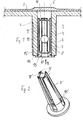
- the device consists of a holder 1, on which a Membrane 2 is arranged. From the device is in the figure only the middle part is shown. The holder 1 and the Membrane 2 are at their edges, not shown connected with each other. The type of connection can be in terms of on the innovation in any way, z. B. as it is in the DE 37 10 910 C2 is described to be executed.
- a pipe socket. 3 In the middle of the holder is with a pipe socket. 3 provided, which has an external thread 4. He can in one appropriately trained pipe a supply line for the air be screwed in and thus serves at the same time for feeding the air to the device as well as to hold the Contraption.
- the membrane 2 is provided with a plurality of fine slots (not shown). Only the middle, reinforced formed area 5 of the membrane, immediately above the Pipe socket 3 is located, is free of slots. About the slots can the prestressed air that the device over the Pipe socket 3 is fed into the surrounding water escape.
- a check valve 6 is arranged, which has a ball 8 which is located in a cage 7.
- the cage is cylindrical and has four webs 9 and one Floor 17 up. Air can enter the cage 8 via an opening 10 and thus flow into the pipe socket 3 and gaps 11th flow out again between the webs 9. The flow takes place in the direction of the arrow 12.
- the ball 8 is through the air does not raise and hinder the flow.
- the bottom 17 of the Cage 7 prevents the ball 8, the pipe socket. 3 leaves and between the diaphragm 2 and bracket 1 device.
- the cage 7 has a circumferential projection 13, whose diameter is larger than the inner diameter of the pipe socket 3, so that the cage is on the bottom 14 of the pipe socket 3 can support.
- the check valve 6 can thus between the pipe socket 3 and the end of the Supply line to which the device is connected, kept become.
- On the outer circumference of the cage 7 is a sealing ring 15th arranged.
- the cage 7 'shown in Fig. 2 differs from that shown in FIG. 1 in that it takes the form of a Truncated cone has. He has webs 9 ', a bottom 17' and a circumferential projection 13 'on.
- the cage 7 'can in Pipe socket with conical bore can be used. Of the Pipe socket can u. a. for manufacturing reasons, because of the better mold release, with a conical, downwardly expanding hole provided be. After a further training the innovation can with a conical design of cage 7 'and bore the circumferential projection 13 'omitted, since the cage in Upward direction, i. towards the membrane, against the hole can support.
Landscapes
- Chemical & Material Sciences (AREA)
- Chemical Kinetics & Catalysis (AREA)
- Engineering & Computer Science (AREA)
- General Engineering & Computer Science (AREA)
- Life Sciences & Earth Sciences (AREA)
- Hydrology & Water Resources (AREA)
- Environmental & Geological Engineering (AREA)
- Water Supply & Treatment (AREA)
- Organic Chemistry (AREA)
- Mechanical Engineering (AREA)
- Check Valves (AREA)
- Domestic Plumbing Installations (AREA)
Abstract
Description
- Fig. 1
- einen Querschnitt durch einen Teil einer Vorrichtung gemäß der Neuerung und
- Fig. 2
- einen Käfig für ein Rückschlagventil einer gegenüber Fig. 1 abgewandelten Vorrichtung.
Claims (6)
- Vorrichtung zum Belüften von Wasser mit einer starren, vorzugsweise im wesentlichen ebenen Halterung und einer darauf angeordneten, zum Austritt der Luft fein geschlitzten Membran aus Gummi oder einem gummiähnlichen Kunststoff, wobei die Halterung auf ihrer der Platte abgewandten Seite einen von der Platte überdeckten, als Rohrstutzen ausgebildeten Anschluss zum Zuführen der Luft aufweist, dadurch gekennzeichnet, dass in dem Rohrstutzen (3) ein Rückschlagventil (6) angeordnet ist, das einen in einem Käfig (7) gehaltenen, beweglichen, zum Verschließen des Rohrstutzens dienenden Körper, insb. eine Kugel (8) aufweist, wobei der Käfig (7) von der Membran (2) abgewandten Seite her in den Rohrstutzen (3) einsetzbar ist.
- Vorrichtung nach Anspruch 1, dadurch gekennzeichnet, dass der Käfig (7) an einem Ende einen umlaufenden Vorsprung (13) aufweist.
- Vorrichtung nach Anspruch 1, dadurch gekennzeichnet, dass der Käfig (7') eine konische Form hat.
- Vorrichtung nach Anspruch 2 und 3, dadurch gekennzeichnet, dass der umlaufende Vorsprung (13') an dem Ende des Käfigs, dass den größeren Durchmesser aufweist, angeordnet ist.
- Vorrichtung nach Anspruch 1, dadurch gekennzeichnet, dass der Käfig (7, 7') vier Stege (9, 9') aufweist.
- Vorrichtung nach Anspruch 1, dadurch gekennzeichnet, dass zwischen Rohrstutzen (3) und Käfig (7) eine Dichtung (15) angeordnet ist.
Applications Claiming Priority (2)
| Application Number | Priority Date | Filing Date | Title |
|---|---|---|---|
| DE20218719U | 2002-12-02 | ||
| DE20218719U DE20218719U1 (de) | 2002-12-02 | 2002-12-02 | Vorrichtung zum Belüften von Wasser |
Publications (1)
| Publication Number | Publication Date |
|---|---|
| EP1504807A1 true EP1504807A1 (de) | 2005-02-09 |
Family
ID=7977579
Family Applications (1)
| Application Number | Title | Priority Date | Filing Date |
|---|---|---|---|
| EP03027567A Withdrawn EP1504807A1 (de) | 2002-12-02 | 2003-12-01 | Vorrichtung zum Belüften von Wasser |
Country Status (2)
| Country | Link |
|---|---|
| EP (1) | EP1504807A1 (de) |
| DE (1) | DE20218719U1 (de) |
Families Citing this family (1)
| Publication number | Priority date | Publication date | Assignee | Title |
|---|---|---|---|---|
| CN105036309B (zh) * | 2015-08-31 | 2017-12-05 | 广东鑫都环保实业有限公司 | 一种无堵塞曝气系统用气水分离装置 |
Citations (7)
| Publication number | Priority date | Publication date | Assignee | Title |
|---|---|---|---|---|
| US3997634A (en) * | 1973-10-09 | 1976-12-14 | Downs Ernest W | Diffuser assembly |
| JPS57190697A (en) * | 1981-05-18 | 1982-11-24 | Serupoole Kogyo Kk | Air diffusion apparatus |
| US4764314A (en) * | 1984-03-21 | 1988-08-16 | Norbert Schneider | Diffuser for aeration basin |
| JPH03165897A (ja) * | 1989-11-24 | 1991-07-17 | Daicel Chem Ind Ltd | 散気装置 |
| DE4012631A1 (de) * | 1990-04-20 | 1991-10-24 | Karl Heinz Schuessler | Vorrichtung zum begasen von fluessigkeiten |
| JP2002013651A (ja) * | 2000-06-28 | 2002-01-18 | Tsutsunaka Sheet Bosui Kk | 散気装置用逆流防止弁 |
| US6367783B1 (en) * | 1998-06-23 | 2002-04-09 | Red Valve Company, Inc. | Fine bubble diffuser |
-
2002
- 2002-12-02 DE DE20218719U patent/DE20218719U1/de not_active Expired - Lifetime
-
2003
- 2003-12-01 EP EP03027567A patent/EP1504807A1/de not_active Withdrawn
Patent Citations (7)
| Publication number | Priority date | Publication date | Assignee | Title |
|---|---|---|---|---|
| US3997634A (en) * | 1973-10-09 | 1976-12-14 | Downs Ernest W | Diffuser assembly |
| JPS57190697A (en) * | 1981-05-18 | 1982-11-24 | Serupoole Kogyo Kk | Air diffusion apparatus |
| US4764314A (en) * | 1984-03-21 | 1988-08-16 | Norbert Schneider | Diffuser for aeration basin |
| JPH03165897A (ja) * | 1989-11-24 | 1991-07-17 | Daicel Chem Ind Ltd | 散気装置 |
| DE4012631A1 (de) * | 1990-04-20 | 1991-10-24 | Karl Heinz Schuessler | Vorrichtung zum begasen von fluessigkeiten |
| US6367783B1 (en) * | 1998-06-23 | 2002-04-09 | Red Valve Company, Inc. | Fine bubble diffuser |
| JP2002013651A (ja) * | 2000-06-28 | 2002-01-18 | Tsutsunaka Sheet Bosui Kk | 散気装置用逆流防止弁 |
Non-Patent Citations (3)
| Title |
|---|
| PATENT ABSTRACTS OF JAPAN vol. 007, no. 039 (C - 151) 17 February 1983 (1983-02-17) * |
| PATENT ABSTRACTS OF JAPAN vol. 015, no. 403 (C - 0875) 15 October 1991 (1991-10-15) * |
| PATENT ABSTRACTS OF JAPAN vol. 2002, no. 05 3 May 2002 (2002-05-03) * |
Also Published As
| Publication number | Publication date |
|---|---|
| DE20218719U1 (de) | 2003-02-27 |
Similar Documents
| Publication | Publication Date | Title |
|---|---|---|
| EP0174429B1 (de) | Vorrichtung zur Belüftung von Abwasser oder dgl. Medien in Belüftungsbecken | |
| EP0345207B1 (de) | Begasungseinrichtung | |
| DE4001201C1 (de) | ||
| EP1366807A2 (de) | Vorrichtung zum Belüften von Wasser | |
| WO2008009484A2 (de) | Belüfter | |
| DE3441731A1 (de) | Belueftungselement | |
| DE2035651A1 (de) | Einrichtung zum feinblasigen Belüften von Flüssigkeiten, insbesondere Abwasser und Verfahren zum Betrieb der Einrichtung | |
| DE2261994A1 (de) | Einrichtung zum feinblasigen belueften von abwasser | |
| EP3570966B1 (de) | Belüftungselement | |
| EP1504807A1 (de) | Vorrichtung zum Belüften von Wasser | |
| DE202015106563U1 (de) | Perforierter Membranbelüfter | |
| EP2374527B1 (de) | Begasungseinrichtung zum intermittierenden Einbringen eines Gases in eine Flüssigkeit | |
| DE2453670A1 (de) | Einrichtung zum verteilen von gasen in fluessigkeiten | |
| DE102009060185A1 (de) | Membran-Rohrbelüfter | |
| DE4223942A1 (de) | Schlauchbelüfter | |
| EP3885638A1 (de) | Gasspeicher | |
| DE3834317C1 (en) | Apparatus for introducing gas into a liquid | |
| DE102009041992A1 (de) | Vorrichtung zum Begasen/Belüften von Flüssigkeiten | |
| DE9013213U1 (de) | Membrane für einen Flächenbegaser und Flächenbegaser | |
| DE2233210B2 (de) | Druckregler fuer druckluftbremsanlagen | |
| DE102010015059B4 (de) | Begasungseinrichtung zum Einbringen eines Gases in eine Flüssigkeit | |
| DE102008029273B4 (de) | Vorrichtung zum Begasen einer Flüssigkeit, insbesondere zum Belüften von Abwasser, sowie Klärbecken | |
| DE3528555A1 (de) | Vorrichtung zum verhindern der verstopfung einer luftdiffusorroehre | |
| DE3410186A1 (de) | Fluessigkeitsmengenregler mit rueckschlagventil | |
| DE102006056129A1 (de) | Vorrichtung und Verfahren zur Verminderung von Geruchsbelästigung bei Fahrzeugwaschanlagen |
Legal Events
| Date | Code | Title | Description |
|---|---|---|---|
| PUAI | Public reference made under article 153(3) epc to a published international application that has entered the european phase |
Free format text: ORIGINAL CODE: 0009012 |
|
| AK | Designated contracting states |
Kind code of ref document: A1 Designated state(s): AT BE BG CH CY CZ DE DK EE ES FI FR GB GR HU IE IT LI LU MC NL PT RO SE SI SK TR |
|
| AX | Request for extension of the european patent |
Extension state: AL LT LV MK |
|
| RIN1 | Information on inventor provided before grant (corrected) |
Inventor name: DRAGEL, THOMAS |
|
| AKX | Designation fees paid |
Designated state(s): AT BE BG CH CY CZ DE DK EE ES FI FR GB GR HU IE IT LI LU MC NL PT RO SE SI SK TR |
|
| STAA | Information on the status of an ep patent application or granted ep patent |
Free format text: STATUS: THE APPLICATION IS DEEMED TO BE WITHDRAWN |
|
| 18D | Application deemed to be withdrawn |
Effective date: 20050810 |