EP1504637B1 - Retaining and heat dissipating structure for electronic equipment - Google Patents
Retaining and heat dissipating structure for electronic equipment Download PDFInfo
- Publication number
- EP1504637B1 EP1504637B1 EP03719037A EP03719037A EP1504637B1 EP 1504637 B1 EP1504637 B1 EP 1504637B1 EP 03719037 A EP03719037 A EP 03719037A EP 03719037 A EP03719037 A EP 03719037A EP 1504637 B1 EP1504637 B1 EP 1504637B1
- Authority
- EP
- European Patent Office
- Prior art keywords
- retaining
- heat dissipating
- dissipating structure
- container
- ceramic powder
- Prior art date
- Legal status (The legal status is an assumption and is not a legal conclusion. Google has not performed a legal analysis and makes no representation as to the accuracy of the status listed.)
- Expired - Lifetime
Links
- 239000000843 powder Substances 0.000 claims abstract description 51
- 239000000919 ceramic Substances 0.000 claims abstract description 33
- 239000000463 material Substances 0.000 claims abstract description 19
- 230000017525 heat dissipation Effects 0.000 claims description 12
- 239000000945 filler Substances 0.000 claims description 11
- 239000003973 paint Substances 0.000 claims description 10
- 238000005192 partition Methods 0.000 claims description 6
- QYEXBYZXHDUPRC-UHFFFAOYSA-N B#[Ti]#B Chemical compound B#[Ti]#B QYEXBYZXHDUPRC-UHFFFAOYSA-N 0.000 claims description 4
- 229910052581 Si3N4 Inorganic materials 0.000 claims description 4
- 229910033181 TiB2 Inorganic materials 0.000 claims description 4
- HQVNEWCFYHHQES-UHFFFAOYSA-N silicon nitride Chemical compound N12[Si]34N5[Si]62N3[Si]51N64 HQVNEWCFYHHQES-UHFFFAOYSA-N 0.000 claims description 4
- 239000011248 coating agent Substances 0.000 claims description 3
- 238000000576 coating method Methods 0.000 claims description 3
- PIGFYZPCRLYGLF-UHFFFAOYSA-N Aluminum nitride Chemical compound [Al]#N PIGFYZPCRLYGLF-UHFFFAOYSA-N 0.000 claims description 2
- LTPBRCUWZOMYOC-UHFFFAOYSA-N Beryllium oxide Chemical compound O=[Be] LTPBRCUWZOMYOC-UHFFFAOYSA-N 0.000 claims description 2
- PZNSFCLAULLKQX-UHFFFAOYSA-N Boron nitride Chemical compound N#B PZNSFCLAULLKQX-UHFFFAOYSA-N 0.000 claims description 2
- 239000011810 insulating material Substances 0.000 claims description 2
- TWNQGVIAIRXVLR-UHFFFAOYSA-N oxo(oxoalumanyloxy)alumane Chemical compound O=[Al]O[Al]=O TWNQGVIAIRXVLR-UHFFFAOYSA-N 0.000 claims description 2
- HBMJWWWQQXIZIP-UHFFFAOYSA-N silicon carbide Chemical compound [Si+]#[C-] HBMJWWWQQXIZIP-UHFFFAOYSA-N 0.000 claims description 2
- RCKBMGHMPOIFND-UHFFFAOYSA-N sulfanylidene(sulfanylidenegallanylsulfanyl)gallane Chemical compound S=[Ga]S[Ga]=S RCKBMGHMPOIFND-UHFFFAOYSA-N 0.000 claims description 2
- 239000000203 mixture Substances 0.000 claims 1
- 230000006835 compression Effects 0.000 abstract 1
- 238000007906 compression Methods 0.000 abstract 1
- 229910052751 metal Inorganic materials 0.000 description 6
- 239000002184 metal Substances 0.000 description 6
- 230000001133 acceleration Effects 0.000 description 5
- 230000003321 amplification Effects 0.000 description 4
- 239000010410 layer Substances 0.000 description 4
- 238000003199 nucleic acid amplification method Methods 0.000 description 4
- 230000009471 action Effects 0.000 description 3
- 230000000930 thermomechanical effect Effects 0.000 description 3
- 210000002268 wool Anatomy 0.000 description 3
- 238000005299 abrasion Methods 0.000 description 2
- 230000008901 benefit Effects 0.000 description 2
- 238000011161 development Methods 0.000 description 2
- 238000010292 electrical insulation Methods 0.000 description 2
- 230000008030 elimination Effects 0.000 description 2
- 238000003379 elimination reaction Methods 0.000 description 2
- 230000006872 improvement Effects 0.000 description 2
- 239000007788 liquid Substances 0.000 description 2
- 229920001296 polysiloxane Polymers 0.000 description 2
- 238000007789 sealing Methods 0.000 description 2
- 125000006850 spacer group Chemical group 0.000 description 2
- RYGMFSIKBFXOCR-UHFFFAOYSA-N Copper Chemical compound [Cu] RYGMFSIKBFXOCR-UHFFFAOYSA-N 0.000 description 1
- 239000004593 Epoxy Substances 0.000 description 1
- 230000002528 anti-freeze Effects 0.000 description 1
- 239000011230 binding agent Substances 0.000 description 1
- JJWKPURADFRFRB-UHFFFAOYSA-N carbonyl sulfide Chemical compound O=C=S JJWKPURADFRFRB-UHFFFAOYSA-N 0.000 description 1
- 229910052802 copper Inorganic materials 0.000 description 1
- 239000010949 copper Substances 0.000 description 1
- 238000013461 design Methods 0.000 description 1
- 238000006073 displacement reaction Methods 0.000 description 1
- 230000000694 effects Effects 0.000 description 1
- 239000013536 elastomeric material Substances 0.000 description 1
- 230000005484 gravity Effects 0.000 description 1
- 238000010438 heat treatment Methods 0.000 description 1
- 230000036039 immunity Effects 0.000 description 1
- 238000003780 insertion Methods 0.000 description 1
- 230000037431 insertion Effects 0.000 description 1
- 238000004519 manufacturing process Methods 0.000 description 1
- 230000005226 mechanical processes and functions Effects 0.000 description 1
- 238000012986 modification Methods 0.000 description 1
- 230000004048 modification Effects 0.000 description 1
- 238000013021 overheating Methods 0.000 description 1
- 229920000647 polyepoxide Polymers 0.000 description 1
- 229920000642 polymer Polymers 0.000 description 1
- 239000011148 porous material Substances 0.000 description 1
- 238000009702 powder compression Methods 0.000 description 1
- 230000005855 radiation Effects 0.000 description 1
- 230000009467 reduction Effects 0.000 description 1
- 229920005989 resin Polymers 0.000 description 1
- 239000011347 resin Substances 0.000 description 1
- 229920002050 silicone resin Polymers 0.000 description 1
- 230000003068 static effect Effects 0.000 description 1
- 238000005728 strengthening Methods 0.000 description 1
- 239000002344 surface layer Substances 0.000 description 1
- 229920002803 thermoplastic polyurethane Polymers 0.000 description 1
Images



Classifications
-
- H—ELECTRICITY
- H05—ELECTRIC TECHNIQUES NOT OTHERWISE PROVIDED FOR
- H05K—PRINTED CIRCUITS; CASINGS OR CONSTRUCTIONAL DETAILS OF ELECTRIC APPARATUS; MANUFACTURE OF ASSEMBLAGES OF ELECTRICAL COMPONENTS
- H05K7/00—Constructional details common to different types of electric apparatus
- H05K7/20—Modifications to facilitate cooling, ventilating, or heating
- H05K7/2039—Modifications to facilitate cooling, ventilating, or heating characterised by the heat transfer by conduction from the heat generating element to a dissipating body
- H05K7/20436—Inner thermal coupling elements in heat dissipating housings, e.g. protrusions or depressions integrally formed in the housing
- H05K7/20445—Inner thermal coupling elements in heat dissipating housings, e.g. protrusions or depressions integrally formed in the housing the coupling element being an additional piece, e.g. thermal standoff
- H05K7/20463—Filling compound, e.g. potted resin
Definitions
- the present invention relates to a retaining and heat dissipating structure for electronic equipment, in particular electronic equipment installed aboard space, air or land vehicles.
- the inside of space vehicles is generally occupied by a multiplicity of containers or boxes forming the external envelopes of electronic devices required for vehicle operation (subsystem load) or for performing the functions the vehicle has been designed for (payload).
- the devices internally consist of a number of analogue or digital printed circuit boards, which are mutually adjacent and carry the electronic components, possibly connected to a motherboard.
- the devices are generally mutually connected through electrical connectors or wirings that come out from the containers and that are connected to the printed circuit boards inside the devices.
- Each device has, inside the space vehicle, a pre-set fixed position, defined by a number of constraints such as the container size, heat dissipation, the centre of gravity, stiffness, immunity from electromagnetic interference.
- the above solution has some drawbacks. First, it considerably adds to the electronic equipment mass, due to the use of thermally conductive powders in admixture with a polymerising silicone resin, which together have a density that only seldom is below 1 g/cm 3 . Moreover, once the filler is hardened, it is no longer capable of absorbing mechanical vibrations. Further, the presence of the hardened material makes replacement of equipment parts in case of failure very difficult or even impossible.
- EP 1 041 002 A discloses a retaining and heat dissipating structure using elements of polymeric material that bear a coating of metal or metal fibres (metal wool) and are placed between the printed circuit boards inside a container for an electronic device and, if necessary, between the container and the external walls of a plurality of other devices contained therein.
- metal or metal fibres metal wool
- the boards are to be treated to maintain electrical insulation and, in case of the metal wool, to prevent abrasion.
- EP 0 951 207 A discloses a retaining and heat dissipating structure using a lightweight loose material, with shock-absorbing properties, and a pressurised antifreeze and heat conducting liquid, arranged within a container housing elements forming the equipment.
- the system can be used for equipment in which said elements (generally, closed casings containing a plurality of boards) are suspended in the container so as to have a certain freedom of movement.
- said elements generally, closed casings containing a plurality of boards
- the above solution has the drawback of requiring a tightly sealed container to prevent liquid leakage, with a consequent cost increase.
- the invention concerns a retaining and heat dissipating structure, which does not have the drawbacks of the prior art.
- a first object of the invention is to provide a retaining and heat dissipating structure in which the thermo-mechanical performance of the system vehicle - on board equipment is enhanced, thereby reducing the design effort, and hence the development costs, required to meet the specifications concerning load resistance and heat dissipation.
- Another object of the invention is to provide a retaining and heat dissipating structure allowing decoupling, from the mechanical standpoint, the elements forming the equipment (printed circuit boards and/or housing containers) from higher level structures: thus, the mass is reduced thanks to the elimination of mechanical connecting parts and, moreover, the manufacture is made simpler and the flexibility in arranging the individual parts within the containers and aboard the vehicle is increased.
- a further object of the invention is to provide a retaining and heat dissipating structure in which the mechanical load factors are reduced, whereby containers with thinner wall can be used, thus allowing a further mass reduction.
- the retaining and heat dissipating structure comprising at least a container housing elements forming the equipment and a filler for the container filling the space around such elements, wherein said filler comprises a ceramic powder in loose condition.
- ceramic powders have excellent dielectric and heat conducting properties and are commonly used in electronics, together with binders such as epoxy or urethane resins, silicones and other polymers, to improve conductivity of electrical components and to reduce the thermal expansion thereof, while maintaining electrical insulation.
- binders such as epoxy or urethane resins, silicones and other polymers
- the invention also provides an air, space or land vehicle carrying electronic equipment arranged within one or more containers, wherein such equipment is associated with a retaining and heat dissipating structure utilising a ceramic powder placed within the or each container, and between containers carried by a common closed casing.
- an electronic equipment comprises a plurality of analogue and/or digital printed circuit boards 1 carrying a plurality of electronic components 2.
- the whole equipment is housed in a container or casing 3, suitable for being located aboard a satellite or other space, air or land vehicle.
- boards 1 can be connected to a motherboard 5 through connectors 4, as shown in the drawings, or they can be independent of one another.
- Other connectors 6, coming out from container 3, allow connecting the equipment to other equipment carried by the vehicle.
- boards 1 are not rigidly secured to container 3, but they are free, apart from the connection formed by motherboard 5, if any, and connector 6 fastened to the container wall.
- Motherboard 5 may be supported by suitable spacers 12, of rigid or elastomeric material, which keep the motherboard in a desired position and make insertion of boards connected thereto easier.
- the mechanical constraint consisting only of connectors 6 secured to the wall and of motherboard 5 more or less rigidly secured to container 3 would not be enough without intervention of another rigid mechanical support.
- the latter is obtained by introducing a ceramic powder 7 into container 3, into the gaps between boards 1 and motherboard 5, the powder being introduced in such an amount that it is submitted to a certain pressure that may be in the range from some millibars to about ten bars, e.g. 4 bar, in order not to impose an excessive weight penalty onto container 3.
- Powder compression is the necessary and sufficient condition to create a mechanical stiffness for boards 1 and motherboard 5.
- the size of the grains of ceramic powder 7 is preferably between about 0.1 ⁇ m and about 500 ⁇ m.
- Ceramic powders suitable for the above purpose are for instance powders of: boron nitride (BN), aluminium nitride (AlN), aluminium oxide (Al 2 O 3 ), beryllium oxide (BeO), silicon carbide (SiC), silicon nitride (Si 3 N 4 ), titanium diboride (TiB 2 ), zirconium diboride (ZrB 2 ).
- BN boron nitride
- AlN aluminium nitride
- Al 2 O 3 aluminium oxide
- BeO beryllium oxide
- SiC silicon carbide
- Si 3 N 4 silicon nitride
- TiB 2 titanium diboride
- ZrB 2 zirconium diboride
- Ceramic powder 7 under the condition of use according to the invention, becomes a substantially uncompressible material that no longer can move under the action of the static and dynamic loads, which the equipment and its container undergo during vehicle movements. In effect, notwithstanding the reduced size, the grains, once compressed in a pre-set space, can move only if submitted to very high energies.
- Ceramic powders have excellent dielectric and heat conducting properties and they do not cause abrasion of the electronic parts or of the wirings. Moreover the powders, being used alone and not together with resins to be polymerised to exert a mechanic restraint action, allow access to boards 1 for replacement in case of failure.
- the presence of the filler also increases protection against cosmic radiation.
- powder 7 can be mixed with a lighter material, consisting of hollow elements 8 (e.g. balls, cuboids and the like) of rigid or flexible polymeric material. It is to be appreciated that elements 8 have no load resistance tasks, but they only are to reduce the overall mass.
- elements 8 e.g. balls, cuboids and the like
- Powder 7 and lightening elements 8 may be introduced through a removable cover of container 3 or, as shown in the drawing, through a loading valve 9.
- a control valve 10 allows controlling filling operation and exhausting air.
- a filter or porous partition can be provided to let out residual air in a controlled time once the vehicle is in the empty space.
- the size of the partition pores will be smaller than the minimum size of the powder grains.
- container 3 it is possible to create a vacuum inside container 3 once the powder has been introduced and compressed. In such case a partition to let out air will not be necessary, but container 3 should be made as airtight as possible.
- the advantage of this solution is that the system is made even more rigid and that the walls of container 3 can be made very light, the overall container stiffness being ensured by the negative pressure differential with respect to the outside pressure.
- the surface of the powder in loose condition contained within container 3, once the powder has been compressed, is coated with a suitable paint which, once dried, forms a layer S sealing container 3.
- the paint actually penetrates into the space normally occupied by the air between the powder grains, forming a hard surface layer S or crust.
- Suitable paints for that purpose are for instance paints in the group known as "conformal coating", which are used as insulating materials for electrical protection of electronic boards.
- Such paints can advantageously be sprayed onto the surface of the powder in the container so as to obtain a layer S with a thickness of some millimetres, preferably about 10 mm, sealing the powder.
- the paint deposited onto the mass of ceramic powder could also penetrate deeply so as to fill substantially the whole space between the powder grains in container 3.
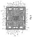
- FIG. 3 shows the application of the invention to a complex system comprising a plurality of devices like that shown in Figs. 1 and 2. Elements already disclosed in Figs. 1 and 2 are denoted by the same reference numerals. For sake of simplicity of the drawing, neither the connectors/wirings for connecting the different devices, nor the motherboards, if any, inside the devices are shown.
- Each device comprising the plurality of printed circuit boards 1 with electronic components 2, is therefore mounted in a respective container 3 filled with ceramic powder 7 possibly mixed with lightening material 8.
- Containers 3 are located inside a box or common closed casing 15 and are mechanically decoupled therefrom. The space between containers 3 and the internal walls of box 15 is then wholly filled with the compressed ceramic powder, with the possible addition of lightening material 8.
- ceramic powder 7 forms the only means for mechanical restraint and heat dissipation for the whole structure and its parts.
- advantages in terms of thermo-mechanical performance, described above with reference to a single device, are thus achieved also in case of a complex equipment.
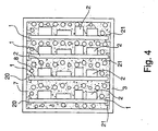
- Fig. 4 shows the use of the present invention in a traditional equipment with a conventional mechanical structure, in which boards 1 are rigidly mounted, through securing means, not shown, in guides 20, 21 secured to the upper and lower walls of container 3.
- the space between boards 1 is still filled with ceramic powder 7, possibly mixed with lightening material 8.
- the motherboard if any, the connectors, valves 9 and 10 and partition 11 are not shown.
- the filler has a secondary mechanical function in reducing amplification, the primary function being performed by container 3 and guides 20, 21, as well as a primary function in improving heat dissipation of the equipment.
- the improvement is of course paid for with some increase in the equipment mass.
- the solution shown in Fig. 4 may also be used to create a redundancy in the thermo-mechanical characteristics (restraint and dissipation) of a conventional equipment (thus equipped with heat dissipating elements associated with container 3 and distinct from ceramic powder 7).
- a failure with consequent development of a high thermal power, the equipment can continue operating, even though with reduced performance, thanks to the action of ceramic powder 7.
- Such a solution is of interest when the mass is not a particularly critical factor, whereas ensuring a high operation reliability is essential.
- Fig. 4 can be extended to complex structures, in which containers 3 of the individual devices are secured to a box like box 15 in Fig. 3, possibly equipped with heat dissipating means distinct from the ceramic powder.
Landscapes
- Physics & Mathematics (AREA)
- Thermal Sciences (AREA)
- Engineering & Computer Science (AREA)
- Microelectronics & Electronic Packaging (AREA)
- Cooling Or The Like Of Electrical Apparatus (AREA)
- Casings For Electric Apparatus (AREA)
- Cable Accessories (AREA)
Applications Claiming Priority (3)
| Application Number | Priority Date | Filing Date | Title |
|---|---|---|---|
| ITTO20020416 | 2002-05-16 | ||
| IT2002TO000416A ITTO20020416A1 (it) | 2002-05-16 | 2002-05-16 | Struttura di contenimento e dissipazione termica per apparecchiature elettroniche. |
| PCT/IB2003/001873 WO2003098987A1 (en) | 2002-05-16 | 2003-05-07 | Retaining and heat dissipating structure for electronic equipment |
Publications (2)
| Publication Number | Publication Date |
|---|---|
| EP1504637A1 EP1504637A1 (en) | 2005-02-09 |
| EP1504637B1 true EP1504637B1 (en) | 2006-10-04 |
Family
ID=27639084
Family Applications (1)
| Application Number | Title | Priority Date | Filing Date |
|---|---|---|---|
| EP03719037A Expired - Lifetime EP1504637B1 (en) | 2002-05-16 | 2003-05-07 | Retaining and heat dissipating structure for electronic equipment |
Country Status (8)
| Country | Link |
|---|---|
| US (1) | US7099157B2 (it) |
| EP (1) | EP1504637B1 (it) |
| CN (1) | CN100431398C (it) |
| AT (1) | ATE341926T1 (it) |
| AU (1) | AU2003223066A1 (it) |
| DE (1) | DE60302785T2 (it) |
| IT (1) | ITTO20020416A1 (it) |
| WO (1) | WO2003098987A1 (it) |
Cited By (1)
| Publication number | Priority date | Publication date | Assignee | Title |
|---|---|---|---|---|
| DE102010016288A1 (de) * | 2010-04-01 | 2011-10-06 | Jena-Optronik Gmbh | Elektronische Baueinheit und Weltraumfahrzeug damit |
Families Citing this family (11)
| Publication number | Priority date | Publication date | Assignee | Title |
|---|---|---|---|---|
| US7843689B2 (en) * | 2005-04-22 | 2010-11-30 | Robby Jay Moore | Fire resistant and water resistant enclosure for operable computer digital data storage device |
| KR100677620B1 (ko) * | 2005-11-22 | 2007-02-02 | 삼성전자주식회사 | 전자기기의 냉각 방법 및 냉각 효율이 향상된 전자기기 |
| CN101018472A (zh) * | 2007-02-18 | 2007-08-15 | 华为技术有限公司 | 一种电子设备及其装配方法 |
| US8360390B2 (en) * | 2009-01-13 | 2013-01-29 | Enphase Energy, Inc. | Method and apparatus for potting an electronic device |
| US8419385B2 (en) * | 2009-06-15 | 2013-04-16 | Sunonwealth Electric Machine Industry Co., Ltd. | Heat-dissipating fan |
| JP2011176096A (ja) * | 2010-02-24 | 2011-09-08 | Mitsumi Electric Co Ltd | 電子機器 |
| CN102223781A (zh) * | 2010-04-16 | 2011-10-19 | 华广光电股份有限公司 | 积层式复合导散热构造 |
| WO2016121660A1 (ja) * | 2015-01-29 | 2016-08-04 | 京セラ株式会社 | 回路基板および電子装置 |
| EP3565395B1 (en) * | 2016-12-28 | 2022-03-16 | Mitsubishi Electric Corporation | Power supply device |
| CN109693812A (zh) * | 2017-10-23 | 2019-04-30 | 中国科学院空间应用工程与技术中心 | 一种用于为多个空间实验设备提供实验服务的系统及方法 |
| EP3817529B1 (en) | 2018-06-27 | 2023-10-04 | Mitsubishi Electric Corporation | Power supply device |
Family Cites Families (14)
| Publication number | Priority date | Publication date | Assignee | Title |
|---|---|---|---|---|
| US3888691A (en) * | 1972-10-06 | 1975-06-10 | Lockheed Aircraft Corp | Porous ceramic |
| US5420085A (en) * | 1985-02-04 | 1995-05-30 | Lanxide Technology Company, Lp | Methods of making composite aluminum nitride ceramic articles having embedded filler |
| US5060114A (en) | 1990-06-06 | 1991-10-22 | Zenith Electronics Corporation | Conformable pad with thermally conductive additive for heat dissipation |
| US5307508A (en) * | 1991-05-13 | 1994-04-26 | Motorola, Inc. | Shock isolation for selective call receivers |
| CN2135871Y (zh) * | 1992-01-09 | 1993-06-09 | 王刚 | 大功率直流/直流变换电源器件 |
| CA2120468A1 (en) * | 1993-04-05 | 1994-10-06 | Kenneth Alan Salisbury | Electronic module containing an internally ribbed, integral heat sink and bonded, flexible printed wiring board with two-sided component population |
| US5756934A (en) * | 1994-10-11 | 1998-05-26 | Loral Fairchild Corp. | Flight crash survivable storage unit with aquarium container for flight recorder memory |
| US5932839A (en) * | 1997-11-04 | 1999-08-03 | Ren; Jane | Method for dissipating heat away from a heat sensitive device using bicarbonate compositions |
| DE69800442T2 (de) | 1998-03-23 | 2001-07-12 | Negesat Di Boer Fabrizio & C S | Schutzgehäuse für Anwendungen in der Raumfahrt |
| US6013592A (en) | 1998-03-27 | 2000-01-11 | Siemens Westinghouse Power Corporation | High temperature insulation for ceramic matrix composites |
| IT1308435B1 (it) | 1999-04-01 | 2001-12-17 | Negesat Di Boer Fabrizio & C S | Struttura di contenimento e dissipazione termica per equipaggiamentiin un veicolo aeronautico o spaziale |
| EP0992430A3 (en) * | 1998-10-07 | 2000-09-13 | Negesat Di Boer Fabrizio & C. SNC | Housing providing cooling for equipment aboard aircraft or spacecraft |
| US6549409B1 (en) * | 2000-08-21 | 2003-04-15 | Vlt Corporation | Power converter assembly |
| DE10130592C1 (de) * | 2001-06-27 | 2002-10-24 | Infineon Technologies Ag | Modulbaugruppe für Speicher-Module und Verfahren zu ihrer Herstellung |
-
2002
- 2002-05-16 IT IT2002TO000416A patent/ITTO20020416A1/it unknown
-
2003
- 2003-05-07 US US10/512,854 patent/US7099157B2/en not_active Expired - Fee Related
- 2003-05-07 CN CNB038140055A patent/CN100431398C/zh not_active Expired - Fee Related
- 2003-05-07 EP EP03719037A patent/EP1504637B1/en not_active Expired - Lifetime
- 2003-05-07 DE DE60302785T patent/DE60302785T2/de not_active Expired - Lifetime
- 2003-05-07 WO PCT/IB2003/001873 patent/WO2003098987A1/en not_active Ceased
- 2003-05-07 AT AT03719037T patent/ATE341926T1/de not_active IP Right Cessation
- 2003-05-07 AU AU2003223066A patent/AU2003223066A1/en not_active Abandoned
Cited By (2)
| Publication number | Priority date | Publication date | Assignee | Title |
|---|---|---|---|---|
| DE102010016288A1 (de) * | 2010-04-01 | 2011-10-06 | Jena-Optronik Gmbh | Elektronische Baueinheit und Weltraumfahrzeug damit |
| DE102010016288B4 (de) * | 2010-04-01 | 2011-12-15 | Jena-Optronik Gmbh | Elektronische Baueinheit und Weltraumfahrzeug damit |
Also Published As
| Publication number | Publication date |
|---|---|
| WO2003098987A1 (en) | 2003-11-27 |
| US7099157B2 (en) | 2006-08-29 |
| DE60302785T2 (de) | 2007-03-15 |
| CN100431398C (zh) | 2008-11-05 |
| US20060133045A1 (en) | 2006-06-22 |
| ITTO20020416A0 (it) | 2002-05-16 |
| AU2003223066A8 (en) | 2003-12-02 |
| ATE341926T1 (de) | 2006-10-15 |
| AU2003223066A1 (en) | 2003-12-02 |
| EP1504637A1 (en) | 2005-02-09 |
| CN1717966A (zh) | 2006-01-04 |
| DE60302785D1 (de) | 2006-01-19 |
| ITTO20020416A1 (it) | 2003-11-17 |
Similar Documents
| Publication | Publication Date | Title |
|---|---|---|
| EP1504637B1 (en) | Retaining and heat dissipating structure for electronic equipment | |
| US7095615B2 (en) | Environmentally tuned circuit card assembly and method for manufacturing the same | |
| US6614108B1 (en) | Electronic package and method therefor | |
| US6944022B1 (en) | Ruggedized electronics enclosure | |
| US20070041160A1 (en) | Thermal management for a ruggedized electronics enclosure | |
| US5143790A (en) | Integrally-damped steel composite laminated structure and method of attaching same | |
| US6215658B1 (en) | Structure for housing and heat sinking equipment pieces in an aeronautic or space vehicle | |
| RU2374148C2 (ru) | Модульная конструкция космического аппарата | |
| CN111971810A (zh) | 多件式多功能电池壳 | |
| Jang et al. | Development of multi-functional composite structures with embedded electronics for space application | |
| CN109065081B (zh) | 一种抗大过载冲击的存储装置及其制备方法 | |
| EP1041002A2 (en) | Protective casing with cooling for equipment in air, space or land vehicles | |
| CN101142865A (zh) | 用于电子设备的轻质刚性箱体 | |
| US8404979B2 (en) | Composite multilayer wiring board | |
| GB2591130A (en) | Space system container | |
| EP0951207B1 (en) | Protective housing for space applications | |
| WO2023036616A1 (en) | Integration of systems comprising standard electronic components in satellites | |
| CN116592088B (zh) | 一种控制装置的防振方法 | |
| US7380380B2 (en) | Thermal protection device | |
| WO2026050234A1 (en) | Radiation shielding material using a boron carbide epoxy and method for spaceborne applications | |
| WO1998036628A9 (en) | Apparatus and method of protecting electronics | |
| WO1998036628A1 (en) | Apparatus and method of protecting electronics | |
| JP3038602U (ja) | 宇宙耐環境性コンテナ装置 | |
| Jang et al. | Development of lightweight multi-functional structures with embedded electronics for space application | |
| Atxaga et al. | Multifunctional structures using high thermal conductivity fibres |
Legal Events
| Date | Code | Title | Description |
|---|---|---|---|
| PUAI | Public reference made under article 153(3) epc to a published international application that has entered the european phase |
Free format text: ORIGINAL CODE: 0009012 |
|
| 17P | Request for examination filed |
Effective date: 20041111 |
|
| AK | Designated contracting states |
Kind code of ref document: A1 Designated state(s): AT BE BG CH CY CZ DE DK EE ES FI FR GB GR HU IE IT LI LU MC NL PT RO SE SI SK TR |
|
| AX | Request for extension of the european patent |
Extension state: AL LT LV MK |
|
| GRAP | Despatch of communication of intention to grant a patent |
Free format text: ORIGINAL CODE: EPIDOSNIGR1 |
|
| DAX | Request for extension of the european patent (deleted) | ||
| GRAS | Grant fee paid |
Free format text: ORIGINAL CODE: EPIDOSNIGR3 |
|
| GRAA | (expected) grant |
Free format text: ORIGINAL CODE: 0009210 |
|
| RAP1 | Party data changed (applicant data changed or rights of an application transferred) |
Owner name: ARTHE ENGINEERING SOLUTIONS S.R.L. Owner name: FINMECCANICA S.P.A. |
|
| AK | Designated contracting states |
Kind code of ref document: B1 Designated state(s): AT BE BG CH CY CZ DE DK EE ES FI FR GB GR HU IE IT LI LU MC NL PT RO SE SI SK TR |
|
| REG | Reference to a national code |
Ref country code: GB Ref legal event code: FG4D |
|
| REG | Reference to a national code |
Ref country code: CH Ref legal event code: EP |
|
| REG | Reference to a national code |
Ref country code: IE Ref legal event code: FG4D |
|
| REF | Corresponds to: |
Ref document number: 60302785 Country of ref document: DE Date of ref document: 20060119 Kind code of ref document: P |
|
| PUAC | Information related to the publication of a b1 document modified or deleted |
Free format text: ORIGINAL CODE: 0009299EPPU |
|
| REG | Reference to a national code |
Ref country code: CH Ref legal event code: PK Free format text: BERICHTIGUNG |
|
| DB1 | Publication of patent cancelled | ||
| NLV1 | Nl: lapsed or annulled due to failure to fulfill the requirements of art. 29p and 29m of the patents act | ||
| REG | Reference to a national code |
Ref country code: GB Ref legal event code: ERR Free format text: THE GRANT DATE WAS DELETED BY THE EPO IN EUROPEAN PATENT BULLETIN 2006/20 DATED 20060517 |
|
| NLXE | Nl: other communications concerning ep-patents (part 3 heading xe) |
Free format text: PAT. BUL. 02/2006: PATENTNUMBER 1504637 SHOULD BE DELETED (SEE EUROPEAN PATENT BULLETIN 20060517) |
|
| ET | Fr: translation filed | ||
| GRAA | (expected) grant |
Free format text: ORIGINAL CODE: 0009210 |
|
| AK | Designated contracting states |
Kind code of ref document: B1 Designated state(s): AT BE BG CH CY CZ DE DK EE ES FI FR GB GR HU IE IT LI LU MC NL PT RO SE SI SK TR |
|
| PG25 | Lapsed in a contracting state [announced via postgrant information from national office to epo] |
Ref country code: LI Free format text: LAPSE BECAUSE OF FAILURE TO SUBMIT A TRANSLATION OF THE DESCRIPTION OR TO PAY THE FEE WITHIN THE PRESCRIBED TIME-LIMIT Effective date: 20061004 Ref country code: NL Free format text: LAPSE BECAUSE OF FAILURE TO SUBMIT A TRANSLATION OF THE DESCRIPTION OR TO PAY THE FEE WITHIN THE PRESCRIBED TIME-LIMIT Effective date: 20061004 Ref country code: CZ Free format text: LAPSE BECAUSE OF FAILURE TO SUBMIT A TRANSLATION OF THE DESCRIPTION OR TO PAY THE FEE WITHIN THE PRESCRIBED TIME-LIMIT Effective date: 20061004 Ref country code: CH Free format text: LAPSE BECAUSE OF FAILURE TO SUBMIT A TRANSLATION OF THE DESCRIPTION OR TO PAY THE FEE WITHIN THE PRESCRIBED TIME-LIMIT Effective date: 20061004 Ref country code: AT Free format text: LAPSE BECAUSE OF FAILURE TO SUBMIT A TRANSLATION OF THE DESCRIPTION OR TO PAY THE FEE WITHIN THE PRESCRIBED TIME-LIMIT Effective date: 20061004 |
|
| REG | Reference to a national code |
Ref country code: GB Ref legal event code: FG4D |
|
| REG | Reference to a national code |
Ref country code: CH Ref legal event code: EP |
|
| PG25 | Lapsed in a contracting state [announced via postgrant information from national office to epo] |
Ref country code: DK Free format text: LAPSE BECAUSE OF NON-PAYMENT OF DUE FEES Effective date: 20070104 |
|
| REF | Corresponds to: |
Ref document number: 60302785 Country of ref document: DE Date of ref document: 20070104 Kind code of ref document: P |
|
| ET | Fr: translation filed | ||
| NLV1 | Nl: lapsed or annulled due to failure to fulfill the requirements of art. 29p and 29m of the patents act | ||
| REG | Reference to a national code |
Ref country code: CH Ref legal event code: PL |
|
| PLBE | No opposition filed within time limit |
Free format text: ORIGINAL CODE: 0009261 |
|
| STAA | Information on the status of an ep patent application or granted ep patent |
Free format text: STATUS: NO OPPOSITION FILED WITHIN TIME LIMIT |
|
| 26N | No opposition filed |
Effective date: 20070705 |
|
| PG25 | Lapsed in a contracting state [announced via postgrant information from national office to epo] |
Ref country code: DK Free format text: LAPSE BECAUSE OF NON-PAYMENT OF DUE FEES Effective date: 20061004 |
|
| PG25 | Lapsed in a contracting state [announced via postgrant information from national office to epo] |
Ref country code: MC Free format text: LAPSE BECAUSE OF NON-PAYMENT OF DUE FEES Effective date: 20070531 |
|
| PG25 | Lapsed in a contracting state [announced via postgrant information from national office to epo] |
Ref country code: IE Free format text: LAPSE BECAUSE OF NON-PAYMENT OF DUE FEES Effective date: 20070507 |
|
| PG25 | Lapsed in a contracting state [announced via postgrant information from national office to epo] |
Ref country code: EE Free format text: LAPSE BECAUSE OF FAILURE TO SUBMIT A TRANSLATION OF THE DESCRIPTION OR TO PAY THE FEE WITHIN THE PRESCRIBED TIME-LIMIT Effective date: 20061004 |
|
| PG25 | Lapsed in a contracting state [announced via postgrant information from national office to epo] |
Ref country code: ES Free format text: LAPSE BECAUSE OF FAILURE TO SUBMIT A TRANSLATION OF THE DESCRIPTION OR TO PAY THE FEE WITHIN THE PRESCRIBED TIME-LIMIT Effective date: 20070115 |
|
| PG25 | Lapsed in a contracting state [announced via postgrant information from national office to epo] |
Ref country code: SI Free format text: LAPSE BECAUSE OF NON-PAYMENT OF DUE FEES Effective date: 20061004 |
|
| PG25 | Lapsed in a contracting state [announced via postgrant information from national office to epo] |
Ref country code: SK Free format text: LAPSE BECAUSE OF NON-PAYMENT OF DUE FEES Effective date: 20070507 |
|
| PG25 | Lapsed in a contracting state [announced via postgrant information from national office to epo] |
Ref country code: CY Free format text: LAPSE BECAUSE OF FAILURE TO SUBMIT A TRANSLATION OF THE DESCRIPTION OR TO PAY THE FEE WITHIN THE PRESCRIBED TIME-LIMIT Effective date: 20061004 Ref country code: FI Free format text: LAPSE BECAUSE OF FAILURE TO SUBMIT A TRANSLATION OF THE DESCRIPTION OR TO PAY THE FEE WITHIN THE PRESCRIBED TIME-LIMIT Effective date: 20061004 |
|
| PGFP | Annual fee paid to national office [announced via postgrant information from national office to epo] |
Ref country code: FR Payment date: 20090529 Year of fee payment: 7 |
|
| PG25 | Lapsed in a contracting state [announced via postgrant information from national office to epo] |
Ref country code: HU Free format text: LAPSE BECAUSE OF FAILURE TO SUBMIT A TRANSLATION OF THE DESCRIPTION OR TO PAY THE FEE WITHIN THE PRESCRIBED TIME-LIMIT Effective date: 20070405 Ref country code: TR Free format text: LAPSE BECAUSE OF FAILURE TO SUBMIT A TRANSLATION OF THE DESCRIPTION OR TO PAY THE FEE WITHIN THE PRESCRIBED TIME-LIMIT Effective date: 20061004 |
|
| PG25 | Lapsed in a contracting state [announced via postgrant information from national office to epo] |
Ref country code: RO Free format text: LAPSE BECAUSE OF NON-PAYMENT OF DUE FEES Effective date: 20061004 |
|
| PG25 | Lapsed in a contracting state [announced via postgrant information from national office to epo] |
Ref country code: LU Free format text: LAPSE BECAUSE OF NON-PAYMENT OF DUE FEES Effective date: 20070531 |
|
| PG25 | Lapsed in a contracting state [announced via postgrant information from national office to epo] |
Ref country code: LU Free format text: LAPSE BECAUSE OF NON-PAYMENT OF DUE FEES Effective date: 20061004 |
|
| PG25 | Lapsed in a contracting state [announced via postgrant information from national office to epo] |
Ref country code: BE Free format text: LAPSE BECAUSE OF FAILURE TO SUBMIT A TRANSLATION OF THE DESCRIPTION OR TO PAY THE FEE WITHIN THE PRESCRIBED TIME-LIMIT Effective date: 20061004 |
|
| PG25 | Lapsed in a contracting state [announced via postgrant information from national office to epo] |
Ref country code: BG Free format text: LAPSE BECAUSE OF NON-PAYMENT OF DUE FEES Effective date: 20080531 |
|
| PG25 | Lapsed in a contracting state [announced via postgrant information from national office to epo] |
Ref country code: SE Free format text: LAPSE BECAUSE OF FAILURE TO SUBMIT A TRANSLATION OF THE DESCRIPTION OR TO PAY THE FEE WITHIN THE PRESCRIBED TIME-LIMIT Effective date: 20061004 |
|
| REG | Reference to a national code |
Ref country code: FR Ref legal event code: ST Effective date: 20110131 |
|
| PGFP | Annual fee paid to national office [announced via postgrant information from national office to epo] |
Ref country code: DE Payment date: 20101126 Year of fee payment: 8 |
|
| PG25 | Lapsed in a contracting state [announced via postgrant information from national office to epo] |
Ref country code: IT Free format text: LAPSE BECAUSE OF NON-PAYMENT OF DUE FEES Effective date: 20100507 |
|
| PGFP | Annual fee paid to national office [announced via postgrant information from national office to epo] |
Ref country code: GB Payment date: 20101126 Year of fee payment: 8 |
|
| PG25 | Lapsed in a contracting state [announced via postgrant information from national office to epo] |
Ref country code: BG Free format text: LAPSE BECAUSE OF NON-PAYMENT OF DUE FEES Effective date: 20070531 |
|
| PG25 | Lapsed in a contracting state [announced via postgrant information from national office to epo] |
Ref country code: FR Free format text: LAPSE BECAUSE OF NON-PAYMENT OF DUE FEES Effective date: 20100531 |
|
| PG25 | Lapsed in a contracting state [announced via postgrant information from national office to epo] |
Ref country code: GR Free format text: LAPSE BECAUSE OF NON-PAYMENT OF DUE FEES Effective date: 20070531 |
|
| PGFP | Annual fee paid to national office [announced via postgrant information from national office to epo] |
Ref country code: IT Payment date: 20101126 Year of fee payment: 8 |
|
| PGRI | Patent reinstated in contracting state [announced from national office to epo] |
Ref country code: IT Effective date: 20110616 |
|
| PG25 | Lapsed in a contracting state [announced via postgrant information from national office to epo] |
Ref country code: PT Free format text: LAPSE BECAUSE OF FAILURE TO SUBMIT A TRANSLATION OF THE DESCRIPTION OR TO PAY THE FEE WITHIN THE PRESCRIBED TIME-LIMIT Effective date: 20061004 |
|
| GBPC | Gb: european patent ceased through non-payment of renewal fee |
Effective date: 20110507 |
|
| PGRI | Patent reinstated in contracting state [announced from national office to epo] |
Ref country code: IT Effective date: 20110616 |
|
| REG | Reference to a national code |
Ref country code: DE Ref legal event code: R119 Ref document number: 60302785 Country of ref document: DE Effective date: 20111201 |
|
| PG25 | Lapsed in a contracting state [announced via postgrant information from national office to epo] |
Ref country code: GB Free format text: LAPSE BECAUSE OF NON-PAYMENT OF DUE FEES Effective date: 20110507 |
|
| PG25 | Lapsed in a contracting state [announced via postgrant information from national office to epo] |
Ref country code: DE Free format text: LAPSE BECAUSE OF NON-PAYMENT OF DUE FEES Effective date: 20111201 |
|
| REG | Reference to a national code |
Ref country code: CH Ref legal event code: PK Free format text: DIE ERTEILUNG VOM 14.12.2005 WURDE VOM EPA WIDERRUFEN. |