EP1503680B1 - Joint d'etancheite pour introducteur - Google Patents
Joint d'etancheite pour introducteur Download PDFInfo
- Publication number
- EP1503680B1 EP1503680B1 EP03736492A EP03736492A EP1503680B1 EP 1503680 B1 EP1503680 B1 EP 1503680B1 EP 03736492 A EP03736492 A EP 03736492A EP 03736492 A EP03736492 A EP 03736492A EP 1503680 B1 EP1503680 B1 EP 1503680B1
- Authority
- EP
- European Patent Office
- Prior art keywords
- seal
- housing
- gimbal mount
- assembly according
- seal assembly
- Prior art date
- Legal status (The legal status is an assumption and is not a legal conclusion. Google has not performed a legal analysis and makes no representation as to the accuracy of the status listed.)
- Expired - Lifetime
Links
Images


Classifications
-
- A—HUMAN NECESSITIES
- A61—MEDICAL OR VETERINARY SCIENCE; HYGIENE
- A61B—DIAGNOSIS; SURGERY; IDENTIFICATION
- A61B17/00—Surgical instruments, devices or methods, e.g. tourniquets
- A61B17/34—Trocars; Puncturing needles
- A61B17/3462—Trocars; Puncturing needles with means for changing the diameter or the orientation of the entrance port of the cannula, e.g. for use with different-sized instruments, reduction ports, adapter seals
-
- A—HUMAN NECESSITIES
- A61—MEDICAL OR VETERINARY SCIENCE; HYGIENE
- A61B—DIAGNOSIS; SURGERY; IDENTIFICATION
- A61B17/00—Surgical instruments, devices or methods, e.g. tourniquets
- A61B17/34—Trocars; Puncturing needles
- A61B17/3498—Valves therefor, e.g. flapper valves, slide valves
Definitions
- the present disclosure relates to valve system adapted to permit the introduction of surgical instrumentation into a patient's body.
- the present disclosure relates to a valve system for use with an introducer which is intended for insertion into a patient's body, and to receive an instrument in sealing engagement therewith.
- U.S. Patent No. 5,342,315 discloses a trocar assembly that includes a trocar tube and a housing adjoining a proximal end portion of the trocar tube that defines a chamber.
- An elastomeric seal member is positioned within the chamber for sealing the chamber as an elongate instrument passes through an opening formed in the seal member.
- a seal/protector assembly is positioned within the chamber proximally of the seal member in facing relationship thereto.
- the protector assembly includes at least two axially aligned protector members, each of which has an annular collar portion and at least one leaf portion formed integrally with the collar portion so as to form a living hinge portion.
- the leaf portions define an opening therethrough in axial alignment with the opening in the seal member. Insertion of an elongate instrument into contact with the leaf portions causes them to pivot distally, increasing the size of the opening which they define, and permitting the instrument to pass therethrough as well as through the opening in the seal member without causing damage to the seal member.
- WO 97/42991 discloses an adjustable pnemostasis valve and method for providing a fluid seal about surgical instruments inserted therethrough which may have a variety of cross-sectional sizes.
- the valve comprises a first valve member having an opening for receiving a surgical instrument, and a flexible membrane defining an aperture substantially aligned with the opening in the first valve member.
- a second valve member is coupled to the flexible membrane for moving the membrane relative to the first valve member. As the membrane is moved by the second valve member, the size of the aperture varies so that the membrane can accommodate surgical instruments of various sizes.
- the pre-amble of claim 1 is based on this document.
- Minimally invasive and laparoscopic procedures generally require that any instrumentation inserted into the body is sealed, i. e., provisions must be made to ensure that gases and/or fluids do not enter or exit the body through an endoscopic incision, such as, for example in surgical procedures where the surgical region is insufflated.
- an endoscopic incision such as, for example in surgical procedures where the surgical region is insufflated.
- the introduction of a tube into anatomical cavities, such as the peritoneal cavity is usually accomplished by use of a system incorporating a trocar and cannula assembly. Since the cannula is in direct communication with the interior of the peritoneal cavity, insertion of the cannula into an opening in the patient's body to reach the inner abdominal cavity should be adapted to maintain a fluid tight interface between the abdominal cavity and the outside atmosphere.
- a seal assembly for a cannula which permits introduction of a wide range of surgical instrumentation and maintains the atmospheric integrity of the inner area of the cavity is desirable.
- a difficulty encountered with conventional seal assemblies is the inability of accommodating the wide range of sizes of instrumentation.
- angulation and/or manipulation of instrumentation within the cannula often present difficulties with respect to maintaining seal integrity.
- the present invention provides a seal assembly for an access device as defined in claim 1.
- the present disclosure provides a seal assembly which will allow a surgeon to efficaciously utilize instruments of varying diameter in a surgical procedure.
- This seal assembly obviates the need for multiple adapters to accommodate instruments of varying diameter by providing an apertured resilient seal member which is mounted in a gimbal-like assembly, thereby facilitating alignment of the instrument with the aperture of the seal member.
- a seal assembly for use with an access device includes a seal housing defining a central longitudinal axis.
- the seal housing includes an inner wall and an outer wall.
- the inner wall defines a longitudinal opening to permit passage of instrumentation through the seal housing.
- a gimbal mount is at least partially accommodated within a space defined between the inner wall and the outer wall of the seal housing.
- the gimbal mount includes a seal member defining an aperture for substantial sealed reception of a surgical instrument.
- the gimbal mount is adapted for angular movement relative to the central longitudinal axis upon angulation of the surgical instrument while substantially maintaining the sealed reception of the surgical instrument.
- the gimbal mount preferably defines a general hemispherical configuration.
- the seal housing may include a skirt seal which is positioned adjacent the gimbal mount and adapted to minimize passage of fluids through the seal housing.
- the skirt seal may extend to contact the gimbal mount, and bias the gimbal mount in a general proximal direction.
- the skirt seal is dimensioned and configured to bias the gimbal mount against the inner wall of the seal housing.
- the inner wall of the seal housing defines a distal arcuate surface in contacting relation with a corresponding inner arcuate surface of the gimbal mount.
- the preferred seal member includes a resilient member and a protective layer juxtaposed relative to the resilient member.
- the protective layer of the seal member extends at least partially within the aperture to protect portions of the seal member defining the aperture during passage of the surgical instrument.
- the protective layer may include a fabric material.
- the seal housing is adapted to be detachably mounted to a cannula assembly for providing a substantially fluid-tight seal when the instrument is inserted into the seal assembly and through the cannula assembly.
- the seal assembly for use with an access device includes a seal housing defining a central longitudinal axis and having proximal and distal ends.
- the seal housing includes an inner wall defining an opening to permit passage of instrumentation through the seal housing.
- a gimbal mount is disposed within the seal housing.
- the gimbal mount is adapted for angular movement within the seal housing about an axis of rotation.
- the gimbal mount includes a seal defining an aperture for sealed reception of a surgical instrument.
- a skirt member is engageable with a peripheral portion of the gimbal mount, and is dimensioned to bias the gimbal mount in a proximal direction against the seal housing.
- the seal housing defines a distal angulating surface which is in contacting relation with the gimbal mount
- the gimbal mount defines an interior surface corresponding to the distal angulating surface of the seal housing, and in contacting relation therewith.
- the interior surface traverses the distal angulating surface upon angular movement of the gimbal mount.
- the gimbal mount may also define a general hemispherical configuration.
- the seal assembly for use with an access device includes a seal housing defining a central longitudinal axis and a longitudinal passageway for permitting passage of a surgical instrument, and a generally hemispherical seal element disposed within the seal housing.
- the seal element defines a seal axis and an aperture for sealed reception of the surgical instrument.
- the seal element is adapted for angular movement within the seal housing to accommodate angular movement of the surgical instrument whereby the seal axis intersects the central longitudinal axis of the seal housing.
- the seal assembly is adapted to be associated with a cannula assembly.
- the cannula assembly typically includes a tubular cannula and a cannula housing within which is positioned a cannula seal assembly.
- the cannula seal assembly typically provides structure which is adapted to provide a fluid-tight seal in the absence of a surgical instrument Suitable cannula seal assemblies include a spring loaded flapper valve, a trumpet valve, a duck bill valve, or the like.
- the seal assembly of the invention may be associated with the cannula housing by any suitable means, e.g., a bayonet lock.
- the seal assembly may be associated with a cannula assembly at any point the surgeon desires flexibility in the instrument sizes he may utilize therethrough.
- the seal assembly may be secured to the cannula assembly. Thereafter, instruments ranging in diameter from 5 to 15 mm may be efficaciously introduced therethrough.
- the cylindrical guide wall guides the instrument toward the aperture of the resilient seal member.
- the gimbal mount angularly repositions itself with respect to the housing in response to the insertion and manipulation of the instrument.
- the movement of the gimbal mount relative to the housing which is accommodated by the gimbal-like structure also facilitates seal maintenance once an instrument is being used within the body cavity.
- the resilient seal member radially and transversely repositions itself through movement of the gimbal mount relative to the housing, thereby ensuring that the resilient seal member maintains a fluid-tight seal around the instrument shaft.
- the seal assembly of the present disclosure provides a substantial seal between a body cavity of a patient and the outside atmosphere before, during and after insertion of an instrument through the cannula assembly.
- the seal assembly of the present invention is capable of accommodating instruments of varying diameters, e.g., from 5 mm to 15 mm, by providing a gas tight seal with each instrument when inserted.
- the flexibility of the present seal assembly greatly facilitates endoscopic surgery where a variety of instruments having differing diameters are often needed during a single surgical procedure.
- the seal assembly contemplates the introduction and manipulation of various types of instrumentation adapted for insertion through a trocar and/or cannula assembly while maintaining a fluid tight interface about the instrumentation to preserve the atmospheric integrity of a surgical procedure from gas and/or fluid leakage.
- the seal assembly accommodates angular manipulation of the surgical instrument relative to the seal axis. This feature of the present disclosure desirably minimizes the entry and exit of gases and/or fluids to/from the body cavity.
- instrumentation include clip appliers, graspers, dissectors, retractors, staplers, laser probes, photographic devices, endoscopes and laproscopes, tubes, and the like. Such instruments will be collectively referred to herein as "instruments or instrumentation”.
- proximal refers to the portion of the instrument closest to the operator while the term “distal” refers to the portion of the instrument remote from the operator.
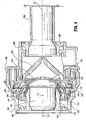
- FIGS. 1-2 illustrate the seal assembly 100 of the present disclosure mounted to cannula assembly 200.
- Cannula assembly 200 may be any conventional cannula suitable for the intended purpose of accessing a body cavity and permit introduction of instruments therethrough.
- Cannula assembly 200 is particularly adapted for use in laparoscopic surgery where the peritoneal cavity is insufflated with a suitable gas, e.g., CO 2 , to raise the cavity wall from the internal organs therein.
- Cannula assembly 200 is typically used with an obturator assembly (not shown) which is a sharp pointed instrument positionable within the passageway of the cannula assembly 200. The obturator assembly is utilized to penetrate the abdominal wall and then subsequently removed from the cannula assembly to permit introduction of the surgical instrumentation utilized to perform the procedure.
- Cannula assembly 200 includes cannula sleeve 202 and cannula housing 204 mounted to an end of the sleeve 202.
- Cannula sleeve 202 defines a longitudinal axis "a" extending along the length of sleeve 202.
- Sleeve 202 further defines an internal longitudinal passage dimensioned to permit passage of surgical instrumentation.
- Sleeve 202 may be formed of stainless steel or other rigid materials such as a polymeric material or the like.
- Sleeve 202 may be clear or opaque.
- the diameter of sleeve 202 may vary, but typically ranges from 10 to 15 mm for use with the seal assembly 100 of the present disclosure.
- Cannula housing 204 includes two components, specifically, housing flange 206 which is attached to the proximal end of cannula sleeve 202 and main housing 208 as shown in FIGS. 3-4 .
- Main housing 208 is connectable to housing flange 206 through a bayonet coupling consisting of radially spaced tongues 210 on the exterior of housing flange 206 and corresponding recesses 212 within the interior of main housing 208.
- Tongues 210 are receivable within recesses 212.
- housing flange 206 and main housing 208 are rotated to securely lock the tongues 210 within the recesses 212.
- Main housing 208 further includes diametrically opposed housing grips 214 dimensioned and arranged for gripping engagement by the fingers of the user.
- cannula housing 204 may be a single component and attached to cannula sleeve 202 by any of the aforementioned means.
- cannula housing 204 further includes duck bill or zero closure valve 216 which tapers distally and inwardly to a sealed configuration as shown in the figure.
- Valve 216 opens to permit passage of the surgical instrumentation and closes in the absence of the instrumentation.
- Valve 216 is preferably adapted to close upon exposure to the forces exerted by the insufflation gases in the internal cavity.
- Other zero closure valves are also contemplated including single or multiple slit valve arrangements, trumpet valves, flapper valves, etc.
- Seal assembly 100 includes seal housing, generally identified as reference numeral 102, and gimbal mount 104 which is disposed within the seal housing 102.
- Seal housing 102 houses the sealing components of the assembly and defines the outer valve or seal body of the seal assembly 100.
- Seal housing 102 defines central seal housing axis "b" which is preferably parallel to the axis "a" of cannula sleeve 202 and, more specifically, coincident with the axis "a" of the cannula.
- Seal housing 102 incorporates three housing components, namely, proximal, distal and inner housing components 106, 108, 110, respectively, which, when assembled together, form the seal housing 102. Assembly of housing components 106, 108, 110 may be affected by any of the aforementioned connection means discussed with respect to cannula housing 204. Further, seal housing 102 may be considered as having an upper housing portion 109 formed by components 106 108, as shown separately in FIGS. 10-12 , and a detachable lower housing portion formed by component 110.
- Proximal housing component 106 defines inner guide wall 112 and outer wall 114 disposed radially outwardly of the inner guide wall 112.
- Inner guide wall 112 defines central passage 116 which is dimensioned to receive a surgical instrument and laterally confine the instrument within seal housing 102.
- Inner guide wall 112 is generally cylindrical in configuration and terminates in a distal arcuate surface 118.
- Outer wall 114 defines first and second annular recesses 120, 122 adjacent its distal end. Recesses 120, 122 receive corresponding structure, e.g., annular lips 124, 126 of distal housing component 108 to facilitate connection of the two components.
- proximal housing component 106 may also incorporate locking tabs which engage corresponding structure of distal housing component 108 upon relative rotation of the components 106, 108 to securely connect the components.
- Inner housing component 110 is disposed within the interior of distal housing component 108 and securely connectable to the distal housing component 108 through a bayonet coupling.
- Such coupling includes radially spaced tongues 128 which depend radially inwardly to be received within correspondingly arranged grooves or recesses 130 on the exterior of inner housing component 110. Coupling of distal and inner housing components 108, 110 is thereby affected through simple rotation of the components.
- seal assembly 100 further includes skirt seal 132 mounted about the proximal end of inner housing component 110 or on the upper surface of the inner housing component (constituting a lower component) of the seal housing.
- Skirt seal 132 functions in minimizing the loss of insufflation gases through seal assembly 102.
- Skirt seal 132 also engages gimbal mount 104'and serves to bias the gimbal mount in a proximal direction against inner guide wall 112 of proximal housing 106 as will be discussed.
- Skirt seal 132 is preferably fabricated from a suitable elastomeric material or the like to provide a spring-like characteristic sufficient to appropriately bias gimbal mount 104.
- gimbal mount 104 is accommodated within an annular space 134 defined between inner and outer walls 112, 114 of proximal housing component 106.
- Gimbal mount 104 is mounted in a manner which permits angulation of the gimbal mount 104 relative to seal axis "b".
- gimbal mount 104 is free to angulate about an axis or center of rotation "c" through a range of motion defined within the confines of annular space 134.
- An annular stop 136 may extend within annular space 134.
- Annular stop 136 is positioned to limit the degree of angulation of gimbal mount 104 if desired. The range of movement of gimbal mount 104 will be discussed in greater detail hereinbelow.
- Gimbal mount 104 includes first and second gimbal housings 138, 140 and resilient seal member 142 which is mounted between the housings 138, 140.
- first and second gimbal housings 138, 140 and seal member 142 each define a general hemispherical configuration as shown.
- First gimbal housing 138 is preferably seated within second gimbal housing 140 and secured to the second gimbal housing 140 through a snap fit connection or the like.
- first gimbal housing 138 includes a plurality of mounting legs 144 radially spaced about the outer periphery of the housing component 134. Legs 144 define locking surfaces 146 which extend in general transverse relation to the axis "b" of seal assembly 200.
- second gimbal housing 140 includes a plurality of corresponding locking detents 148 spaced about the interior of the housing 140.
- first gimbal housing 138 Upon insertion of first gimbal housing 138 within second gimbal housing 140, mounting legs 144 slide along locking detents 148 whereby upon clearing the detents 148, locking surfaces 146 of the mounting legs 146 securely engage the locking detents 148 to fix first gimbal housing 138 within second gimbal housing 140 and securing resilient seal member 142 between the components in sandwiched relation.
- first gimbal housing 138 may be sufficiently resilient to deflect upon insertion to permit mounting legs 144 to clear locking detents 148 and return to their initial position to engage the detents 148.
- seal member 142 of gimbal mount 104 is secured in interposed relation between first and second gimbal housings 138, 140.
- Seal member 142 preferably comprises a resilient center material (e.g., polyisoprene or natural rubber) with first and second layers of fabric 150, 152 impregnated on the respective proximal and distal surfaces of the resilient center material.
- Fabric may be of any suitable fabric for example, a SPANDEX material containing about 20% LYCRA and about 80% NYLON available from Milliken.
- a suitable seal member or seal type is disclosed in commonly assigned U.S. Patent No. 6,482,181, filed November 24, 1999 .
- Seal member 142 defines central aperture 154 for sealed reception of a surgical instrument
- first layer 150 is arranged to extend or overlap into aperture 154.
- the fabric (which is stronger relative to the resilient material) is positioned to engage the surgical instrument upon passage through aperture 154 of seal member 142 thereby protecting the resilient material defining the aperture. This advantageously minimizes the potential of piercing, penetrating or tearing of the resilient material by the instrument.
- an additional layer of fabric 151 on the proximal surface of seal member 142 may be superposed and arranged to drape within aperture 154.
- Seal member 142 includes an annular depression 156 on its distal surface, i.e., within second layer 152 of fabric. Depression 156 receives ledge 158 of second gimbal housing 140 to facilitate fixation of seal member 142 between first and second gimbal housings 138, 140.
- FIG. 6 illustrates annular depressions 153, 155 which have been pressed by a molding tool into layer 153.
- One or more similar depressions may be pressed into layer 150 to assist positioning of fabric during manufacture of seal member 142.
- gimbal mount 104 is free to move within the annular space 134 defined between inner and outer walls 112,114 to permit angulation of the instrument relative to the seal axis "b" while still maintaining a seal thereabout.
- gimbal mount 104 is adapted for swiveling movement about a center of rotation "c" which is coincident with the axis of seal assembly 100.
- the axis of the aperture 154 of seal member 142 intersects the axis "b" of the seal assembly 100 during angulation of the instrument.
- gimbal mount 104 is only in contact with seal housing 102 along distal arcuate surface 118 of proximal housing 106 as well as along skirt seal 132. Specifically, the arcuate inner surface of first gimbal housing 13 8 rides along distal arcuate surface 118 of inner wall 112 in contacting relation therewith (under the bearing influence of skirt seal 132) to permit gimbal mount 104 to swivel within seal housing 102.
- a lubricant may be provided between distal arcuate surface 118 and the inner surface of first gimbal housing 138 to facilitate angulation.
- gimbal mount 104 may angulate or rotate through an angle inclusive of about 25°, more preferably about 22.5° relative to seal axis "b".
- Annular stop 136 may further restrict angulation by a couple of degrees of movement to be inclusive of an angle of about 19° relative to axis "b".
- Seal assembly 100 may be associated with, or joined to, cannula assembly 200 in a variety of ways.
- seal housing 102 of seal assembly 100 and cannula housing 204 of cannula assembly 200 are adapted to detachably engage each other, e.g., through a bayonet lock or like mechanical means.
- proximal and distal housing components 106, 108 may define an upper housing component 109 which is mountable directly to cannula assembly 200.
- inner housing portion 110 which defines a lower housing component may be directly mounted to cannula assembly 200 independent of the upper housing component 109.
- the lower housing component 110 which houses gimbal mount 104 may be mounted to cannula assembly independent of the remaining housing components.
- upper housing may then be mounted to lower housing or cannula assembly 200 as needed. Even further, upper housing component 109 may be mounted to cannula assembly 200 without lower housing component 110. Other means of joining seal assembly 100 to cannula assembly 200 will be readily apparent to one of ordinary skill in the art.
- Seal assembly 100 is mounted to cannula assembly 200 which is previously introduced into an insufflated abdominal cavity.
- An instrument is inserted into seal assembly 100 through passage 116 of inner cylindrical guide wall 112 in seal housing 102. If the axis of the instrument is not perfectly aligned with the axis "a" of cannula assembly 200 or axis "b" of seal assembly 100, then the surgical instrument will contact the inner guide wall 112 and/or the inner surface of seal member 142.
- gimbal mount 104 contacts with the seal member 142 causes gimbal mount 104 to swivel within seal housing 102, thereby bringing aperture 154 into alignment with the surgical instrument Aperture 154 stretches to accommodate the instrument diameter, as necessary.
- the instrument passes further distally into the cannula housing 204 passing through duckbill valve 216 and cannula sleeve 202 into the body cavity.
- gimbal mount 104 is free to swivel further with respect to seal housing 102.
- gimbal mount 104 is free to swivel relative to housing 102, thereby allowing seal member 142 to maintain sealing engagement with the instrument passed therethrough.
Claims (16)
- Ensemble d'étanchéité (100) pour utilisation avec un dispositif d'accès (200), qui comprend:un boîtier d'étanchéité (102) définissant un axe longitudinal central (b), le boîtier d'étanchéité (102) comprenant une paroi interne (112) et une paroi externe (114), la paroi interne définissant une ouverture longitudinale (116) pour permettre le passage d'instruments à travers le boîtier d'étanchéité; etune suspension à cardan (104) au moins partiellement logée dans un espace (134) défini entre la paroi interne et la paroi externe du boîtier d'étanchéité, la suspension à cardan comportant un élément d'étanchéité (142) définissant une ouverture (154) pour une réception sensiblement étanche d'un instrument chirurgical, la suspension à cardan étant conçue pour un mouvement angulaire relativement à l'axe longitudinal central lors de l'angulation de l'instrument chirurgical tout en maintenant sensiblement la réception étanche de l'instrument chirurgical, caractérisé en ce que:la paroi interne définit une surface distale arquée (118) en relation de contact avec une surface interne arquée correspondante de la suspension à cardan.
- Ensemble d'étanchéité selon la revendication 1, dans lequel le boîtier d'étanchéité comprend un joint d'étanchéité à collerette (132), le joint d'étanchéité à collerette étant positionné autour de la suspension à cardan et conçu pour réduire à un minimum le passage de fluides à travers le boîtier d'étanchéité.
- Ensemble d'étanchéité selon la revendication 2, dans laquelle le joint d'étanchéité à collerette s'étend pour venir en contact avec la suspension à cardan, le joint d'étanchéité à collerette étant apte à solliciter la suspension à cardan dans une direction générale proximale.
- Ensemble d'étanchéité selon la revendication 3, dans lequel le joint d'étanchéité à collerette est dimensionné et configuré pour solliciter la suspension à cardan contre une portion de la paroi interne du boîtier d'étanchéité.
- Ensemble d'étanchéité selon l'une quelconque des revendications précédentes, dans lequel l'élément d'étanchéité comporte un élément résiliant et au moins une couche de protection (150, 152) juxtaposée relativement à l'élément résiliant.
- Ensemble d'étanchéité selon la revendication 5, dans lequel la au moins une couche de protection de l'élément d'étanchéité s'étend au moins partiellement dans l'ouverture pour protéger des portions de l'élément d'étanchéité définissant l'ouverture durant le passage de l'instrument chirurgical.
- Ensemble d'étanchéité selon la revendication 5 ou 6, dans lequel la au moins une couche de protection comporte un matériau d'étoffe.
- Ensemble d'étanchéité selon l'une quelconque des revendications précédentes, dans lequel le boîtier d'étanchéité est conçu pour être monté amoviblement sur un ensemble de canule (200) afin de réaliser un joint sensiblement étanche au fluide lorsque ledit instrument est inséré dans l'ensemble d'étanchéité et à travers l'ensemble de canule.
- Ensemble d'étanchéité selon l'une quelconque des revendications précédentes, dans lequel la suspension à cardan définit une configuration générale hémisphérique.
- Ensemble d'étanchéité selon l'une quelconque des revendications précédentes, dans lequel la surface interne arquée de la suspension à cardan est en relation de contact avec la surface distale arquée du boîtier d'étanchéité de sorte que la surface interne arquée traverse la surface distale arquée lors d'un mouvement angulaire de l'instrument chirurgical.
- Ensemble d'étanchéité selon l'une quelconque des revendications précédentes, dans lequel le boîtier d'étanchéité est associé à un ensemble de canule (200).
- Ensemble d'étanchéité selon la revendication 2 ou l'une quelconque des revendications précédentes, dépendant de la revendication 2, dans lequel l'ensemble d'étanchéité comporte une portion de boîtier supérieure (109) et une portion de boîtier inférieure (110), et la collerette est associée à la portion de boîtier inférieure.
- Ensemble d'étanchéité selon la revendication 12, dans lequel le joint d'étanchéité à collerette est disposé sur une surface supérieure de la portion de boîtier inférieure.
- Ensemble d'étanchéité selon la revendication 12 ou 13, dépendant de la revendication 11, dans lequel la portion de boîtier inférieure est fixée à l'ensemble de canule, et la portion de boîtier supérieure peut être fixée amoviblement à au moins une parmi la portion de boîtier inférieure et l'ensemble de canule.
- Ensemble d'étanchéité selon l'une quelconque des revendications précédentes, dans lequel la surface interne arquée de la suspension à cardan se déplace le long de la surface distale arquée de la paroi interne du boîtier d'étanchéité en une relation de contact pour permettre à la suspension à cardan de pivoter dans le boîtier d'étanchéité.
- Ensemble d'étanchéité selon la revendication 15, dans lequel la suspension à cardan est agencée en vue d'un mouvement de pivotement autour d'un centre de rotation (c) qui coïncide avec l'axe longitudinal central du boîtier d'étanchéité.
Priority Applications (2)
| Application Number | Priority Date | Filing Date | Title |
|---|---|---|---|
| EP20100182020 EP2263575B1 (fr) | 2002-05-10 | 2003-04-24 | Joint d'étanchéité pour introducteur |
| EP09015886.6A EP2165667B1 (fr) | 2002-05-10 | 2003-04-24 | Ensemble de joint d'introducteur |
Applications Claiming Priority (5)
| Application Number | Priority Date | Filing Date | Title |
|---|---|---|---|
| US37965102P | 2002-05-10 | 2002-05-10 | |
| US379651P | 2002-05-10 | ||
| US10/264,556 US20040066008A1 (en) | 2002-10-04 | 2002-10-04 | Introducer seal assembly |
| US264556 | 2002-10-04 | ||
| PCT/US2003/012894 WO2003094760A2 (fr) | 2002-05-10 | 2003-04-24 | Joint d'etancheite pour introducteur |
Related Child Applications (2)
| Application Number | Title | Priority Date | Filing Date |
|---|---|---|---|
| EP09015886.6A Division EP2165667B1 (fr) | 2002-05-10 | 2003-04-24 | Ensemble de joint d'introducteur |
| EP20100182020 Division EP2263575B1 (fr) | 2002-05-10 | 2003-04-24 | Joint d'étanchéité pour introducteur |
Publications (2)
| Publication Number | Publication Date |
|---|---|
| EP1503680A2 EP1503680A2 (fr) | 2005-02-09 |
| EP1503680B1 true EP1503680B1 (fr) | 2009-12-23 |
Family
ID=29423232
Family Applications (1)
| Application Number | Title | Priority Date | Filing Date |
|---|---|---|---|
| EP03736492A Expired - Lifetime EP1503680B1 (fr) | 2002-05-10 | 2003-04-24 | Joint d'etancheite pour introducteur |
Country Status (7)
| Country | Link |
|---|---|
| EP (1) | EP1503680B1 (fr) |
| JP (2) | JP4365781B2 (fr) |
| AU (2) | AU2003237108B2 (fr) |
| CA (1) | CA2484321C (fr) |
| DE (1) | DE60330661D1 (fr) |
| ES (1) | ES2338224T3 (fr) |
| WO (1) | WO2003094760A2 (fr) |
Cited By (1)
| Publication number | Priority date | Publication date | Assignee | Title |
|---|---|---|---|---|
| US8968249B2 (en) | 2002-05-10 | 2015-03-03 | Covidien Lp | Introducer seal assembly |
Families Citing this family (18)
| Publication number | Priority date | Publication date | Assignee | Title |
|---|---|---|---|---|
| US20040066008A1 (en) | 2002-10-04 | 2004-04-08 | Smith Robert C. | Introducer seal assembly |
| US8206411B2 (en) | 2003-09-30 | 2012-06-26 | Ethicon Endo-Surgery, Inc. | Trocar housing/stop-cock assembly |
| AU2004214616B2 (en) * | 2003-09-30 | 2009-11-12 | Ethicon Endo-Surgery, Inc. | Improved trocar housing/stop-cock assembly |
| US8070767B2 (en) * | 2005-01-28 | 2011-12-06 | Tyco Healthcare Group Lp | Optical penetrating adapter for surgical portal |
| US7582071B2 (en) | 2005-03-28 | 2009-09-01 | Tyco Healthcare Group Lp | Introducer seal assembly |
| US7931624B2 (en) * | 2005-04-05 | 2011-04-26 | Tyco Healthcare Group Lp | Introducer seal assembly with low profile gimbal seal |
| US8118783B2 (en) | 2008-01-30 | 2012-02-21 | Tyco Healthcare Group Lp | Access assembly with spherical valve |
| US8092430B2 (en) | 2008-03-03 | 2012-01-10 | Tyco Healthcare Group Lp | Single port device with multi-lumen cap |
| US8206357B2 (en) | 2009-03-26 | 2012-06-26 | Tyco Healthcare Group Lp | Articulating surgical portal apparatus with spring |
| EP2515774B1 (fr) * | 2009-12-23 | 2014-03-19 | Alcon Research, Ltd. | Canule de trocart ophthalmique a valve |
| WO2013065292A1 (fr) * | 2011-10-31 | 2013-05-10 | 住友ベークライト株式会社 | Instrument médical de dilatation et ensemble d'instrument médical de dilatation |
| US10299778B2 (en) | 2012-05-15 | 2019-05-28 | Covidien Lp | Surgical access device including gimbal mount cooperating with bellows |
| US9486242B2 (en) | 2012-05-15 | 2016-11-08 | Covidien Lp | Surgical access device including gimbal seal with self-centering mechanism |
| US9901372B2 (en) | 2013-02-21 | 2018-02-27 | Covidien Lp | Surgical access device including gimbal mount cooperating with bellows attached to proximal wall of seal housing |
| JP6633558B2 (ja) * | 2017-01-31 | 2020-01-22 | 京セラ株式会社 | トロカール装置 |
| CN107348998A (zh) * | 2017-07-14 | 2017-11-17 | 苏州朗特斯医疗科技有限公司 | 一种鱼眼式单孔多通道穿刺器 |
| CN108784797A (zh) * | 2018-06-29 | 2018-11-13 | 杭州康基医疗器械股份有限公司 | 穿刺器固定装置及穿刺器组件 |
| US11357542B2 (en) | 2019-06-21 | 2022-06-14 | Covidien Lp | Valve assembly and retainer for surgical access assembly |
Family Cites Families (10)
| Publication number | Priority date | Publication date | Assignee | Title |
|---|---|---|---|---|
| US4448449A (en) * | 1981-05-04 | 1984-05-15 | Halling Horace P | Flexible piping joint and method of forming same |
| JPH0266816A (ja) * | 1988-08-31 | 1990-03-06 | Yazaki Corp | グロメット |
| US5342315A (en) * | 1993-04-12 | 1994-08-30 | Ethicon, Inc. | Trocar seal/protector assemblies |
| CA2126150C (fr) * | 1993-07-14 | 2005-02-22 | David T. Green | Montage obturateur facilitant l'introduction d'instruments chirurgicaux |
| US5820600A (en) * | 1996-05-14 | 1998-10-13 | Innerdyne, Inc. | Adjustable introducer valve |
| US5792113A (en) * | 1996-12-12 | 1998-08-11 | Ethicon Endo-Surgerym Inc. | Universal seal for a trocar |
| EP1625863B1 (fr) * | 1997-05-02 | 2007-08-08 | United States Surgical Corporation | Ensemble à canule |
| JP4417438B2 (ja) * | 1997-05-28 | 2010-02-17 | ユナイテッド ステイツ サージカル コーポレイション | トロカールシールシステム |
| US6113106A (en) * | 1997-11-03 | 2000-09-05 | Freudenberg-Nok General Partnership | Gimballed mechanical face seal |
| US6942671B1 (en) * | 2000-11-06 | 2005-09-13 | Tyco Healthcare Group Lp | Surgical sealing apparatus |
-
2003
- 2003-04-24 EP EP03736492A patent/EP1503680B1/fr not_active Expired - Lifetime
- 2003-04-24 JP JP2004502852A patent/JP4365781B2/ja not_active Expired - Lifetime
- 2003-04-24 WO PCT/US2003/012894 patent/WO2003094760A2/fr active Application Filing
- 2003-04-24 DE DE60330661T patent/DE60330661D1/de not_active Expired - Lifetime
- 2003-04-24 CA CA2484321A patent/CA2484321C/fr not_active Expired - Fee Related
- 2003-04-24 ES ES03736492T patent/ES2338224T3/es not_active Expired - Lifetime
- 2003-04-24 AU AU2003237108A patent/AU2003237108B2/en not_active Ceased
-
2008
- 2008-12-22 AU AU2008261180A patent/AU2008261180B2/en not_active Expired
-
2009
- 2009-07-01 JP JP2009157347A patent/JP2009261970A/ja active Pending
Cited By (1)
| Publication number | Priority date | Publication date | Assignee | Title |
|---|---|---|---|---|
| US8968249B2 (en) | 2002-05-10 | 2015-03-03 | Covidien Lp | Introducer seal assembly |
Also Published As
| Publication number | Publication date |
|---|---|
| WO2003094760A2 (fr) | 2003-11-20 |
| AU2008261180B2 (en) | 2011-06-09 |
| CA2484321A1 (fr) | 2003-11-20 |
| WO2003094760A3 (fr) | 2003-12-24 |
| ES2338224T3 (es) | 2010-05-05 |
| EP1503680A2 (fr) | 2005-02-09 |
| JP2009261970A (ja) | 2009-11-12 |
| DE60330661D1 (de) | 2010-02-04 |
| JP2005524482A (ja) | 2005-08-18 |
| JP4365781B2 (ja) | 2009-11-18 |
| CA2484321C (fr) | 2011-06-21 |
| AU2003237108B2 (en) | 2008-10-09 |
| AU2003237108A1 (en) | 2003-11-11 |
| AU2008261180A1 (en) | 2009-01-22 |
Similar Documents
| Publication | Publication Date | Title |
|---|---|---|
| US7632250B2 (en) | Introducer seal assembly | |
| EP2263575B1 (fr) | Joint d'étanchéité pour introducteur | |
| EP1709918B1 (fr) | Joint d'étanchéité pour introducteur comprenant un joint de cardan compact | |
| AU2008261180B2 (en) | Introducer seal assembly | |
| US11540821B2 (en) | Surgical access device including gimbal mount cooperating with bellows | |
| US10772661B2 (en) | Method and structure for selectively locking portions of a seal assembly | |
| EP2160987B1 (fr) | Garniture d'étanchéité pour canule | |
| EP2087846B1 (fr) | Ensemble d'accès avec une valve sphérique | |
| US20110124971A1 (en) | Portal assembly with multi-seal system | |
| AU2011205165A1 (en) | Introducer seal assembly |
Legal Events
| Date | Code | Title | Description |
|---|---|---|---|
| PUAI | Public reference made under article 153(3) epc to a published international application that has entered the european phase |
Free format text: ORIGINAL CODE: 0009012 |
|
| 17P | Request for examination filed |
Effective date: 20041125 |
|
| AK | Designated contracting states |
Kind code of ref document: A2 Designated state(s): AT BE BG CH CY CZ DE DK EE ES FI FR GB GR HU IE IT LI LU MC NL PT RO SE SI SK TR |
|
| AX | Request for extension of the european patent |
Extension state: AL LT LV MK |
|
| DAX | Request for extension of the european patent (deleted) | ||
| RBV | Designated contracting states (corrected) |
Designated state(s): DE ES FR GB IE IT |
|
| 17Q | First examination report despatched |
Effective date: 20070906 |
|
| GRAP | Despatch of communication of intention to grant a patent |
Free format text: ORIGINAL CODE: EPIDOSNIGR1 |
|
| GRAS | Grant fee paid |
Free format text: ORIGINAL CODE: EPIDOSNIGR3 |
|
| GRAA | (expected) grant |
Free format text: ORIGINAL CODE: 0009210 |
|
| AK | Designated contracting states |
Kind code of ref document: B1 Designated state(s): DE ES FR GB IE IT |
|
| REG | Reference to a national code |
Ref country code: GB Ref legal event code: FG4D |
|
| REG | Reference to a national code |
Ref country code: IE Ref legal event code: FG4D |
|
| REF | Corresponds to: |
Ref document number: 60330661 Country of ref document: DE Date of ref document: 20100204 Kind code of ref document: P |
|
| REG | Reference to a national code |
Ref country code: ES Ref legal event code: FG2A Ref document number: 2338224 Country of ref document: ES Kind code of ref document: T3 |
|
| PLBE | No opposition filed within time limit |
Free format text: ORIGINAL CODE: 0009261 |
|
| STAA | Information on the status of an ep patent application or granted ep patent |
Free format text: STATUS: NO OPPOSITION FILED WITHIN TIME LIMIT |
|
| 26N | No opposition filed |
Effective date: 20100924 |
|
| PGFP | Annual fee paid to national office [announced via postgrant information from national office to epo] |
Ref country code: ES Payment date: 20120426 Year of fee payment: 10 |
|
| PGFP | Annual fee paid to national office [announced via postgrant information from national office to epo] |
Ref country code: IT Payment date: 20141030 Year of fee payment: 12 |
|
| REG | Reference to a national code |
Ref country code: ES Ref legal event code: FD2A Effective date: 20150529 |
|
| PG25 | Lapsed in a contracting state [announced via postgrant information from national office to epo] |
Ref country code: ES Free format text: LAPSE BECAUSE OF NON-PAYMENT OF DUE FEES Effective date: 20140425 |
|
| PG25 | Lapsed in a contracting state [announced via postgrant information from national office to epo] |
Ref country code: IT Free format text: LAPSE BECAUSE OF NON-PAYMENT OF DUE FEES Effective date: 20150424 |
|
| REG | Reference to a national code |
Ref country code: FR Ref legal event code: PLFP Year of fee payment: 14 |
|
| REG | Reference to a national code |
Ref country code: FR Ref legal event code: PLFP Year of fee payment: 15 |
|
| REG | Reference to a national code |
Ref country code: FR Ref legal event code: PLFP Year of fee payment: 16 |
|
| PGFP | Annual fee paid to national office [announced via postgrant information from national office to epo] |
Ref country code: IE Payment date: 20220323 Year of fee payment: 20 Ref country code: GB Payment date: 20220323 Year of fee payment: 20 |
|
| PGFP | Annual fee paid to national office [announced via postgrant information from national office to epo] |
Ref country code: FR Payment date: 20220323 Year of fee payment: 20 |
|
| PGFP | Annual fee paid to national office [announced via postgrant information from national office to epo] |
Ref country code: DE Payment date: 20220322 Year of fee payment: 20 |
|
| REG | Reference to a national code |
Ref country code: DE Ref legal event code: R071 Ref document number: 60330661 Country of ref document: DE |
|
| REG | Reference to a national code |
Ref country code: GB Ref legal event code: PE20 Expiry date: 20230423 |
|
| REG | Reference to a national code |
Ref country code: IE Ref legal event code: MK9A |
|
| PG25 | Lapsed in a contracting state [announced via postgrant information from national office to epo] |
Ref country code: IE Free format text: LAPSE BECAUSE OF EXPIRATION OF PROTECTION Effective date: 20230424 |
|
| PG25 | Lapsed in a contracting state [announced via postgrant information from national office to epo] |
Ref country code: GB Free format text: LAPSE BECAUSE OF EXPIRATION OF PROTECTION Effective date: 20230423 |