EP1503164A1 - Sammelrohr eines Wärmeübertragers, insbesondere eines Heizkörpers für ein Kraftfahrzeug - Google Patents
Sammelrohr eines Wärmeübertragers, insbesondere eines Heizkörpers für ein Kraftfahrzeug Download PDFInfo
- Publication number
- EP1503164A1 EP1503164A1 EP03291862A EP03291862A EP1503164A1 EP 1503164 A1 EP1503164 A1 EP 1503164A1 EP 03291862 A EP03291862 A EP 03291862A EP 03291862 A EP03291862 A EP 03291862A EP 1503164 A1 EP1503164 A1 EP 1503164A1
- Authority
- EP
- European Patent Office
- Prior art keywords
- collecting tube
- pipe
- tube
- heat exchanger
- flattened
- Prior art date
- Legal status (The legal status is an assumption and is not a legal conclusion. Google has not performed a legal analysis and makes no representation as to the accuracy of the status listed.)
- Granted
Links
- 239000000853 adhesive Substances 0.000 claims description 17
- 230000001070 adhesive effect Effects 0.000 claims description 17
- 229910052751 metal Inorganic materials 0.000 claims description 7
- 239000002184 metal Substances 0.000 claims description 7
- 238000010438 heat treatment Methods 0.000 claims description 6
- 238000004378 air conditioning Methods 0.000 claims description 5
- 238000005096 rolling process Methods 0.000 claims description 3
- 239000012530 fluid Substances 0.000 claims 4
- 238000005452 bending Methods 0.000 claims 1
- 238000003466 welding Methods 0.000 abstract description 7
- 238000004026 adhesive bonding Methods 0.000 description 7
- 239000002826 coolant Substances 0.000 description 6
- 239000003292 glue Substances 0.000 description 5
- 238000004519 manufacturing process Methods 0.000 description 5
- 239000011324 bead Substances 0.000 description 4
- 239000007788 liquid Substances 0.000 description 4
- 239000000463 material Substances 0.000 description 3
- 238000005476 soldering Methods 0.000 description 3
- 239000003570 air Substances 0.000 description 2
- 229910052782 aluminium Inorganic materials 0.000 description 2
- XAGFODPZIPBFFR-UHFFFAOYSA-N aluminium Chemical compound [Al] XAGFODPZIPBFFR-UHFFFAOYSA-N 0.000 description 2
- 238000002485 combustion reaction Methods 0.000 description 2
- 238000000034 method Methods 0.000 description 2
- 238000002604 ultrasonography Methods 0.000 description 2
- 208000034656 Contusions Diseases 0.000 description 1
- 206010053648 Vascular occlusion Diseases 0.000 description 1
- 239000012080 ambient air Substances 0.000 description 1
- 230000006835 compression Effects 0.000 description 1
- 238000007906 compression Methods 0.000 description 1
- 238000005516 engineering process Methods 0.000 description 1
- 230000002349 favourable effect Effects 0.000 description 1
- 210000001061 forehead Anatomy 0.000 description 1
- 230000005484 gravity Effects 0.000 description 1
- 238000009434 installation Methods 0.000 description 1
- 230000004048 modification Effects 0.000 description 1
- 238000012986 modification Methods 0.000 description 1
- 238000007789 sealing Methods 0.000 description 1
- 229940034610 toothpaste Drugs 0.000 description 1
- 239000000606 toothpaste Substances 0.000 description 1
Images


Classifications
-
- F—MECHANICAL ENGINEERING; LIGHTING; HEATING; WEAPONS; BLASTING
- F28—HEAT EXCHANGE IN GENERAL
- F28F—DETAILS OF HEAT-EXCHANGE AND HEAT-TRANSFER APPARATUS, OF GENERAL APPLICATION
- F28F9/00—Casings; Header boxes; Auxiliary supports for elements; Auxiliary members within casings
- F28F9/02—Header boxes; End plates
- F28F9/0202—Header boxes having their inner space divided by partitions
-
- F—MECHANICAL ENGINEERING; LIGHTING; HEATING; WEAPONS; BLASTING
- F28—HEAT EXCHANGE IN GENERAL
- F28F—DETAILS OF HEAT-EXCHANGE AND HEAT-TRANSFER APPARATUS, OF GENERAL APPLICATION
- F28F2220/00—Closure means, e.g. end caps on header boxes or plugs on conduits
Definitions
- the invention relates to a manifold of a heat exchanger, in particular a radiator for a heating or air conditioning system of a motor vehicle according to the preamble of claim 1.
- the invention relates also a heat exchanger, in particular a radiator with side by side arranged headers after Oberbergriff the additional claim 14th
- Hoppers and radiators of the above type were by a distributed by the Applicant, on the market radiator for Heating or air conditioning systems of motor vehicles known.
- the known Heat exchanger is a mechanically joined pipe fork heater, wherein the ends of the pipe forks in two adjacent collecting pipes lead.
- the pipe forks have straight legs (round tubes), on which ribs as secondary heat exchange surfaces by mechanical Expansion of the pipes are attached.
- the radiator will be over his Collecting pipes to a coolant circuit of an internal combustion engine of a Motor vehicle connected, so that the pipe forks of coolant be passed through which its heat through the ribs to ambient air dissipates, which fed to a passenger compartment of the motor vehicle becomes.
- the connection between the pipe ends of the pipe forks and the Hoppers is glued - but the headers have passages or Collar in which the pipe ends are inserted and glued.
- the Manifolds are connected with one end to the coolant circuit, while the other end of each manifold sealed is.
- the ends of the manifolds are compressed and soldered, so that a pressure- and coolant-tight fold arises.
- This Lötfalz is atypical insofar as the entire radiator mechanically added, d. H. not soldered. The soldering is opposite to the mechanical one Add manufacturing technology consuming and causes higher production costs.
- headers or heat exchangers of the aforementioned type with less production costs and to produce at a lower cost.
- the manifolds end by a Bonded or welded connection are closed. Since the headers as Aluminum pipes are formed, according to the invention is a metal adhesive used. By gluing or welding, the advantage is achieved that the closure of the headers are manufactured at a lower cost can. In particular, the gluing does not require a complex heat treatment like soldering.
- the open end of the manifold initially mechanically (plastically) deformed, so that a Joint for gluing or welding is formed.
- the Closing the headers can be done either before or after the connection the headers with the pipe ends of the heat exchanger or Radiator done.
- the pipe end is flattened and at the end forms an open fillet weld, which is glued or welded can.
- the pipe end in two vertical flattened to each other extending directions, so that an approximately double T-shaped butt weld results, which is well weldable.
- the pipe end by mechanical rolling (using a roller set) to one spherical end region, d. H. approximately hemispherical formed, what in Principle already sufficient for a tight seal.
- the middle portion of the pipe end is sealed by a spot weld, to minimize the risk of leakage.
- the pipe end is first flattened and then angled at right angles, so that one after is formed above open joint for receiving a 'glue.
- the sticking i. H. the application of the metal adhesive simultaneously with the production of the adhesive joint between pipe ends and passing through the headers, d. H. in one operation.
- the pipe end flattened and has a transverse in the flattened end Channel filled with a glue.
- This is the tightness made of the closure.
- both Adhesive joints at the manifold at the same time, d. H. in a common Operation can be made.
- the Channel for receiving the adhesive parallel to the longitudinal direction of the radiator tubes runs and can therefore be easily filled from above with glue.
- the pipe end closed by a lid which glued to the pipe end either or welded is closed by a lid which glued to the pipe end either or welded.
- the lid is designed as a plug, is pressed into the tube and with the Pipe end forms a butt weld, which is easily weldable.
- Another advantageous variant also provides a stopper, the one with Glue filled ring channel is surrounded. The adhesive is thereby by a Filling opening filled from above. Again, the gluing process in one Operation with the bonding of the pipe ends of the radiator pipes respectively.
- the pipe end to a Ring flange formed with a flat surface, on which a lid is placed and is welded by ultrasound to the annular flange.
- that pipe end and lid is very simple and therefore are easy to produce.
- the ultrasonic welding is a clean Method with a heat development limited to the joint, so that no distortion of the components occurs.
- the invention is also solved by the features of claim 14, being for a heat exchanger or radiator with two side by side lying collecting pipes according to the invention provided that both Headers are made of a tube which is U-shaped bent, flattened in the area of the bow and by pinching or Abkantung is sealed. This achieves the advantage that both manifolds in one operation from one part, d. H. made without additional parts and closed at the end, without the need for gluing or welding would. Both headers are thus physically part, communicate but not with each other.
- Fig . 1 shows a view of a mechanically joined radiator 1 according to the prior art.
- This known radiator 1 was sold by the applicant and installed in heating or air conditioning systems of motor vehicles.
- the radiator 1 has a mechanically joined net 2, which consists of pipe forks 3 and a rib block 4 mechanically connected to the pipe forks 3.
- the pipe forks 3 have pipe ends 5, which open into a manifold 6.
- a second manifold 7 is parallel to the manifold 6, in which the pipe ends of the second leg of the pipe forks 3 open.
- the manifolds 6, 7 each have a connection 6a, 7a, via which the radiator 1 can be connected to a coolant circuit, not shown, of an internal combustion engine of a motor vehicle.
- the radiator 1 is thus twice through the coolant in two rows of tubes, ie flows through from top to bottom and from bottom to top and - acted upon in Fig. 1 - perpendicular to the plane of air.
- the air flow direction is indicated by an arrow L.
- Fig. 1c shows a partial section along the line Ic-Ic through the manifold 6, which has inwardly directed passages 8.
- the pipe ends 5 are inserted and glued and sealed in a manner not shown.
- the pipe forks 3, the manifolds 6, 7 and the ribbed package 4 are made of aluminum materials.
- the headers 6, 7 each have end closures 9, 10, the each formed as a soldered flat fold.
- the ends of the headers 6, 7 are thus - similar to a toothpaste tube - flattened at the end or compressed and then to achieve the required compressive strength and soldered tightness.
- the soldering of the closures 9, 10 must be separate take place, d. H. before the headers 6, 7 connected to the pipe forks 3 and glued. This is the state of the art of which the hereinafter described invention.
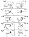
- Fig. 2 shows a first embodiment of the invention for a manifold closure 11, which corresponds to the previously described closures 9, 10 in the prior art, ie functionally and with respect to the arrangement of the manifold.
- the closure 11 is achieved by flattening and compressing a collecting tube 12 with a round cross-section, wherein an upper layer 11a comes to lie on a lower layer 11b, but the end face an approximately V-shaped groove 13 is formed.
- the channel 13 is closed by either an adhesive or a weld 14.
- the manifold 12 is sufficiently pressure and liquid sealed.
- FIG. 2 a shows a perspective view of the closure 11 with a front-side weld 14, which is designed as a fillet weld in the channel 13.
- Fig. 3 shows a second embodiment for a closure 15 of a manifold 16.
- the end of the manifold 16 is deformed in two mutually perpendicular directions, ie flattened in one direction and compressed, then or simultaneously carried a compression in a 90 degrees offset Direction, so that as a forehead profile - as seen in Fig. 3a recognizable - about a double-T profile results, which is closed by a butt weld 17.
- the manifold 16 is pressure and liquid sealed.
- Fig. 4 shows a third embodiment of the closure of a manifold 18, in which a cup-shaped plug 19 is pressed, so that the end faces of the manifold 18 and plug 19 are flush and can be closed by a butt weld 20.
- FIG. 4 a shows a perspective view with a view of the end-side annular butt weld 20.
- Fig. 5, 5a show a fourth embodiment of a closure for a collection tube 21, the tube end 22 is formed by rolling to a spherical, approximately hemispherical end portion. The tube material is thereby rolled inward in the direction of the tube axis a, that in the region of the axis a and the piercing point M sufficient material is available to complete the manifold 21.
- Fig. 6, 6a show a fifth embodiment of a modification of the fourth embodiment, namely a collecting pipe 21 a with rolled pipe end 22a, whose central region is completely closed and sealed by a weld point 23.
- Fig. 7 shows a sixth embodiment of the closure of a collecting tube 24, the tube end 25 flattened in the region of the tube axis a and (in the drawing) upwards, ie approximately at right angles to the tube axis a is angled, with an approximately V-shaped groove 25 a end is formed.
- the latter is used for filling and for receiving a metal adhesive 26th
- Fig. 7a shows a perspective view of the closure 25 with the upwardly facing groove 25a, which is closed around like a flattened funnel and receives the adhesive 26 in itself.
- Fig. 8 shows a seventh embodiment of a closure 27 for a manifold 28, in the pipe end a cup-shaped plug 29 is pressed so that it is flush with the front end side flush with the pipe end.
- the collecting tube 28 has in the region of the stopper 29 a circumferential bead 30, which forms an annular channel 31 with the outer wall of the stopper 29, which has an uppermost filling opening 31a.
- the annular channel 31 is filled via the filling opening 31a with a metal adhesive which seals the plug 29 against the inner wall of the collecting tube 28 and thus ensures a pressure and liquid-tight closure of the collecting tube 28.
- the bead 30 can also be replaced by a (not shown) inner bead in the plug 29, so that also an annular channel is formed.
- FIG 8a shows a perspective view with a view of the end face of the collecting tube 28, the bead 30 and the filling opening 31a.
- Fig. 9 shows a sixth embodiment of a closure 32 for a manifold 33.
- the pipe end of the manifold 33 is flattened except for a transversely extending to the tube axis a channel 34, ie compressed in the axial direction a in front of and behind the channel 34.
- the channel 34 is filled with a metal adhesive 35 (possible from above or below), whereby the manifold is pressure and liquid sealed.
- 9 a shows a perspective view of the closure 32 with transverse channel 34.
- the filling openings for the metal adhesive are in the embodiments 7, 8 and 9 are each placed so that the bond or the Applicating the adhesive for the connection of the radiator tubes with the Collecting tube can be done simultaneously, without the radiator in this Production step must be changed in its position.
- the glue in the State of application is liquid, it runs, following the gravity of top down, before it hardens.
- the each filling hole is located on the side of the manifold, where the Passages for receiving the pipe ends (see Fig. 1, 1c) are arranged.
- FIGS. 10, 10a show a ninth embodiment of a closure 36 for a collecting tube 37, the end-side end region of which is formed into an annular flange 37a with an end-face planar surface.
- a cover plate 38 which has a corresponding planar surface, placed and welded by means of ultrasound.
- Annular flange 37a and cover 38 are thus sealed by a circumferential weld 39 and firmly together.
- the invention is also applicable to heat exchangers, in particular radiators applicable only to a manifold on one side of the heat exchanger.
- Fig. 11 , 11a show a tenth embodiment of the invention for a radiator with two juxtaposed headers - similar to the radiator in Fig. 1 to 1c.
- the radiator not shown here, has two manifolds 40, 41 which are made of a tube and in the region of their tube ends 40a, 41a by a flattened, angled and U-shaped pipe bend 42 are interconnected.
- the arc 42 connects both manifolds 40, 41 physically, but separates them on the coolant side, by two folds or not shown bruises ..
- This solution has the advantage of a simplified installation with a radiator of FIG. 1 and the further advantage that they no gluing and no welding required for sealing.
Landscapes
- Engineering & Computer Science (AREA)
- Physics & Mathematics (AREA)
- Thermal Sciences (AREA)
- Mechanical Engineering (AREA)
- General Engineering & Computer Science (AREA)
- Heat-Exchange Devices With Radiators And Conduit Assemblies (AREA)
Abstract
Description
- Fig. 1, 1a, 1b, 1c
- einen mechanisch gefügten Heizkörper nach dem Stand der Technik,
- Fig. 2, 2a
- eine erste Ausführung für einen Sammelrohrverschluss,
- Fig. 3, 3a
- eine zweite Ausführung für einen Sammelrohrverschluss,
- Fig. 4, 4a
- eine dritte Ausführung für einen Sammelrohrverschluss,
- Fig. 5, 5a
- eine vierte Ausführung für einen Sammelrohrverschluss,
- Fig. 6, 6a
- eine fünfte Ausführung für einen Sammelrohrverschluss,
- Fig. 7, 7a
- eine sechste Ausführung für einen Sammelrohrverschluss,
- Fig. 8, 8a
- eine siebte Ausführung für einen Sammelrohrverschluss,
- Fig. , 9a
- eine achte Ausführung für einen Sammelrohrverschluss,
- Fig. 10,10a
- eine neunte Ausführung für einen Sammelrohrverschluss und
- Fig. 11,11a
- eine zehnte Ausführung eines Verschlusses zweier Sammelrohre.
Claims (15)
- Sammelrohr eines Wärmeübertragers, insbesondere eines Heizkörpers für eine Heizungs- oder Klimaanlage eines Kraftfahrzeuges, wobei der Wärmeübertrager mindestens eine Reihe von Rohren (3) mit Rohrenden (5) aufweist, die in das Sammelrohr (6) münden, und wobei das Sammelrohr (6) ein offenes Rohrende (6a) für den Zu- oder Abfluss eines Fluids und ein geschlossenes Rohrende mit einem fluid- und druckdichten Verschluss aufweist, dadurch gekennzeichnet, dass der Verschluss als geklebte oder geschweißte Verbindung ausgebildet ist.
- Sammelrohr nach Anspruch 1, dadurch gekennzeichnet, dass die Verbindung mittels eines Metallklebers (14, 26, 35) hergestellt ist.
- Sammelrohr nach Anspruch 1 oder 2, dadurch gekennzeichnet, dass das geschlossene Rohrende mechanisch verformt ist und eine Fügestelle bzw. Fügenaht aufweist.
- Sammelrohr nach Anspruch 3, dadurch gekennzeichnet, dass das Rohrende (11) abgeflacht ist und die Fügenaht als Rinne (13) ausgebildet ist.
- Sammelrohr nach Anspruch 3, dadurch-gekennzeichnet, dass das Rohrende (15) zweifach abgeflacht und die Fügestelle als doppel-T-förmige Stumpfschweißnaht (17) ausgebildet ist.
- Sammelrohr nach Anspruch 3, dadurch gekennzeichnet, dass das Rohrende einen durch Rollen hergestellten, sphärischen Endbereich (22, 22a) mit einer punktförmigen Fügestelle M aufweist, die vorzugsweise durch einen Schweißpunkt (23) abgedichtet ist.
- Sammelrohr nach Anspruch 3, dadurch gekennzeichnet, dass das Rohrende (25) abgeflacht und abgewinkelt ist sowie eine nach oben offene Fügestelle(25a) für einen Kleber (26) aufweist.
- Sammelrohr nach Anspruch 3, dadurch gekennzeichnet, dass das Rohrende einen abgeflachten Endbereich (32) aufweist und dass die Fügestelle als quer zur Rohrachse a verlaufender, mit einem Kleber (35) auffüllbarer Kanal (34) innerhalb des Endbereiches (32) ausgebildet ist.
- Sammelrohr nach Anspruch 8, dadurch gekennzeichnet, dass der Kanal (34) parallel zur Längsrichtung der Rohre des Wärmeübertragers angeordnet ist.
- Sammelrohr nach Anspruch 1 oder 2, dadurch gekennzeichnet, dass das Rohrende durch einen Deckel verschlossen ist.
- Sammelrohr nach Anspruch 10, dadurch gekennzeichnet, dass der Deckel als Stopfen (19) ausgebildet ist, der mit dem Rohrende eine stirnseitige Stumpfschweißnaht (20) bildet.
- Sammelrohr nach Anspruch 10, dadurch gekennzeichnet, dass der Deckel als in das Rohrende (27) einsetzbarer Stopfen (29) ausgebildet und dass zwischen dem Rohrende (27) und dem Stopfen (29) ein mit einem Kleber befüllbaren Ringkanal (31) mit einer oberen Einfüllöffnung (31a) angeordnet ist.
- Sammelrohr nach Anspruch 10, dadurch gekennzeichnet, dass das Rohrende (36) einen' stirnseitigen, ebenen Ringflansch (37a) aufweist und der Deckel (38) mit dem Ringflansch (37a) mittels einer durch UItraschallschweißen erzeugten Schweißnaht (39) verbunden ist.
- Wärmeübertrager, insbesondere Heizkörper mit nebeneinander angeordneten Sammelrohren für eine Heizungs- oder Klimaanlage eines Kraftfahrzeuges, wobei der Wärmeübertrager zwei Reihen von Rohren, insbesondere U-Rohre mit Rohrenden aufweist, die in die Sammelrohre münden, und wobei die Sammelrohre je ein offenes Rohrende für den Zu- oder Abfluss eines Fluids und ein geschlossenes Rohrende mit einem fluid- und druckdichten Verschluss aufweisen, dadurch gekennzeichnet, dass beide Sammelrohre (40, 41) aus einem Rohr hergestellt sind und dass der Verschluss durch einen abgeflachten, die beiden Sammelrohre (40, 41) verbindenden Rohrbogen (42) gebildet wird.
- Wärmeübertrager, insbesondere Heizkörper nach Anspruch 14, dadurch gekennzeichnet, dass der Verschluss der beiden Rohrenden (40a, 41a) durch Quetschungen oder Abkantungen des abgeflachten Rohrbogens (42) gebildet ist.
Priority Applications (1)
| Application Number | Priority Date | Filing Date | Title |
|---|---|---|---|
| EP03291862.5A EP1503164B1 (de) | 2003-07-28 | 2003-07-28 | Wärmeübertrager |
Applications Claiming Priority (1)
| Application Number | Priority Date | Filing Date | Title |
|---|---|---|---|
| EP03291862.5A EP1503164B1 (de) | 2003-07-28 | 2003-07-28 | Wärmeübertrager |
Publications (2)
| Publication Number | Publication Date |
|---|---|
| EP1503164A1 true EP1503164A1 (de) | 2005-02-02 |
| EP1503164B1 EP1503164B1 (de) | 2019-05-01 |
Family
ID=33522460
Family Applications (1)
| Application Number | Title | Priority Date | Filing Date |
|---|---|---|---|
| EP03291862.5A Expired - Lifetime EP1503164B1 (de) | 2003-07-28 | 2003-07-28 | Wärmeübertrager |
Country Status (1)
| Country | Link |
|---|---|
| EP (1) | EP1503164B1 (de) |
Citations (5)
| Publication number | Priority date | Publication date | Assignee | Title |
|---|---|---|---|---|
| JPH07139852A (ja) * | 1993-09-24 | 1995-06-02 | Marunaka:Kk | 熱交換器用パイプのキャップ |
| US5441100A (en) * | 1992-06-02 | 1995-08-15 | Showa Aluminum Corporation | Heat exchanger |
| JPH09229582A (ja) * | 1996-02-21 | 1997-09-05 | Zexel Corp | 熱交換器のキャップ構造 |
| JPH09264686A (ja) * | 1996-03-27 | 1997-10-07 | Zexel Corp | 熱交換器のキャップ構造 |
| EP1039257A1 (de) * | 1997-12-08 | 2000-09-27 | Zexel Corporation | Wärmetauscher |
Family Cites Families (2)
| Publication number | Priority date | Publication date | Assignee | Title |
|---|---|---|---|---|
| CA1317772C (en) * | 1985-10-02 | 1993-05-18 | Leon A. Guntly | Condenser with small hydraulic diameter flow path |
| US6038768A (en) * | 1998-06-09 | 2000-03-21 | Fafco, Incorporated | Method and apparatus for coupling panel boards and tubing to a header pipe |
-
2003
- 2003-07-28 EP EP03291862.5A patent/EP1503164B1/de not_active Expired - Lifetime
Patent Citations (5)
| Publication number | Priority date | Publication date | Assignee | Title |
|---|---|---|---|---|
| US5441100A (en) * | 1992-06-02 | 1995-08-15 | Showa Aluminum Corporation | Heat exchanger |
| JPH07139852A (ja) * | 1993-09-24 | 1995-06-02 | Marunaka:Kk | 熱交換器用パイプのキャップ |
| JPH09229582A (ja) * | 1996-02-21 | 1997-09-05 | Zexel Corp | 熱交換器のキャップ構造 |
| JPH09264686A (ja) * | 1996-03-27 | 1997-10-07 | Zexel Corp | 熱交換器のキャップ構造 |
| EP1039257A1 (de) * | 1997-12-08 | 2000-09-27 | Zexel Corporation | Wärmetauscher |
Non-Patent Citations (3)
| Title |
|---|
| PATENT ABSTRACTS OF JAPAN vol. 1995, no. 09 31 October 1995 (1995-10-31) * |
| PATENT ABSTRACTS OF JAPAN vol. 1998, no. 01 30 January 1998 (1998-01-30) * |
| PATENT ABSTRACTS OF JAPAN vol. 1998, no. 02 30 January 1998 (1998-01-30) * |
Also Published As
| Publication number | Publication date |
|---|---|
| EP1503164B1 (de) | 2019-05-01 |
Similar Documents
| Publication | Publication Date | Title |
|---|---|---|
| EP1409106B1 (de) | Verfahren zum herstellen einer verbindungsstelle bei einem filterelement | |
| EP1281923B1 (de) | Flachrohr für Wärmetauscher und Herstellungsverfahren | |
| DE69514463T2 (de) | Wärmeaustauschröhren für lamellenförmigen Wärmetauscher und Verfahren zu deren Herstellung | |
| DE69504631T2 (de) | Verfahren zum hartlöten von flachen rohren für lamellenförmige wärmetauscher | |
| EP0660064B1 (de) | Wärmetauscher | |
| EP1522814A2 (de) | Wärmeaustauscher, insbesondere für Kraftfahrzeuge | |
| DE19933163A1 (de) | Filterelement mit Schweißverbindungsclip und Vorrichtung zum Herstellen desselben | |
| DE10016029A1 (de) | Wärmetauscher mit einer Vielzahl von Rohren | |
| EP1537369A1 (de) | Kältemittelkondensator, insbesondere für kratfahrzeug-klimaanlagen | |
| DE3203356A1 (de) | Waermeaustauscher | |
| EP1376041A2 (de) | Verfahren zur Herstellung eines Schichtwärmeübertragers und Schichtwärmeübertrager | |
| DE10228246A1 (de) | Abgaswärmeübertrager und Verfahren zu seiner Herstellung | |
| DE10033070A1 (de) | Kühler für Kraftfahrzeuge sowie Herstellungsverfahren | |
| EP0992757A2 (de) | Sammelrohreinheit für einen Wärmeübertrager | |
| DE10237769A1 (de) | Wärmeaustauscher und Verfahren zur Herstellung | |
| WO2005085738A1 (de) | Vorrichtung zum austausch von wärme und verfahren zu deren herstellung | |
| DE4446754A1 (de) | Verfahren zur Herstellung eines Wärmetauschers | |
| DE2747789A1 (de) | Verfahren zur herstellung von waermeaustauschern mit rohrplatten und wasserkaesten aus kunststoff | |
| DE102006002932B4 (de) | Wärmetauscher und Herstellungsverfahren für Wärmetauscher | |
| EP0823296A2 (de) | Verfahren zur Herstellung von korrosionsbeständigen Wärme-übertragern | |
| DE102008007612A1 (de) | Mehrkammer-Flachrohr, Wärmetauscher und Verwendung eines Wärmetauschers | |
| EP1503164B1 (de) | Wärmeübertrager | |
| DE102007020628A1 (de) | Anschlussgarnitur für einen Plattenheizkörper | |
| EP0822025B1 (de) | Verfahren zur Herstellung von korrosionsbeständigen Wärmeübertragern | |
| DE102007008536A1 (de) | Wärmetauscher |
Legal Events
| Date | Code | Title | Description |
|---|---|---|---|
| PUAI | Public reference made under article 153(3) epc to a published international application that has entered the european phase |
Free format text: ORIGINAL CODE: 0009012 |
|
| AK | Designated contracting states |
Kind code of ref document: A1 Designated state(s): AT BE BG CH CY CZ DE DK EE ES FI FR GB GR HU IE IT LI LU MC NL PT RO SE SI SK TR |
|
| AX | Request for extension of the european patent |
Extension state: AL LT LV MK |
|
| 17P | Request for examination filed |
Effective date: 20050802 |
|
| RAP1 | Party data changed (applicant data changed or rights of an application transferred) |
Owner name: BEHR FRANCE ROUFFACH SAS |
|
| AKX | Designation fees paid |
Designated state(s): AT BE BG CH CY CZ DE DK EE ES FI FR GB GR HU IE IT LI LU MC NL PT RO SE SI SK TR |
|
| 17Q | First examination report despatched |
Effective date: 20070112 |
|
| RAP1 | Party data changed (applicant data changed or rights of an application transferred) |
Owner name: MAHLE BEHR FRANCE ROUFFACH S.A.S |
|
| STAA | Information on the status of an ep patent application or granted ep patent |
Free format text: STATUS: EXAMINATION IS IN PROGRESS |
|
| GRAP | Despatch of communication of intention to grant a patent |
Free format text: ORIGINAL CODE: EPIDOSNIGR1 |
|
| STAA | Information on the status of an ep patent application or granted ep patent |
Free format text: STATUS: GRANT OF PATENT IS INTENDED |
|
| INTG | Intention to grant announced |
Effective date: 20181204 |
|
| RIC1 | Information provided on ipc code assigned before grant |
Ipc: F28F 9/02 20060101AFI20031203BHEP |
|
| GRAS | Grant fee paid |
Free format text: ORIGINAL CODE: EPIDOSNIGR3 |
|
| GRAA | (expected) grant |
Free format text: ORIGINAL CODE: 0009210 |
|
| STAA | Information on the status of an ep patent application or granted ep patent |
Free format text: STATUS: THE PATENT HAS BEEN GRANTED |
|
| RIN1 | Information on inventor provided before grant (corrected) |
Inventor name: BRUN, MICHEL Inventor name: MULLER, THOMAS Inventor name: TSCHAMBER, YVAN Inventor name: BERINGER, HERVE |
|
| AK | Designated contracting states |
Kind code of ref document: B1 Designated state(s): AT BE BG CH CY CZ DE DK EE ES FI FR GB GR HU IE IT LI LU MC NL PT RO SE SI SK TR |
|
| REG | Reference to a national code |
Ref country code: GB Ref legal event code: FG4D Free format text: NOT ENGLISH |
|
| REG | Reference to a national code |
Ref country code: CH Ref legal event code: EP Ref country code: AT Ref legal event code: REF Ref document number: 1127516 Country of ref document: AT Kind code of ref document: T Effective date: 20190515 |
|
| REG | Reference to a national code |
Ref country code: DE Ref legal event code: R096 Ref document number: 50315834 Country of ref document: DE |
|
| REG | Reference to a national code |
Ref country code: IE Ref legal event code: FG4D Free format text: LANGUAGE OF EP DOCUMENT: GERMAN |
|
| REG | Reference to a national code |
Ref country code: NL Ref legal event code: MP Effective date: 20190501 |
|
| PG25 | Lapsed in a contracting state [announced via postgrant information from national office to epo] |
Ref country code: ES Free format text: LAPSE BECAUSE OF FAILURE TO SUBMIT A TRANSLATION OF THE DESCRIPTION OR TO PAY THE FEE WITHIN THE PRESCRIBED TIME-LIMIT Effective date: 20190501 Ref country code: PT Free format text: LAPSE BECAUSE OF FAILURE TO SUBMIT A TRANSLATION OF THE DESCRIPTION OR TO PAY THE FEE WITHIN THE PRESCRIBED TIME-LIMIT Effective date: 20190901 Ref country code: SE Free format text: LAPSE BECAUSE OF FAILURE TO SUBMIT A TRANSLATION OF THE DESCRIPTION OR TO PAY THE FEE WITHIN THE PRESCRIBED TIME-LIMIT Effective date: 20190501 Ref country code: FI Free format text: LAPSE BECAUSE OF FAILURE TO SUBMIT A TRANSLATION OF THE DESCRIPTION OR TO PAY THE FEE WITHIN THE PRESCRIBED TIME-LIMIT Effective date: 20190501 Ref country code: NL Free format text: LAPSE BECAUSE OF FAILURE TO SUBMIT A TRANSLATION OF THE DESCRIPTION OR TO PAY THE FEE WITHIN THE PRESCRIBED TIME-LIMIT Effective date: 20190501 |
|
| PG25 | Lapsed in a contracting state [announced via postgrant information from national office to epo] |
Ref country code: BG Free format text: LAPSE BECAUSE OF FAILURE TO SUBMIT A TRANSLATION OF THE DESCRIPTION OR TO PAY THE FEE WITHIN THE PRESCRIBED TIME-LIMIT Effective date: 20190801 Ref country code: GR Free format text: LAPSE BECAUSE OF FAILURE TO SUBMIT A TRANSLATION OF THE DESCRIPTION OR TO PAY THE FEE WITHIN THE PRESCRIBED TIME-LIMIT Effective date: 20190802 |
|
| PG25 | Lapsed in a contracting state [announced via postgrant information from national office to epo] |
Ref country code: DK Free format text: LAPSE BECAUSE OF FAILURE TO SUBMIT A TRANSLATION OF THE DESCRIPTION OR TO PAY THE FEE WITHIN THE PRESCRIBED TIME-LIMIT Effective date: 20190501 Ref country code: SK Free format text: LAPSE BECAUSE OF FAILURE TO SUBMIT A TRANSLATION OF THE DESCRIPTION OR TO PAY THE FEE WITHIN THE PRESCRIBED TIME-LIMIT Effective date: 20190501 Ref country code: EE Free format text: LAPSE BECAUSE OF FAILURE TO SUBMIT A TRANSLATION OF THE DESCRIPTION OR TO PAY THE FEE WITHIN THE PRESCRIBED TIME-LIMIT Effective date: 20190501 Ref country code: CZ Free format text: LAPSE BECAUSE OF FAILURE TO SUBMIT A TRANSLATION OF THE DESCRIPTION OR TO PAY THE FEE WITHIN THE PRESCRIBED TIME-LIMIT Effective date: 20190501 Ref country code: RO Free format text: LAPSE BECAUSE OF FAILURE TO SUBMIT A TRANSLATION OF THE DESCRIPTION OR TO PAY THE FEE WITHIN THE PRESCRIBED TIME-LIMIT Effective date: 20190501 |
|
| REG | Reference to a national code |
Ref country code: DE Ref legal event code: R119 Ref document number: 50315834 Country of ref document: DE |
|
| PG25 | Lapsed in a contracting state [announced via postgrant information from national office to epo] |
Ref country code: MC Free format text: LAPSE BECAUSE OF FAILURE TO SUBMIT A TRANSLATION OF THE DESCRIPTION OR TO PAY THE FEE WITHIN THE PRESCRIBED TIME-LIMIT Effective date: 20190501 Ref country code: IT Free format text: LAPSE BECAUSE OF FAILURE TO SUBMIT A TRANSLATION OF THE DESCRIPTION OR TO PAY THE FEE WITHIN THE PRESCRIBED TIME-LIMIT Effective date: 20190501 |
|
| REG | Reference to a national code |
Ref country code: CH Ref legal event code: PL |
|
| PLBE | No opposition filed within time limit |
Free format text: ORIGINAL CODE: 0009261 |
|
| STAA | Information on the status of an ep patent application or granted ep patent |
Free format text: STATUS: NO OPPOSITION FILED WITHIN TIME LIMIT |
|
| PG25 | Lapsed in a contracting state [announced via postgrant information from national office to epo] |
Ref country code: TR Free format text: LAPSE BECAUSE OF FAILURE TO SUBMIT A TRANSLATION OF THE DESCRIPTION OR TO PAY THE FEE WITHIN THE PRESCRIBED TIME-LIMIT Effective date: 20190501 |
|
| 26N | No opposition filed |
Effective date: 20200204 |
|
| REG | Reference to a national code |
Ref country code: BE Ref legal event code: MM Effective date: 20190731 |
|
| GBPC | Gb: european patent ceased through non-payment of renewal fee |
Effective date: 20190801 |
|
| PG25 | Lapsed in a contracting state [announced via postgrant information from national office to epo] |
Ref country code: DE Free format text: LAPSE BECAUSE OF NON-PAYMENT OF DUE FEES Effective date: 20200201 |
|
| PG25 | Lapsed in a contracting state [announced via postgrant information from national office to epo] |
Ref country code: CH Free format text: LAPSE BECAUSE OF NON-PAYMENT OF DUE FEES Effective date: 20190731 Ref country code: BE Free format text: LAPSE BECAUSE OF NON-PAYMENT OF DUE FEES Effective date: 20190731 Ref country code: SI Free format text: LAPSE BECAUSE OF FAILURE TO SUBMIT A TRANSLATION OF THE DESCRIPTION OR TO PAY THE FEE WITHIN THE PRESCRIBED TIME-LIMIT Effective date: 20190501 Ref country code: LU Free format text: LAPSE BECAUSE OF NON-PAYMENT OF DUE FEES Effective date: 20190728 Ref country code: LI Free format text: LAPSE BECAUSE OF NON-PAYMENT OF DUE FEES Effective date: 20190731 |
|
| PG25 | Lapsed in a contracting state [announced via postgrant information from national office to epo] |
Ref country code: FR Free format text: LAPSE BECAUSE OF NON-PAYMENT OF DUE FEES Effective date: 20190731 |
|
| PG25 | Lapsed in a contracting state [announced via postgrant information from national office to epo] |
Ref country code: IE Free format text: LAPSE BECAUSE OF NON-PAYMENT OF DUE FEES Effective date: 20190728 |
|
| PG25 | Lapsed in a contracting state [announced via postgrant information from national office to epo] |
Ref country code: GB Free format text: LAPSE BECAUSE OF NON-PAYMENT OF DUE FEES Effective date: 20190801 |
|
| REG | Reference to a national code |
Ref country code: AT Ref legal event code: MM01 Ref document number: 1127516 Country of ref document: AT Kind code of ref document: T Effective date: 20190728 |
|
| PG25 | Lapsed in a contracting state [announced via postgrant information from national office to epo] |
Ref country code: AT Free format text: LAPSE BECAUSE OF NON-PAYMENT OF DUE FEES Effective date: 20190728 |
|
| PG25 | Lapsed in a contracting state [announced via postgrant information from national office to epo] |
Ref country code: CY Free format text: LAPSE BECAUSE OF FAILURE TO SUBMIT A TRANSLATION OF THE DESCRIPTION OR TO PAY THE FEE WITHIN THE PRESCRIBED TIME-LIMIT Effective date: 20190501 |
|
| PG25 | Lapsed in a contracting state [announced via postgrant information from national office to epo] |
Ref country code: HU Free format text: LAPSE BECAUSE OF FAILURE TO SUBMIT A TRANSLATION OF THE DESCRIPTION OR TO PAY THE FEE WITHIN THE PRESCRIBED TIME-LIMIT; INVALID AB INITIO Effective date: 20030728 |