EP1503146A1 - Compartment for gas burner with internal flame, and cooking unit comprising such a compartment and such a burner - Google Patents
Compartment for gas burner with internal flame, and cooking unit comprising such a compartment and such a burner Download PDFInfo
- Publication number
- EP1503146A1 EP1503146A1 EP04291942A EP04291942A EP1503146A1 EP 1503146 A1 EP1503146 A1 EP 1503146A1 EP 04291942 A EP04291942 A EP 04291942A EP 04291942 A EP04291942 A EP 04291942A EP 1503146 A1 EP1503146 A1 EP 1503146A1
- Authority
- EP
- European Patent Office
- Prior art keywords
- burner
- receptacle
- bowl
- cooking
- flame
- Prior art date
- Legal status (The legal status is an assumption and is not a legal conclusion. Google has not performed a legal analysis and makes no representation as to the accuracy of the status listed.)
- Withdrawn
Links
Images

Classifications
-
- F—MECHANICAL ENGINEERING; LIGHTING; HEATING; WEAPONS; BLASTING
- F24—HEATING; RANGES; VENTILATING
- F24C—DOMESTIC STOVES OR RANGES ; DETAILS OF DOMESTIC STOVES OR RANGES, OF GENERAL APPLICATION
- F24C3/00—Stoves or ranges for gaseous fuels
- F24C3/08—Arrangement or mounting of burners
- F24C3/085—Arrangement or mounting of burners on ranges
Definitions
- the present invention relates to a receptacle for a gas burner flame, and to a cooking assembly comprising such a receptacle and such burner.
- burners which are distinguished from conventional flame gas burners devices used in traditional cooking ranges, are generally known for their best energy performance: for the same quantity of gas supplied at the inlet, it is possible to heat the contents of a container more rapidly.
- the present invention is intended in particular to provide means to further improve the energy performance of gas burners internal flame.
- This receptacle according to the invention makes it possible to enclose a flame gas burner internal in a volume which one controls perfectly the air inlets.
- these air inlets can be calibrated in such a way as to optimize the combustion process that takes place within the burner, and thus optimize the performance of this burner.
- the present invention also relates to a hob, remarkable in that it comprises at least one receptacle conforming to precedes and a plate sealingly connected to the edge of said bowl.
- said opening is disposed under said tray.
- the present invention also relates to a cooking assembly, remarkable in that it includes a hob according to the foregoing and at least one internal flame burner disposed in said receptacle, and the injector communicates with said gas inlet and whose chimney is disposed at the right of said opening.
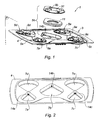
- FIG. 1 shows a cooking unit 1 according to the invention.
- this cooking set 1 comprises a cooking plate 3 itself comprising a plurality of receptacles 5a to 5e interconnected by a plate 4, each of these receptacles comprising a bowl 7a to 7c and a cover 9a to 9e.
- each of the bowls 7a to 7c is a flame burner internal 11, only one of these burners being visible in Figure 1, in the output position of its associated bowl 7b.
- FIG. 2 shows that the plate of 3 can be formed by a sheet metal plate 4 stamped so as to form a plurality of cuvettes 7a to 7e each preferably having a shape "in part of cake ".
- these cuvettes can be manufactured independently others, and reported for example by welding on a sheet metal plate 4 the connecting them.
- Each bowl 7a to 7e has a gas inlet port 14a to 14c.
- FIG. 3 there is shown a view in FIG. exploded perspective of an internal flame burner 11 that can be used with the cooking plate 3 according to the invention.
- this burner 11 comprises a gas injector 15, a vacuum tube 17, a pot 19 and a cap 21.
- the vacuum tube 17, also called "venturi" has the role of ensuring a primary air induction of combustion, this induction of air, or aspiration, resulting the depression caused in the tube 17 by the gas leaving the injector 15, and accompanied by turbulence by which the primary air mixes with the gas.
- the hat 21 caps the pot 19 and delimits, together with this pot 19, a annular chamber 23 whose inner edge 25 has orifices 27 of exit of flames.
- the tube 17 extends along an axis which is substantially contained in the plane where the openings 27 open and, preferably, this tube has a length which is at most equal to twice the radius of the inner edge 25 of this chamber.
- a distribution member 29 shaped in an arc is interposed between the output of the tube 17 and those of the orifices 27 which are arranged opposite this outlet.
- a cover 9 can be used with the cooking plate according to the invention.
- this cover 9 comprises a central opening 31 of flame outlet, this opening being at the bottom of a frustoconical portion 33 around which are distributed several, for example four, tabs 35a to 35d of container support.
- the general shape of the cover 9 corresponds to that of the cuvettes 7a to 7d (see Figure 2).
- the burner 11 shown in this figure has a shape slightly different from the one just described: the invention is indeed not limited to a specific model of internal flame burner.
- FIG. 5 shows that the vacuum tube 17 is disposed in the extension of the gas injector 15, itself arranged in the inlet orifice of gas 14 of the bowl 7.
- the burner 11 is simply placed on the bottom of the bowl 7.
- Space E is obtained by any appropriate means, such as wedges (no represented) interposed between the cover 9 and the plate 4.
- the chimney 37 of the burner that is to say the region of the burner on which the flame outlet openings 27 open, is disposed at right of the central opening 31 of the lid 9.
- this central opening 31 is arranged under the tray 4 of the hob 3.
- edge 39 of this central opening is curved on itself, so as to have a form of flame deflector.
- the lid 9 forms, with the bowl 7, a quasi-closed volume towards the interior which one can perfectly control the incoming airflow A.
- the space E can be calibrated so that the air flow A to optimize the energy efficiency of the burner 11, which uses a part A1 of this air as primary air (directly mixed with incoming gas the injector 15), and another part A2 of this air as a secondary air (incorporated in combustion in the chimney area 37).
- the frustoconical shape of the cover 9 allows to lower the level of the bottom of the container to be heated with respect to the plate 4, which goes in the direction of a smaller vertical footprint and is particularly interesting from an aesthetic point of view.
- the curved shape of the edge 39 of the opening 31 allows to favor the distribution of the flames under the container to be heated: thanks to this form indeed, the flames are first directed towards the center of the chimney 37, then bend up and out of the burner.
- covers 9a to 9e also makes it possible to protect burners and bowls from dirt that may be heat.
- the cooking assembly according to the invention could be limited to a cooktop consisting of a single bowl and a single burner.
- the cooking assembly according to the invention could include a "collective" bowl and / or lid, that is, receiving and / or covering respectively several burners.
Landscapes
- Engineering & Computer Science (AREA)
- Chemical & Material Sciences (AREA)
- Combustion & Propulsion (AREA)
- Mechanical Engineering (AREA)
- General Engineering & Computer Science (AREA)
- Gas Burners (AREA)
Abstract
Description
La présente invention se rapporte à un réceptacle pour brûleur à gaz à flamme interne, et à un ensemble de cuisson comprenant un tel réceptacle et un tel brûleur.The present invention relates to a receptacle for a gas burner flame, and to a cooking assembly comprising such a receptacle and such burner.
On connaít de la technique antérieure des brûleurs à gaz à flamme interne, c'est-à-dire des brûleurs comprenant un partie creuse centrale appelée couramment « cheminée », de laquelle sortent les flammes permettant de chauffer des récipients tels que des casseroles de cuisine.It is known from the prior art internal flame gas burners, that is to say burners comprising a central hollow part commonly called "Chimney", from which flames for heating containers such as cooking pans.
Ces brûleurs, qui se distinguent des classiques brûleurs à gaz à flamme périphérique équipant les cuisinières traditionnelles, sont en général réputés pour leurs meilleurs performances énergétiques : pour une même quantité de gaz fournie en entrée, on réussit à chauffer de manière plus rapide le contenu d'un récipient.These burners, which are distinguished from conventional flame gas burners devices used in traditional cooking ranges, are generally known for their best energy performance: for the same quantity of gas supplied at the inlet, it is possible to heat the contents of a container more rapidly.
Sans que cela prétende être exhaustif, on pourra trouver des exemples de brûleurs à gaz à flamme interne dans les brevets FR 01 15643 au nom d'A.E.M., FR 02 16041 au nom de Gaz de France, et JP 10 19425 au nom de RINNAI KK.Without pretending to be exhaustive, we can find examples of internal flame gas burners in FR 01 15643 in the name of A.E.M., FR 02 16041 in the name of Gaz de France, and JP 10 19425 in the name of RINNAI KK.
La présente invention a notamment pour but de fournir des moyens permettant d'améliorer encore les performances énergétiques des brûleurs à gaz à flamme interne.The present invention is intended in particular to provide means to further improve the energy performance of gas burners internal flame.
On atteint ce but de l'invention avec un réceptacle pour brûleur à gaz à
flamme interne, remarquable en ce qu'il comprend :
Ce réceptacle selon l'invention permet d'enfermer un brûleur à gaz à flamme interne dans un volume dont on contrôle parfaitement les arrivées d'air.This receptacle according to the invention makes it possible to enclose a flame gas burner internal in a volume which one controls perfectly the air inlets.
On peut en particulier calibrer ces arrivées d'air de manière à optimiser le processus de combustion qui se déroule au sein du brûleur, et ainsi optimiser les performances de ce brûleur.In particular, these air inlets can be calibrated in such a way as to optimize the combustion process that takes place within the burner, and thus optimize the performance of this burner.
Suivant d'autres caractéristiques de ce réceptacle :
- ledit couvercle présente une forme de déflecteur de flamme,
- ledit couvercle présente une région tronconique au fond de laquelle se trouve ladite ouverture,
- ledit couvercle comporte des pattes de support de récipients,
- said cover has a form of flame deflector,
- said lid has a frustoconical region at the bottom of which is said opening,
- said lid comprises container support tabs,
La présente invention se rapporte également à une plaque de cuisson, remarquable en ce qu'elle comprend au moins un réceptacle conforme à ce qui précède et un plateau relié de manière étanche au bord de ladite cuvette.The present invention also relates to a hob, remarkable in that it comprises at least one receptacle conforming to precedes and a plate sealingly connected to the edge of said bowl.
Suivant d'autres caractéristiques de cette plaque de cuisson, ladite ouverture est disposée sous ledit plateau.According to other characteristics of this cooking plate, said opening is disposed under said tray.
La présente invention se rapporte également à un ensemble de cuisson, remarquable en ce qu'il comprend une plaque de cuisson conforme à ce qui précède et au moins un brûleur à flamme interne disposé dans ledit réceptacle, et dont l'injecteur communique avec ledit orifice d'arrivée de gaz et dont la cheminée est disposée au droit de ladite ouverture.The present invention also relates to a cooking assembly, remarkable in that it includes a hob according to the foregoing and at least one internal flame burner disposed in said receptacle, and the injector communicates with said gas inlet and whose chimney is disposed at the right of said opening.
Suivant d'autres caractéristiques de cet ensemble de cuisson ;
- ledit brûleur à gaz est du type compact,
- ledit brûleur comporte un tube à dépression situé sensiblement dans le plan où débouchent les orifices de sortie de flammes dudit brûleur,
- ledit brûleur comprend une pluralité de réceptacles et de brûleurs de tailles différentes.
- said gas burner is of the compact type,
- said burner comprises a vacuum tube located substantially in the plane where the flame outlet openings of said burner open,
- said burner comprises a plurality of receptacles and burners of different sizes.
D'autres caractéristiques et avantages de la présente invention apparaítront à la lumière de la description qui va suivre et à l'examen des planches de dessin annexées, dans lesquelles :
- la figure 1 est une vue en perspective éclatée d'un ensemble de cuisson selon l'invention,
- la figure 2 est une vue en perspective d'une plaque de cuisson faisant partie de l'ensemble de cuisson de la figure 1,
- la figure 3 est une vue en perspective éclatée d'un des brûleurs faisant partie de l'ensemble de cuisson de la figure 1,
- la figure 4 est une vue en perspective d'un des couvercles faisant partie de l'ensemble de cuisson de la figure 1, et
- la figure 5 est une vue en coupe selon le plan P de la figure 1 d'une partie de l'ensemble de cuisson de cette figure.
- FIG. 1 is an exploded perspective view of a cooking assembly according to the invention,
- FIG. 2 is a perspective view of a cooking plate forming part of the cooking assembly of FIG. 1,
- FIG. 3 is an exploded perspective view of one of the burners forming part of the cooking assembly of FIG. 1,
- FIG. 4 is a perspective view of one of the lids forming part of the cooking assembly of FIG. 1, and
- Figure 5 is a sectional view along the plane P of Figure 1 of a portion of the cooking assembly of this figure.
On se reporte à présent à la figure 1, sur laquelle on a représenté un ensemble de cuisson 1 selon l'invention. Referring now to FIG. 1, which shows a cooking unit 1 according to the invention.
Comme on peut le voir sur cette figure, cet ensemble de cuisson 1 comprend
une plaque de cuisson 3 comprenant elle-même une pluralité de réceptacles 5a à 5e
reliés entre eux par un plateau 4, chacun de ces réceptacles comprenant une cuvette
7a à 7c et un couvercle 9a à 9e.As can be seen in this figure, this cooking set 1 comprises
a
A l'intérieur de chacune des cuvettes 7a à 7c se trouve un brûleur à flamme
interne 11, un seul de ces brûleurs étant visible sur la figure 1, en position sortie de
sa cuvette associée 7b.Inside each of the
On se reporte à présent à la figure 2, sur laquelle on voit que la plaque de
cuisson 3 peut être formée par une plaque de tôle 4 emboutie de manière à former
une pluralité de cuvettes 7a à 7e ayant de préférence chacune une forme « en part
de gâteau ».Referring now to FIG. 2, which shows that the plate of
3 can be formed by a
En variante, ces cuvettes peuvent être fabriquées indépendamment les unes
des autres, et rapportées par exemple par soudage sur une plaque de tôle 4 les
reliant entre elles.Alternatively, these cuvettes can be manufactured independently
others, and reported for example by welding on a
Chaque cuvette 7a à 7e comporte un orifice d'arrivée de gaz 14a à 14c.Each
On se reporte à présent à la figure 3, sur laquelle on a représenté une vue en
perspective éclatée d'un brûleur à flamme interne 11 pouvant être utilisé avec la
plaque de cuisson 3 selon l'invention.Referring now to FIG. 3, there is shown a view in FIG.
exploded perspective of an
Ce brûleur est conforme à celui de l'enseignement de la demande de brevet FR 02 16041, mais il faut bien comprendre que cet exemple n'est nullement limitatif.This burner is consistent with that of the teaching of the patent application FR 02 16041, but it should be understood that this example is not limiting.
On rappelle ici rapidement que ce brûleur 11 comporte un injecteur de gaz
15, un tube à dépression 17, un pot 19 et un chapeau 21.It is quickly recalled here that this
Le tube à dépression 17, encore appelé « venturi », a pour rôle d'assurer une
induction d'air primaire de combustion, cette induction d'air, ou aspiration, résultant
de la dépression provoquée dans le tube 17 par le gaz sortant de l'injecteur 15, et
s'accompagnant de turbulences grâce auxquelles l'air primaire se mélange au gaz.The
Le chapeau 21 coiffe le pot 19 et délimite, conjointement avec ce pot 19, une
chambre annulaire 23 dont le bord interne 25 présente des orifices 27 de sortie de
flammes.The
L'air et le gaz en provenance du tube 17 finissent par se mélanger de façon
intime dans cette chambre 23, le mélange combustible qui en résulte se répartissant
de façon homogène et étant distribué vers les orifices 27 de sortie de flammes, où il
est enflammé et brûle avec un apport d'air secondaire environnant. The air and gas from
Le tube 17 s'étend suivant un axe qui est sensiblement contenu dans le plan
où débouchent les orifices 27 et, de préférence, ce tube présente une longueur qui
est au plus égale au double du rayon du bord interne 25 de cette chambre.The
Du fait de ce rapport de longueur, un tel brûleur présente un faible encombrement dans la direction horizontale, et peut ainsi être qualifié de « compact ».Because of this length ratio, such a burner has a low congestion in the horizontal direction, and can thus be described as "Compact".
Un organe de répartition 29 conformé en arc de cercle est interposé entre la
sortie du tube 17 et ceux des orifices 27 qui sont disposés en regard de cette sortie.A
On se reporte à présent à la figure 4, sur laquelle on a représenté un
couvercle 9 pouvant être utilisé avec la plaque de cuisson selon l'invention.Referring now to FIG. 4, there is shown a
Comme cela est visible sur cette figure, ce couvercle 9 comprend une
ouverture centrale 31 de sortie de flammes, cette ouverture se trouvant au fond d'une
partie tronconique 33 autour de laquelle sont réparties plusieurs, par exemple quatre,
pattes 35a à 35d de support de récipient.As can be seen in this figure, this
On remarquera que la forme générale du couvercle 9 correspond à celle des
cuvettes 7a à 7d (voir figure 2).It will be noted that the general shape of the
L'ensemble des organes qui viennent d'être décrits peuvent être fabriqués en acier inoxydable ou autre alliage analogue.All the organs that have just been described can be manufactured in stainless steel or other similar alloy.
On se reporte à présent à la figure 5, sur laquelle on voit le manière dont une
cuvette 7, un brûleur à flamme interne 11 et un couvercle 9 sont agencés les uns
relativement aux autres en situation opérationnelle.We now turn to Figure 5, where we see how a
7, an
On notera que le brûleur 11 représenté sur cette figure présente une forme
légèrement différente de celui qui vient d'être décrit : l'invention n'est en effet
nullement limitée à un modèle précis de brûleur à flamme interne.Note that the
On voit sur la figure 5 que le tube à dépression 17 est disposé dans le
prolongement de l'injecteur de gaz 15, lui-même disposé dans l'orifice d'arrivée de
gaz 14 de la cuvette 7.FIG. 5 shows that the
Le brûleur 11 est simplement posé sur le fond de la cuvette 7.The
On voit qu'un espace E est ménagé entre la périphérie du couvercle 9 et le
plateau 4, permettant à de l'air A de circuler de l'extérieur vers l'intérieur de la cuvette
7.We see that a space E is formed between the periphery of the
L'espace E est obtenu par tout moyen approprié, tel que des cales (non
représentées) interposées entre le couvercle 9 et le plateau 4. Space E is obtained by any appropriate means, such as wedges (no
represented) interposed between the
On voit également que la cheminée 37 du brûleur 11, c'est-à-dire la région du
brûleur sur laquelle débouchent les orifices de sortie de flammes 27, est disposée au
droit de l'ouverture centrale 31 du couvercle 9.It can also be seen that the
On voit également que cette ouverture centrale 31 est disposée sous le
plateau 4 de la plaque de cuisson 3.We also see that this
On voit encore que le bord 39 de cette ouverture centrale est recourbé sur lui-même,
de manière à présenter une forme de déflecteur de flamme.It can still be seen that the
Le mode de fonctionnement et les avantages de l'invention résultent directement de la description qui précède.The mode of operation and the advantages of the invention result directly from the foregoing description.
On se réfère tout particulièrement à la figure 5.Reference is particularly made to FIG.
Le couvercle 9 forme, avec la cuvette 7, un volume quasi-clos vers l'intérieur
duquel on peut parfaitement contrôler le flux d'air entrant A.The
On peut en particulier calibrer l'espace E de manière que le flux d'air A
permette d'optimiser le rendement énergétique du brûleur 11, lequel utilise une partie
A1 de cet air en tant qu'air primaire (directement mélangé au gaz arrivant par
l'injecteur 15), et une autre partie A2 de cet air en tant qu'air secondaire (incorporé à
la combustion dans la zone de la cheminée 37).In particular, the space E can be calibrated so that the air flow A
to optimize the energy efficiency of the
On peut ainsi, en particulier, doser l'air A de manière à réduire les imbrûlés.It is thus possible, in particular, to dose the air A so as to reduce the unburnt.
On notera par ailleurs que la forme tronconique du couvercle 9 permet
d'abaisser le niveau du fond du récipient à chauffer par rapport au plateau 4, ce qui
va dans le sens d'un moindre encombrement vertical et est particulièrement
intéressant d'un point de vue esthétique.Note also that the frustoconical shape of the
On notera en particulier qu'on peut rendre les brûleurs pratiquement invisibles de l'extérieur, ce qui permet d'obtenir un design très sobre.Note in particular that we can make the burners virtually invisible from the outside, which allows to obtain a very sober design.
On notera qu'en utilisant un brûleur à flamme interne tel que celui représenté
sur les figures, c'est-à-dire du type présentant un tube à dépression 17 situé
sensiblement dans le plan où débouchent les orifices 27 de sortie de flammes, on
peut obtenir un ensemble de cuisson ultra-plat.Note that using an internal flame burner such as the one shown
in the figures, that is to say of the type having a
On notera également que la forme recourbée du bord 39 de l'ouverture 31
permet de favoriser la répartition des flammes sous le récipient à chauffer : grâce à
cette forme en effet, les flammes sont tout d'abord dirigées vers le centre de la
cheminée 37, puis s'infléchissent vers le haut et l'extérieur du brûleur.Note also that the curved shape of the
On notera que la présence des couvercles 9a à 9e permet en outre de
protéger les brûleurs et les cuvettes des souillures pouvant provenir des récipients à
chauffer. It will be noted that the presence of the
On notera que le fait de puiser au-dessus de la table de cuisson la totalité de l'air nécessaire à la combustion permet de respecter les normes en vigueur.It should be noted that the fact of drawing above the hob the whole of the air required for combustion makes it possible to comply with the standards in force.
Le fait de rendre étanche la liaison des cuvettes 7a à 7e au plateau 4 permet
d'éviter tout confinement accidentel de gaz sous la table de cuisson.The sealing of the connection of the
Bien entendu, la présente invention n'est pas limitée au mode de réalisation décrit et représenté.Of course, the present invention is not limited to the embodiment described and represented.
C'est ainsi par exemple que l'ensemble de cuisson selon l'invention pourrait être limité à une plaque de cuisson comprenant une seule cuvette et un seul brûleur.For example, the cooking assembly according to the invention could be limited to a cooktop consisting of a single bowl and a single burner.
C'est ainsi également que l'ensemble de cuisson selon l'invention pourrait comprendre une cuvette et/ou un couvercle « collectifs », c'est-à-dire recevant et/ou couvrant respectivement plusieurs brûleurs.It is thus also that the cooking assembly according to the invention could include a "collective" bowl and / or lid, that is, receiving and / or covering respectively several burners.
Claims (10)
Applications Claiming Priority (2)
| Application Number | Priority Date | Filing Date | Title |
|---|---|---|---|
| FR0309442A FR2858393B1 (en) | 2003-07-31 | 2003-07-31 | RECEPTACLE FOR INTERNAL FLAME GAS BURNER AND COOKING ASSEMBLY COMPRISING SUCH RECEPTACLE AND BURNER |
| FR0309442 | 2003-07-31 |
Publications (1)
| Publication Number | Publication Date |
|---|---|
| EP1503146A1 true EP1503146A1 (en) | 2005-02-02 |
Family
ID=33523031
Family Applications (1)
| Application Number | Title | Priority Date | Filing Date |
|---|---|---|---|
| EP04291942A Withdrawn EP1503146A1 (en) | 2003-07-31 | 2004-07-29 | Compartment for gas burner with internal flame, and cooking unit comprising such a compartment and such a burner |
Country Status (4)
| Country | Link |
|---|---|
| US (1) | US20050026098A1 (en) |
| EP (1) | EP1503146A1 (en) |
| CA (1) | CA2475291A1 (en) |
| FR (1) | FR2858393B1 (en) |
Cited By (1)
| Publication number | Priority date | Publication date | Assignee | Title |
|---|---|---|---|---|
| EP3045811A1 (en) * | 2015-01-13 | 2016-07-20 | LG Electronics Inc. | Cooking appliance and gas burner |
Citations (2)
| Publication number | Priority date | Publication date | Assignee | Title |
|---|---|---|---|---|
| EP0534301A2 (en) * | 1991-09-26 | 1993-03-31 | MERLONI ELETTRODOMESTICI S.p.A. | Gas burner for food cooking |
| WO1999011975A1 (en) * | 1997-08-28 | 1999-03-11 | Aktiebolaget Electrolux | A gas hotplate burner |
Family Cites Families (5)
| Publication number | Priority date | Publication date | Assignee | Title |
|---|---|---|---|---|
| US3625196A (en) * | 1970-05-05 | 1971-12-07 | W J Schoenberger Co The | Burner cap assembly |
| US5437262A (en) * | 1994-02-17 | 1995-08-01 | Gas Research Institute | Burner apparatus |
| JPH1019425A (en) | 1996-06-28 | 1998-01-23 | Hitachi Ltd | Refrigerating machine oil/refrigerant separator |
| FR2804496B1 (en) * | 2000-01-28 | 2002-07-19 | Sourdillon Sa | MULTIPLE FLAME CROWN GAS BURNER |
| IT1315325B1 (en) * | 2000-04-28 | 2003-02-10 | Paolo Moresco | GAS BURNER FOR HOB |
-
2003
- 2003-07-31 FR FR0309442A patent/FR2858393B1/en not_active Expired - Fee Related
-
2004
- 2004-07-16 CA CA002475291A patent/CA2475291A1/en not_active Abandoned
- 2004-07-29 US US10/901,194 patent/US20050026098A1/en not_active Abandoned
- 2004-07-29 EP EP04291942A patent/EP1503146A1/en not_active Withdrawn
Patent Citations (2)
| Publication number | Priority date | Publication date | Assignee | Title |
|---|---|---|---|---|
| EP0534301A2 (en) * | 1991-09-26 | 1993-03-31 | MERLONI ELETTRODOMESTICI S.p.A. | Gas burner for food cooking |
| WO1999011975A1 (en) * | 1997-08-28 | 1999-03-11 | Aktiebolaget Electrolux | A gas hotplate burner |
Cited By (2)
| Publication number | Priority date | Publication date | Assignee | Title |
|---|---|---|---|---|
| EP3045811A1 (en) * | 2015-01-13 | 2016-07-20 | LG Electronics Inc. | Cooking appliance and gas burner |
| US10502428B2 (en) | 2015-01-13 | 2019-12-10 | Lg Electronics Inc. | Cooking appliance and gas burner |
Also Published As
| Publication number | Publication date |
|---|---|
| FR2858393B1 (en) | 2005-09-30 |
| FR2858393A1 (en) | 2005-02-04 |
| US20050026098A1 (en) | 2005-02-03 |
| CA2475291A1 (en) | 2005-01-31 |
Similar Documents
| Publication | Publication Date | Title |
|---|---|---|
| EP1431658B1 (en) | Compact gas burner with internal flame | |
| FR2804496A1 (en) | MULTIPLE FLAME CROWN GAS BURNER | |
| EP2134221B1 (en) | Apparatus for the steam preparation of foodstuffs | |
| EP1306616A1 (en) | Gas burner of the atmospheric type | |
| FR2650369A1 (en) | Gas burner for cooking food | |
| CA2893432A1 (en) | Gas burner comprising a burner heat | |
| EP1640663A2 (en) | Improved gas burner with only internal flame | |
| FR2697320A1 (en) | Extra-flat gas burner with safety system intended particularly for cooking appliances for domestic use. | |
| BE902029A (en) | GAS BURNER FOR FURNACES AND COOKING PLATES IN GENERAL. | |
| FR2736143A1 (en) | BURNER APPARATUS CENTERED ON AN INJECTOR. | |
| EP1503146A1 (en) | Compartment for gas burner with internal flame, and cooking unit comprising such a compartment and such a burner | |
| EP1099905B1 (en) | Household cooking hob gas burner | |
| FR2783040A1 (en) | GAS BURNER FOR HEATING AND / OR COOKING FOOD | |
| CA3146685A1 (en) | Modular burner and furnace comprising this burner | |
| EP2216595A2 (en) | Gas burner | |
| EP0491580B1 (en) | Gas burner for cooking range, cooking top or the like | |
| EP1412678A1 (en) | Forced convection gas oven | |
| EP0719987A1 (en) | Gas cooker | |
| FR2693256A1 (en) | Flat gas hob - has separating plate between grill and recovery table with secondary air opening centred on each burner | |
| EP0611920B1 (en) | Gasburner for cooking apparatus comprising three parts and a pilot flame | |
| EP0669498B1 (en) | Combustion apparatus for solid or liquid fuel | |
| BE1022948B1 (en) | HEATING APPARATUS WITH MINI BURNERS | |
| FR3114735A1 (en) | Food cooking device | |
| FR2833071A1 (en) | Multi-use gas burner, especially for cooking surface, has head with gas mixture passages angled to create turbulence in central zone | |
| EP1172607A1 (en) | Gas burner with increased power |
Legal Events
| Date | Code | Title | Description |
|---|---|---|---|
| PUAI | Public reference made under article 153(3) epc to a published international application that has entered the european phase |
Free format text: ORIGINAL CODE: 0009012 |
|
| AK | Designated contracting states |
Kind code of ref document: A1 Designated state(s): AT BE BG CH CY CZ DE DK EE ES FI FR GB GR HU IE IT LI LU MC NL PL PT RO SE SI SK TR |
|
| AX | Request for extension of the european patent |
Extension state: AL HR LT LV MK |
|
| 17P | Request for examination filed |
Effective date: 20050722 |
|
| AKX | Designation fees paid |
Designated state(s): AT BE BG CH CY CZ DE DK EE ES FI FR GB GR HU IE IT LI LU MC NL PL PT RO SE SI SK TR |
|
| 17Q | First examination report despatched |
Effective date: 20081107 |
|
| STAA | Information on the status of an ep patent application or granted ep patent |
Free format text: STATUS: THE APPLICATION IS DEEMED TO BE WITHDRAWN |
|
| 18D | Application deemed to be withdrawn |
Effective date: 20091121 |