EP1503142B1 - Verfahren zum Betrieb eines Kombikraftwerks mit einer Kohlevergasungsanlage - Google Patents
Verfahren zum Betrieb eines Kombikraftwerks mit einer Kohlevergasungsanlage Download PDFInfo
- Publication number
- EP1503142B1 EP1503142B1 EP04023944A EP04023944A EP1503142B1 EP 1503142 B1 EP1503142 B1 EP 1503142B1 EP 04023944 A EP04023944 A EP 04023944A EP 04023944 A EP04023944 A EP 04023944A EP 1503142 B1 EP1503142 B1 EP 1503142B1
- Authority
- EP
- European Patent Office
- Prior art keywords
- fuel
- coal gasification
- combustor
- combustion
- gas turbine
- Prior art date
- Legal status (The legal status is an assumption and is not a legal conclusion. Google has not performed a legal analysis and makes no representation as to the accuracy of the status listed.)
- Expired - Lifetime
Links
Images




Classifications
-
- F—MECHANICAL ENGINEERING; LIGHTING; HEATING; WEAPONS; BLASTING
- F02—COMBUSTION ENGINES; HOT-GAS OR COMBUSTION-PRODUCT ENGINE PLANTS
- F02C—GAS-TURBINE PLANTS; AIR INTAKES FOR JET-PROPULSION PLANTS; CONTROLLING FUEL SUPPLY IN AIR-BREATHING JET-PROPULSION PLANTS
- F02C3/00—Gas-turbine plants characterised by the use of combustion products as the working fluid
- F02C3/20—Gas-turbine plants characterised by the use of combustion products as the working fluid using a special fuel, oxidant, or dilution fluid to generate the combustion products
- F02C3/26—Gas-turbine plants characterised by the use of combustion products as the working fluid using a special fuel, oxidant, or dilution fluid to generate the combustion products the fuel or oxidant being solid or pulverulent, e.g. in slurry or suspension
- F02C3/28—Gas-turbine plants characterised by the use of combustion products as the working fluid using a special fuel, oxidant, or dilution fluid to generate the combustion products the fuel or oxidant being solid or pulverulent, e.g. in slurry or suspension using a separate gas producer for gasifying the fuel before combustion
-
- F—MECHANICAL ENGINEERING; LIGHTING; HEATING; WEAPONS; BLASTING
- F23—COMBUSTION APPARATUS; COMBUSTION PROCESSES
- F23D—BURNERS
- F23D17/00—Burners for combustion simultaneously or alternately of gaseous or liquid or pulverulent fuel
- F23D17/002—Burners for combustion simultaneously or alternately of gaseous or liquid or pulverulent fuel gaseous or liquid fuel
-
- F—MECHANICAL ENGINEERING; LIGHTING; HEATING; WEAPONS; BLASTING
- F23—COMBUSTION APPARATUS; COMBUSTION PROCESSES
- F23R—GENERATING COMBUSTION PRODUCTS OF HIGH PRESSURE OR HIGH VELOCITY, e.g. GAS-TURBINE COMBUSTION CHAMBERS
- F23R3/00—Continuous combustion chambers using liquid or gaseous fuel
- F23R3/28—Continuous combustion chambers using liquid or gaseous fuel characterised by the fuel supply
- F23R3/36—Supply of different fuels
-
- F—MECHANICAL ENGINEERING; LIGHTING; HEATING; WEAPONS; BLASTING
- F23—COMBUSTION APPARATUS; COMBUSTION PROCESSES
- F23R—GENERATING COMBUSTION PRODUCTS OF HIGH PRESSURE OR HIGH VELOCITY, e.g. GAS-TURBINE COMBUSTION CHAMBERS
- F23R2900/00—Special features of, or arrangements for continuous combustion chambers; Combustion processes therefor
- F23R2900/00002—Gas turbine combustors adapted for fuels having low heating value [LHV]
-
- Y—GENERAL TAGGING OF NEW TECHNOLOGICAL DEVELOPMENTS; GENERAL TAGGING OF CROSS-SECTIONAL TECHNOLOGIES SPANNING OVER SEVERAL SECTIONS OF THE IPC; TECHNICAL SUBJECTS COVERED BY FORMER USPC CROSS-REFERENCE ART COLLECTIONS [XRACs] AND DIGESTS
- Y02—TECHNOLOGIES OR APPLICATIONS FOR MITIGATION OR ADAPTATION AGAINST CLIMATE CHANGE
- Y02E—REDUCTION OF GREENHOUSE GAS [GHG] EMISSIONS, RELATED TO ENERGY GENERATION, TRANSMISSION OR DISTRIBUTION
- Y02E20/00—Combustion technologies with mitigation potential
- Y02E20/16—Combined cycle power plant [CCPP], or combined cycle gas turbine [CCGT]
-
- Y—GENERAL TAGGING OF NEW TECHNOLOGICAL DEVELOPMENTS; GENERAL TAGGING OF CROSS-SECTIONAL TECHNOLOGIES SPANNING OVER SEVERAL SECTIONS OF THE IPC; TECHNICAL SUBJECTS COVERED BY FORMER USPC CROSS-REFERENCE ART COLLECTIONS [XRACs] AND DIGESTS
- Y02—TECHNOLOGIES OR APPLICATIONS FOR MITIGATION OR ADAPTATION AGAINST CLIMATE CHANGE
- Y02E—REDUCTION OF GREENHOUSE GAS [GHG] EMISSIONS, RELATED TO ENERGY GENERATION, TRANSMISSION OR DISTRIBUTION
- Y02E20/00—Combustion technologies with mitigation potential
- Y02E20/16—Combined cycle power plant [CCPP], or combined cycle gas turbine [CCGT]
- Y02E20/18—Integrated gasification combined cycle [IGCC], e.g. combined with carbon capture and storage [CCS]
Definitions
- the present invention relates to an operating method for a coal gasification combined cycle power generation plant or facility which selectively burns a coal gasification fuel and a liquid fuel so as to generate a power, particularly for suitably preventing a combustion gas from conversely flowing into a fuel passage of a coal gasification fuel when using a liquid fuel and for improving a safety in a combustor section.
- a coal gasification fuel is generated from coal by a coal gasification furnace with the use of an air compressed by a gas turbine compressor or oxygen generated by leading the air to an air separator.
- the coal gasification fuel thus generated is supplied to a gas turbine combustor so as to be burned, and then, by the generated combustion gas, a gas turbine is driven to generate a power.
- the coal gasification fuel has a worse combustibility as compared with a liquid fuel or a natural gas fuel and has a small calorific value. Further, in the case where a combustion gas temperature in the combustor becomes low, a lot of carbon monoxide is discharged, thus providing a problem in operational characteristics during a low load operation. Therefore, it is desirable to employ a combined cycle facility for compensating the defect of coal gasification fuel by burning other fuels during a starting operation or a low load operation. In such viewpoint, a liquid fuel has been employed as other fuel used in the combined cycle plant.
- the coal gasification combined cycle equipment includes a combustor which can selectively burn a coal gasification fuel gasified coal and a liquid fuel atomized by an atomization air and is constructed in a manner that a combustion gas generated by the combustor is supplied to a gas turbine so that a generator is driven by a power of the gas turbine.
- the liquid fuel is supplied to the combustor to be burned, and thereby, the gas turbine starts up.
- the gas turbine starts up a generation of coal gasification fuel is simultaneously started in a coal gasification furnace.
- an compressed air from an auxiliary compressor or oxygen separated from the compressed air by an air separator is used.
- an air compressed by a gas turbine compressor or oxygen separated from the compressed air by the air separator is used.
- the coal gasification fuel has a small calorific value as compared with a liquid fuel or a natural gas.
- a combustion gas temperature in the combustor becomes low, a lot of carbon monoxide is discharged, and therefore, there is a problem in operational characteristics during a low load operation. For this reason, in the case where the gas turbine is in a load dump state or when the gas turbine is stopped, the operation change-over is again made from the operation of using the coal gasification fuel to the operation of using only the liquid fuel.
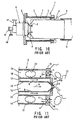
- Fig. 10 is a view schematically showing an entire structure of a combustor included in the aforesaid coal gasification combined cycle power generation plant
- Fig. 11 is an enlarge sectional view showing a fuel nozzle section of the combustor.
- a combustor 1 is constructed in a manner that a combustor liner 4 used as an inner cylindrical casing is inserted into an outer cylindrical casing 2 with a combustion air passage 3 defined therebetween, a fuel nozzle 5 is provided on an end portion on an upstream side of the combustor liner 4, and a transition piece 6 is connected to a downstream side of the combustor liner 4.
- An inner circumferential portion of the outer cylindrical casing 2 is provided with a flow sleeve 7 which covers the combustion air passage 3 and functions as an air guide.
- the fuel nozzle 5 has a multiple cylindrical structure fixed to a head plate 8 provided on the end portion of the outer cylindrical casing 2. Further, the fuel nozzle 5 is provided, at its outer end positioned on the outside thereof, with a liquid fuel supply port 9 for supplying a liquid fuel, an atomization air supply port 10 for supplying an atomization air for atomizing the liquid fuel, and a coal gasification fuel supply port 11 for supplying a coal gasification fuel.
- the fuel nozzle 5 is formed with a liquid fuel passage 12 for passing the liquid fuel at the center portion on the internal side thereof, an atomization air passage 13 for passing an atomization air of the liquid fuel at the outer side of the liquid fuel passage 12, and further, a coal gasification fuel passage 14 for passing the coal gasification fuel at the outer side of the atomization air passage 13.
- These passages 12, 13 and 14 are arranged side-by-side in a manner of being partitioned by cylindrical walls 15 and 16 and communicate with the liquid fuel supply port 9, the atomization air supply port 10 and the coal gasification fuel supply port 11, respectively.
- an inner end portion of the fuel nozzle 5 facing the inside of the combustor liner 4 is provided with a liquid fuel injection port 17 for injecting a liquid fuel "a” from the liquid fuel passage 12, an atomization air injection port 18 which injects an atomization air “b” around the liquid fuel injection port 17 from the atomization air passage 13 so that the liquid fuel "a” becomes an atomized state, and a coal gasification fuel injection port 20 having a swirler 19 which injects a coal gasification fuel "c” from the coal gasification fuel passage 14 in a rotating state.
- the coal gasification fuel "c” or the liquid fuel “a” in an air atomized state is selectively injected into the combustor 5 from the fuel nozzle 5 by a known means, and a combustion air “d” is supplied into the combustor liner 4 from a gas turbine compressor (not shown) via the combustion air passage 3 to thereby start the combustion. Then, a combustion gas 21 thus generated is supplied to a gas turbine (not shown) via the transition piece 6.
- EP 0 278 699 discloses a method and an apparatus for burning gaseous fuel, wherein the fuel composition varies, wherein the fuel is divided into a main part and a sub-part, which are then injected through main injection ports and sub-injection ports, respectively, into a combustion chamber, in which the fuel injected through the sub-injection ports is burnt by a flame produced from the fuel injected from the main injection port, said method being characterized in that the flow ratio of the main part to the sub-part is controlled so that the proportion of the fuel to be injected through the main injection ports may increase as the rate of gaseous fuel burning increases, when the composition of the gaseous fuel varies.
- US 4,726,192 relates to a dual fuel injector for a gas turbine power plant, wherein a flow of air through a duct and a passage provided in the fuel injector prevents any unburned air or combustion products from entering the gas duct.
- a gas duct surrounds a central liquid duct, and an air flow partly surrounds the gas duct.
- Patent Abstracts of Japan, vol. 012, no. 027 (M-662) of 27 January 1988 discloses a gas turbine combustion system for low calorie coal gas, wherein a low calorie coal gas supplied from a supply opening is burned in a gas combustion tube and its flame is led to a gas turbine.
- a supply tube for supplying oil for ignition is located in the center of the combustion tube.
- US 4,472,936 relates to a method and an apparatus for controlling the combustion of gasified fuel in a combustor.
- US 4,442,665 discloses a combined cycle coal gasification power plant including a coal gasifier which generates low BTU coal gas for consumption by a gas turbine, wherein the coal gas is passed through a clean-up system, which removes undesirable constituents from the coal gas, before the coal gas is applied to the gas turbine.
- An object of the present invention is to eliminate defects or drawbacks encountered in the prior art described above and to provide a method for operating a coal gasification fuel combined cycle power generation plant or facility which can prevent a combustion gas from conversely flowing into a coal gasification fuel supply passage during a liquid fuel operation and can avoid damaging of a fuel nozzle so as to stably carry out a gas turbine operation and to improve a usable life of the combustor.
- the present invention as claimed, it becomes possible to prevent the combustion gas from conversely flowing into the coal gasification fuel supply passage during the liquid fuel operation. Therefore, the fuel nozzle is prevented from being damaged, whereby the gas turbine operation can be stably carried out and the usable life of the combustor can be effectively increased.
- Fig. 1 is a system diagram showing the whole construction of a coal gasification combined cycle power generation plant which can be operated according to the present invention.
- the coal gasification combined cycle power generation plant comprises a gas turbine system 31, a fuel supply system 32, an air supply system 33 and a an exhaust gas system 34, which are broadly classified and operatively connected to each other.
- the gas turbine system 31 includes a combustor 35 which can selectively burn the coal gasification fuel “c” and the liquid fuel “a”, a gas turbine 36 which is driven by a combustion gas generated by the combustor 35, a gas turbine compressor 37 which is provided coaxially with the gas turbine 36, and a generator 38.
- the selection of the coal gasification fuel and the liquid fuel is performed by a known means under the monitoring of the liquid fuel from the combustion start time.
- the fuel supply system 32 is composed of two systems, that is, a coal gasification fuel supply system 32a and a liquid fuel supply system 32b.
- the coal gasification fuel supply system 32a includes a gasification furnace 39 for gasifying coal, and a gas refinery equipment 40 for purifying a coal gas refined by the gasification furnace 39. Further, the coal gasification fuel supply system 32a supplies the refined coal gasification fuel "c" to the combustor 35 via a coal gasification fuel pipe 41.
- the coal gasification fuel pipe 41 is provided with a flow control valve 42 which functions as a flow control unit.
- the liquid fuel supply system 32b selectively supplies the liquid fuel “a” and the atomization air “b” from a liquid fuel supply source (not shown) and a atomization air supply source (not shown), and the coal gasification fuel “c” to the combustor 35 via a liquid fuel pipe 43 and an air pipe 44.
- the air supply system 33 is a system for supplying oxygen required for coal gasification in the gasification furnace 39. Further, the air supply system 33 has an extraction pipe 45 for extracting a part of compressed air from a gas turbine compressor 37, an air separator 46 which is connected to the extraction pipe 45 and generates oxygen, and an oxygen gas compressor 48 connected to the air separator 46 via an oxygen gas pipe 47. Further, in the air supply system 33, there is provided an auxiliary compressor 49 for generating oxygen used in the gasification furnace 39 before the gas turbine compressor 37 is operated.
- the exhaust gas system 34 includes an exhaust gas pipe 50 connected to the gas turbine 36, an exhaust gas boiler 51 connected to the exhaust gas pipe 50 and a chimney stack 52.
- the liquid fuel "a” and the atomization air "b" are supplied to the combustor 35 to make combustion, and thereby, the gas turbine 36 starts up.
- the coal gasification fuel is generated in the gasification furnace 39.
- a compressed air from the auxiliary compressor 49 or oxygen separated from the compressed air by the air separator 46 is used.
- the pressurized air by the gas turbine compressor 37 or oxygen separated from the pressurised air by the air separator 46 is used.
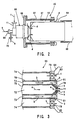
- a combustor 35 is constructed in a manner that a combustor liner 64 used as an inner cylindrical casing is inserted into an outer cylindrical casing 62 with a combustion air passage 63 defined therebetween, a fuel nozzle 65 is provided at an end portion on an upstream side of the combustor liner 64, and a transition piece 66 is connected to a downstream side of the combustor liner 64.
- An inner circumferential portion of the outer cylindrical casing 62 is provided with a flow sleeve 67 which covers the combustion air passage 63 and functions as an air guide.
- the fuel nozzle 65 has a multiple cylindrical shape fixed to a head plate 68 provided on the end portion of the outer cylindrical casing 62. Further, the fuel nozzle 65 is provided with a liquid fuel supply port 69 for supplying a liquid fuel "a”, an atomization air supply port 70 for supplying an atomization air for atomizing the liquid fuel "a”, and a coal gasification fuel supply port 71 for supplying a coal gasification fuel "c", at its outer end situated on the outer side of the outer cylindrical casing 62.
- the fuel nozzle 65 is formed with a liquid fuel passage 72 for passing the liquid fuel "a" at the center portion on the internal side thereof, an atomization air passage 73 for passing an atomization air "b" of the liquid fuel at the outer side of the liquid fuel passage 72, and further, a coal gasification fuel passage 74 for passing the coal gasification fuel "c" at the outer side of the atomization air passage 73.
- These passages 72, 73 and 74 are arranged side-by-side in a manner of being partitioned by cylindrical walls 75 and 76 and communicate with the liquid fuel supply port 69, the atomization air supply port 70 and the coal gasification fuel supply port 71, respectively.
- an inner end portion of the fuel nozzle 65 facing the inside of the combustor liner 64 is provided with a liquid fuel injection port 77 for injecting the liquid fuel "a” from the liquid fuel passage 72, an atomization air injection port 78 which injects the atomization air "b” around the liquid fuel injection port 77 from the atomization air passage 73 so that the liquid fuel "a” becomes an atomized state, and a coal gasification fuel injection port 80 having a swirler 79 which injects the coal gasification fuel "c” from the coal gasification fuel passage 74 in a rotating state.
- the fuel nozzle 65 for injecting a fuel to the combustor 35 is provided with the liquid fuel passage 72, the atomization air passage 73 and the coal gasification fuel passage 74, which are arranged so as to be adjacent to each other.
- a branching outlet port 81 for injecting the atomization air "b" toward the coal gasification injection port 80 situated on the outside is provided at a position of the injection port 78 which is an outlet portion of the atomization air passage 73.
- a plurality of the branching outlet ports 81 for the atomization air are formed along a circumferential direction of the fuel nozzle 65 and continuously inject the atomization air "b" toward the outside of the swirler 79 of the coal gasification fuel injection port 80 so that an air film is formed on the coal gasification fuel injection port 80.
- Fig. 4 is an enlarged sectional view showing a fuel nozzle 65 of a combustor 35 of said coal gasification combined cycle power generation plant.
- the fuel nozzle 65 for injection a fuel to the combustor 35 is provided with a liquid fuel passage 72, an atomization air passage 73 and a coal gasification fuel passage 74, which are arranged so as to be adjacent to each other. Further, the fuel nozzle 65 is provided with a blowout hole 82 for blowing out the atomization air to the coal gasification fuel passage 74 at a passage wall 76 in the vicinity of the outlet portion of the atomization air passage 73. A plurality of the blowout holes 82 for atomization air are formed along the circumferential direction of the fuel nozzle 65 and are individually opened in the vicinity of the coal gasification fuel passage injection port 80.
- the atomization air is continuously blown out toward the inner surface of the swirler 79, and thereafter, the atomization air "b" is injected from the coal gasification fuel outlet port 80 into the combustor liner 64.
- the other construction is substantially same as mentioned above, and therefore, the same reference numbers are used to designate the portions corresponding to those shown in Fig. 3 , and the details thereof are omitted herein.
- Fig. 5 is an enlarged sectional view showing a fuel nozzle 65 of a combustor 35 of said coal gasification combined cycle power generation plant.
- a combustion air injecting portion 83 for injecting a combustion air "d" toward an outlet portion of the coal gasification fuel passage 74 is provided at an outlet portion of the combustion air passage 63 which blows the combustion air "d” from the gas turbine compressor 37 (see Fig. 1 ) into the combustor liner 64.
- the combustion air injecting portion 83 is composed of, for example, a hole 84 which is formed at an end wall 64a on the fuel nozzle 65 side of the combustor liner 64, and a guide member 85 which is disposed on the outer peripheral side of the hole 84 and projects to the inner face of the end wall 64a of the combustor liner 64.
- the combustion air is continuously injected toward the outer side of the swirler 79 of the coal gasification fuel injection port 80 so that an air film is formed in the coal gasification fuel port 80.
- Fig. 6 is an enlarged sectional view showing a combustor 35 of said coal gasification combined cycle power generation plant.
- a combustion air injecting portion 86 for injecting a combustion air "d" toward an outlet portion of the coal gasification fuel passage 74 is provided at an outlet portion of the combustion air passage 63 which blows the combustion air "d” from the gas turbine compressor 37 into the combustor liner 64.
- the combustion air injecting portion 86 is constructed in a manner that the combustion air passage 63 and the coal gasification fuel passage 74 communicates with each other by means of a pipe 87 penetrating through the head plate 68, and the pipe 87 is provided with a control valve 88.
- the combustion air "d” is supplied to the coal gasification fuel passage 74 via the pipe 87 provided on the head plate 68.
- the control valve 88 is opened so that the combustion air "d” is blown into the combustor liner 64 from the coal gasification fuel passage 74 via the swirler 79.
- control valve 88 provided on the pipe 87 is closed during the coal gasification fuel operation so as to make a closed state.
- a check valve (not shown) may be used so as to prevent the combustion air from conversely flowing to the combustion air passage 63 side.
- This first embodiment shows an operating method of the coal gasification fuel combined cycle power generation plant according to the present invention.
- an incomplete coal gasification fuel is supplied to the coal gasification fuel passage, and thereby, there is provided an operating method of preventing the combustion gas from conversely flowing into the coal gasification fuel passage during the liquid fuel operation until the coal gasification fuel operation from the gas turbine start-up.
- the supply of the incomplete coal gasification fuel has been stopped during the liquid fuel operation until the gas turbine load becomes one fourth (1/4) load from the gas turbine start-up.
- the incomplete coal gasification fuel "c" is supplied from the coal gasification fuel passage to the combustor 35 via the fuel nozzle 35.
- Fig. 7 is a graph showing a fuel flow rate to explain the operating method mentioned above and taking a flow rate of liquid fuel and coal gasification fuel as an ordinate and taking a gas turbine load as an abscissa.
- the incomplete coal gasification fuel generated in the gasification furnace 39 is gradually supplied to the combustor together with a liquid fuel whose supplying flow rate gradually increases from the start-up.
- the combustion gas increases, and then, the internal pressure of the combustor liner is made high.
- the supply of incomplete coal gasification fuel is increased so that an internal pressure of the coal gasification fuel passage is made high. According to this function, it is possible to prevent the combustion gas from conversely flowing into the coal gasification fuel passage.
- the operation is changed into a coal gasification fuel operation at the time when the complete coal gasification fuel "c" is generated in the gasification furnace 39, and then, from this set time, the flow rate of the liquid fuel is gradually reduced. After that, the flow rate of the coal gasification fuel is increased until the rating load, and thereafter, the operation is carried out at a fixed flow rate.
- the fuel nozzle has no need of change in its structure. Further, only through the fuel supply control, it becomes possible to securely prevent the combustion gas from conversely flowing into the coal gasification fuel passage, as like as in the above-mentioned embodiments. Therefore, the gas turbine operation can be stably carried out, and the life of the combustor can be made long. As a result, great advantage is obtainable in both the viewpoints of operation and economics of the power generation plant or facility.
- This second embodiment shows an operating method of the coal gasification fuel power generation plant of the present invention.
- the coal gasification fuel is supplied to the combustor from the coal gasification fuel passage via the fuel nozzle.
- the fuel nozzle and the like have no need of change in their structure. Further, through only the fuel supply control, it becomes possible to securely prevent the combustion gas from conversely flowing into the coal gasification fuel passage as like as in the first embodiment. Therefore, the gas turbine operation can be stably carried out, and the life of the combustor can be made long. As a result, great advantage is obtainable in both the viewpoints of operation and economics of the power generation plant or facility.
- This third embodiment shows an operating method of the coal gasification fuel combined cycle power generation plant according to the present invention.
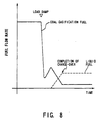
- a method of preventing the combustion gas from conversely flowing into the coal gasification fuel passage by supplying the coal gasification fuel to the coal gasification fuel passage during the liquid fuel operation in the case where a change-over is made from an operation using the coal gasification fuel into an operation using the liquid fuel during the gas turbine load dump state.
- the coal gasification fuel is supplied to the combustor from the coal gasification fuel passage via the fuel nozzle.
- Fig. 8 is a graph showing a fuel flow rate to explain the operating method, and taking a flow rate of liquid fuel and coal gasification fuel as an ordinate and taking a time as an abscissa.
- the fuel nozzle has no need of change in its structure. Further, through only the fuel supply control, it becomes possible to securely prevent the combustion gas from conversely flowing into the coal gasification fuel passage as like as in the respective embodiments mentioned above. Therefore, the gas turbine operation can be stably carried out, and the life of the combustor can be made long. As a result, great advantage is obtainable in both the viewpoints of operation and economics of the power generation plant or facility.
- This fourth embodiment shows a coal gasification combined cycle power generation plant which is preferable to the case of carrying out the operating method described with respect to the first to third embodiments and is an improvement in the coal gasification combined cycle power generation plant shown in Fig. 1 .
- a flow rate is controlled by means of the flow control valve 42 mounted to the coal gasification fuel pipe 41.
- the flow control valve 42 is provided for controlling a flow rate of the coal gasification fuel "c" during a normal operation and is constructed in a manner that the flow rate of the coal gasification fuel "c” is controlled to the 100% load flow rate. For this reason, the flow control valve 42 is not always suitable to the control of a little coal gasification fuel "c" for preventing the combustion gas from conversely flowing.
- the flow control unit provided on the coal gasification fuel pipe 41 is divided into two systems. More specifically, there is provided the flow control valve 42 which functions as a normal operation flow control unit for controlling the flow of the case of carrying out the coal gasification fuel operation. In addition to the flow control valve 42, there is provided an auxiliary flow control valve 89 which functions as an auxiliary flow control unit in the case of supplying a little coal gasification fuel "c" so as to prevent the combustion gas from conversely flowing into the coal gasification fuel passage during the liquid fuel operation.
- the other construction is the substantially same as that shown in Fig. 1 , and therefore, the same reference numerals are used to designate parts corresponding to those shown in Fig. 1 and the details thereof are omitted herein.
- the auxiliary flow control valve 89 for controlling a little coal gasification fuel "c" is provided, and thereby, it becomes possible to perform a precise flow control of the necessary and minimum coal gasification fuel. Therefore, it is possible to further improve a function of preventing the combustion gas from conversely flowing into the coal gasification fuel passage.
- a temperature detector 90 in the fuel nozzle for injecting the coal gasification fuel to the combustor 35 or at the vicinity thereof.
- a control unit 91 for controlling the auxiliary flow control valve is provided. The control unit is set so as to secure the minimum flow rate for preventing the coal gasification fuel from conversely flowing into the fuel nozzle 65.
- a temperature rise of the coal gasification fuel passage is detected when the combustion gas conversely flows into the fuel nozzle, and thereby, it is possible to automatically supply the minimum flow rate of the coal gasification fuel "c" for preventing the combustion gas from conversely flowing to the coal gasification fuel passage.
- the present invention it is possible to prevent the combustion gas from conversely flowing into the coal gasification fuel passage during the liquid fuel operation.
- the fuel nozzle is prevented from being damaged, so that the gas turbine operation can be stably carried out.
Landscapes
- Engineering & Computer Science (AREA)
- Chemical & Material Sciences (AREA)
- Combustion & Propulsion (AREA)
- Mechanical Engineering (AREA)
- General Engineering & Computer Science (AREA)
- Engine Equipment That Uses Special Cycles (AREA)
- Combustion Of Fluid Fuel (AREA)
Claims (6)
- Verfahren zum Betreiben eines Kombikraftwerks mit integrierter Kohlevergasung, das ein Gasturbinensystem (31), ein Brennstoffzuführungssystem (32), ein Luftzuführungssystem (33) und ein Abgassystem (34) umfasst, die zusammenwirkend miteinander verbunden sind, wobei
das Gasturbinensystem (31) einen Brenner (35), der mit einer Einrichtung zum selektiven Verbrennen eines Kohlevergasungsbrennstoffs, der durch Vergasen von Kohle erhalten wird, und eines flüssigen Brennstoffs, der durch Zerstäubungsluft zerstäubt wird, mit Verbrennungsluft ausgestattet ist, und eine Gasturbine (36) umfasst, der ein Verbrennungsgas zugeführt wird, das in dem Brenner (35) erzeugt wird, wobei der Brenner (35) mit einer Brennstoffdüse (65) und einem innerhalb des Brenners (35) angeordneten Rohr (64) ausgestattet ist,
wobei das Brennstoffzuführungssystem (32) mit Durchgängen zum Leiten des flüssigen Brennstoffs für den Brenner (35), zum Leiten der Zerstäubungsluft für den Brenner (35) und zum Leiten des Kohlevergasungsbrennstoffs für den Brenner (35) ausgestattet ist, wobei
zwischen dem Rohr (64) und einer Außenhülle (62) des Brenners (35) ein Verbrennungsluftdurchgang (63) ausgebildet ist,
das Brennstoffzuführungssystem (32) mit einem Zuführungsdurchgang für den flüssigen Brennstoff (72) durch die Brennstoffdüse (65) am Mittelabschnitt an dessen Innenseite, einem Zuführungsdurchgang für die Zerstäubungsluft (73) durch die Brennstoffdüse (65) an der Außenseite des Durchgangs für den flüssigen Brennstoff (72) und einem Zuführungsdurchgang für den Kohlevergasungsbrennstoff (74) durch die Brennstoffdüse (65) an der Außenseite des Durchgangs für die Zerstäubungsluft (73) ausgestattet ist, wobei die Zuführungsdurchgänge (72, 73, 74) nebeneinander angeordnet und durch zylindrische Wände (75) und (76) getrennt sind, und derart angeordnet sind, dass sie mit einer Zuführungsöffnung für den flüssigen Brennstoff (69), einer Zuführungsöffnung für die Zerstäubungsluft (70) bzw. einer Zuführungsöffnung für den Kohlevergasungsbrennstoff (71) in Verbindung stehen, wobei das Verfahren die Schritte des
Durchführens eines Betriebs durch die Verbrennung des flüssigen Brennstoffs während des Anlaufens der Gasturbine (36),
Durchführen eines Betriebs durch die Verbrennung des Kohlevergasungsbrennstoffs nachdem eine vorgegebene Zeit nach dem Anlaufen vergangen ist, und
Zuführen eines unvollständigen Kohlevergasungsbrennstoffs von dem Zuführungsdurchgang für den Kohlevergasungsbrennstoff (74) zu dem Brenner (35) durch die Brennstoffdüse (65), beginnend mit dem Anlaufen der Gasturbine (36) bis zu einem Betrieb mit Kohlevergasungsbrennstoff. - Verfahren nach Anspruch 1, bei dem der Betrieb mit Kohlevergasungsbrennstoff in einem Fall, bei dem eine Gasturbinenlast weniger als eine festgelegte Last wird, zu einem Betrieb durch die Verbrennung des flüssigen Brennstoffs umgestellt wird, und der Kohlevergasungsbrennstoff in einer festgelegten Menge von dem Zuführungsdurchgang für den Kohlevergasungsbrennstoff (74) zu dem Brenner (35) durch die Brennstoffdüse (65) zugeführt wird, nachdem eine Umstellung von einem Verbrennungsbetrieb durch den Kohlevergasungsbrennstoff zu einem Verbrennungsbetrieb durch den flüssigen Brennstoff durchgeführt worden ist.
- Verfahren nach Anspruch 1, bei dem der Betrieb mit Kohlevergasungsbrennstoff in einem Fall eines Lastabwurfs gleichzeitig mit dem Lastabwurf zu einem Betrieb durch die Verbrennung des flüssigen Brennstoffs umgestellt wird, und der Kohlevergasungsbrennstoff in einer festgelegten Menge von dem Zuführungsdurchgang für den Kohlevergasungsbrennstoff (74) zu dem Brenner (35) durch die Brennstoffdüse (65) zugeführt wird, nachdem eine Umstellung von einem Verbrennungsbetrieb durch den Kohlevergasungsbrennstoff zu einem Verbrennungsbetrieb durch den flüssigen Brennstoff durchgeführt worden ist.
- Verfahren nach einem der Ansprüche 1 bis 3, das ferner den Schritt des Steuerns einer Strömungsgeschwindigkeit im Kohlevergasungsbetrieb umfasst.
- Verfahren nach Anspruch 4, bei dem der Schritt des Steuerns ferner das normale Steuern einer Strömungsgeschwindigkeit im Kohlevergasungsbrennstoffbetrieb und das hilfsweise Steuern einer Strömungsgeschwindigkeit einer geringen Menge des Kohlevergasungsbrennstoffs umfasst, der beim Gebrauch des flüssigen Brennstoffs zugeführt wird.
- Verfahren nach Anspruch 5, bei dem das hilfsweise Steuern der Strömung in einem Fall durchgeführt wird, bei dem eine Temperatur erfasst wird, die über einer festgelegten Temperatur liegt, so dass eine minimale Strömungsgeschwindigkeit sichergestellt ist, um zu verhindern, dass der Kohlevergasungsbrennstoff in die Brennstoffdüse (65) zurückströmt.
Applications Claiming Priority (3)
| Application Number | Priority Date | Filing Date | Title |
|---|---|---|---|
| JP22660697 | 1997-08-22 | ||
| JP9226606A JPH1162622A (ja) | 1997-08-22 | 1997-08-22 | 石炭ガス化複合発電設備およびその運転方法 |
| EP98115813A EP0898117B1 (de) | 1997-08-22 | 1998-08-21 | Kohlevergasungskraftwerk mit verbundenem Kreislauf |
Related Parent Applications (1)
| Application Number | Title | Priority Date | Filing Date |
|---|---|---|---|
| EP98115813A Division EP0898117B1 (de) | 1997-08-22 | 1998-08-21 | Kohlevergasungskraftwerk mit verbundenem Kreislauf |
Publications (3)
| Publication Number | Publication Date |
|---|---|
| EP1503142A2 EP1503142A2 (de) | 2005-02-02 |
| EP1503142A3 EP1503142A3 (de) | 2005-02-23 |
| EP1503142B1 true EP1503142B1 (de) | 2008-11-26 |
Family
ID=16847840
Family Applications (2)
| Application Number | Title | Priority Date | Filing Date |
|---|---|---|---|
| EP98115813A Expired - Lifetime EP0898117B1 (de) | 1997-08-22 | 1998-08-21 | Kohlevergasungskraftwerk mit verbundenem Kreislauf |
| EP04023944A Expired - Lifetime EP1503142B1 (de) | 1997-08-22 | 1998-08-21 | Verfahren zum Betrieb eines Kombikraftwerks mit einer Kohlevergasungsanlage |
Family Applications Before (1)
| Application Number | Title | Priority Date | Filing Date |
|---|---|---|---|
| EP98115813A Expired - Lifetime EP0898117B1 (de) | 1997-08-22 | 1998-08-21 | Kohlevergasungskraftwerk mit verbundenem Kreislauf |
Country Status (6)
| Country | Link |
|---|---|
| US (2) | US6199368B1 (de) |
| EP (2) | EP0898117B1 (de) |
| JP (1) | JPH1162622A (de) |
| KR (1) | KR100334744B1 (de) |
| CN (2) | CN101230988B (de) |
| DE (2) | DE69827999T2 (de) |
Families Citing this family (42)
| Publication number | Priority date | Publication date | Assignee | Title |
|---|---|---|---|---|
| US7070758B2 (en) | 2000-07-05 | 2006-07-04 | Peterson Oren V | Process and apparatus for generating hydrogen from oil shale |
| DE10049203A1 (de) * | 2000-10-05 | 2002-05-23 | Alstom Switzerland Ltd | Verfahren zur Brennstoffeinleitung in einen Vormischbrenner |
| SE521293C2 (sv) * | 2001-02-06 | 2003-10-21 | Volvo Aero Corp | Förfarande och anordning för tillförsel av bränsle till en brännkammare |
| GB2373043B (en) * | 2001-03-09 | 2004-09-22 | Alstom Power Nv | Fuel injector |
| US7603841B2 (en) * | 2001-07-23 | 2009-10-20 | Ramgen Power Systems, Llc | Vortex combustor for low NOx emissions when burning lean premixed high hydrogen content fuel |
| JP2003035417A (ja) * | 2001-07-24 | 2003-02-07 | Mitsubishi Heavy Ind Ltd | ガスタービン燃焼器のパイロットノズル |
| EP1456583B1 (de) | 2001-12-20 | 2007-10-10 | Alstom Technology Ltd | Verfahren zum Eindüsen eines Brennstoff-/Luftgemisches in eine Brennkammer |
| US7117675B2 (en) * | 2002-12-03 | 2006-10-10 | General Electric Company | Cooling of liquid fuel components to eliminate coking |
| GB2404729B (en) * | 2003-08-08 | 2008-01-23 | Rolls Royce Plc | Fuel injection |
| DE10345566A1 (de) * | 2003-09-29 | 2005-04-28 | Alstom Technology Ltd Baden | Verfahren zum Betrieb einer Gasturbine sowie Gasturbinenanlage zur Durchführung des Verfahrens |
| US7469544B2 (en) * | 2003-10-10 | 2008-12-30 | Pratt & Whitney Rocketdyne | Method and apparatus for injecting a fuel into a combustor assembly |
| US20060149423A1 (en) * | 2004-11-10 | 2006-07-06 | Barnicki Scott D | Method for satisfying variable power demand |
| US8196848B2 (en) * | 2005-04-29 | 2012-06-12 | Pratt & Whitney Rocketdyne, Inc. | Gasifier injector |
| US20070134087A1 (en) * | 2005-12-08 | 2007-06-14 | General Electric Company | Methods and apparatus for assembling turbine engines |
| EP2002185B8 (de) * | 2006-03-31 | 2016-09-14 | General Electric Technology GmbH | Brennstofflanze für eine gasturbinenanlage sowie ein verfahren zum betrieb einer brennstofflanze |
| US7451591B2 (en) * | 2006-05-08 | 2008-11-18 | Econo-Power International Corporation | Production enhancements on integrated gasification combined cycle power plants |
| WO2008097320A2 (en) * | 2006-06-01 | 2008-08-14 | Virginia Tech Intellectual Properties, Inc. | Premixing injector for gas turbine engines |
| US7908864B2 (en) * | 2006-10-06 | 2011-03-22 | General Electric Company | Combustor nozzle for a fuel-flexible combustion system |
| DE112007002785A5 (de) * | 2006-12-01 | 2009-11-05 | Alstom Technology Ltd. | Verfahren zum Betrieb einer Gasturbine |
| JP4898491B2 (ja) * | 2007-02-23 | 2012-03-14 | 三菱重工業株式会社 | パワータービン試験装置 |
| EP2147084A2 (de) * | 2007-04-10 | 2010-01-27 | BP Corporation North America Inc. | Emissionsfreier integrierter kombinationsgasifizierungszyklus |
| FR2915989B1 (fr) * | 2007-05-10 | 2011-05-20 | Saint Gobain Emballage | Injecteur mixte a bas nox |
| US8959922B2 (en) | 2008-09-29 | 2015-02-24 | Siemens Aktiengesellschaft | Fuel nozzle with flower shaped nozzle tube |
| US8141368B2 (en) | 2008-11-11 | 2012-03-27 | Delavan Inc | Thermal management for fuel injectors |
| US8186177B2 (en) * | 2009-01-06 | 2012-05-29 | General Electric Company | Systems for reducing cooling water and power consumption in gasification systems and methods of assembling such systems |
| US20100192582A1 (en) * | 2009-02-04 | 2010-08-05 | Robert Bland | Combustor nozzle |
| FR2945034B1 (fr) * | 2009-04-29 | 2012-06-08 | Inst Francais Du Petrole | Procede integre de production d'energie et/ou de gaz de synthese par production d'oxygene in situ, combustion et gazeification en boucle chimique |
| EP2427694A1 (de) * | 2009-05-06 | 2012-03-14 | Ramgen Power Systems, LLC | Wirbelbrennkammer für niedrige nox-emissionen bei der verbrennung von magerem vorgemischtem kraftstoff mit hohem wasserstoffgehalt |
| US8650881B2 (en) * | 2009-06-30 | 2014-02-18 | General Electric Company | Methods and apparatus for combustor fuel circuit for ultra low calorific fuels |
| CN102086415B (zh) * | 2009-12-03 | 2014-08-20 | 通用电气公司 | 进料装置及进料方法 |
| US20120129111A1 (en) * | 2010-05-21 | 2012-05-24 | Fives North America Combustion, Inc. | Premix for non-gaseous fuel delivery |
| US8919132B2 (en) * | 2011-05-18 | 2014-12-30 | Solar Turbines Inc. | Method of operating a gas turbine engine |
| US8974557B2 (en) * | 2011-06-09 | 2015-03-10 | Good Earth Power Corporation | Tunable catalytic gasifiers and related methods |
| US9279370B2 (en) * | 2011-10-28 | 2016-03-08 | General Electric Company | Turbomachine and method of operating a turbomachine to perform a fuel change over at a high load |
| US20140000274A1 (en) * | 2012-06-29 | 2014-01-02 | Ram Srinivasan | Methods and apparatus for co-firing fuel |
| EP3039343B8 (de) * | 2013-08-30 | 2021-03-31 | Raytheon Technologies Corporation | Zweistoffdüse mit axialer wirbelgasinjektion für eine gasturbine und entsprechendes verfahren |
| JP6121309B2 (ja) * | 2013-11-08 | 2017-04-26 | 三菱日立パワーシステムズ株式会社 | チャー供給ホッパ、チャー回収装置及びガス化炉システム |
| CN108895447B (zh) * | 2018-04-17 | 2020-07-17 | 广东技术师范学院天河学院 | 燃气喷枪 |
| US11029029B2 (en) * | 2019-01-03 | 2021-06-08 | General Electric Company | Fuel injector heat exchanger assembly |
| CN111550780B (zh) * | 2020-06-09 | 2025-01-03 | 广东摩德娜科技股份有限公司 | 一种气膜保护式预混燃烧器 |
| CN112460636B (zh) * | 2020-10-27 | 2022-04-08 | 中国船舶重工集团公司第七0三研究所 | 一种双油路单喷口双燃料喷嘴 |
| JP7725252B2 (ja) * | 2021-06-21 | 2025-08-19 | 東芝エネルギーシステムズ株式会社 | ガスタービン燃焼器の運転方法 |
Family Cites Families (16)
| Publication number | Priority date | Publication date | Assignee | Title |
|---|---|---|---|---|
| US4327547A (en) * | 1978-11-23 | 1982-05-04 | Rolls-Royce Limited | Fuel injectors |
| US4442665A (en) * | 1980-10-17 | 1984-04-17 | General Electric Company | Coal gasification power generation plant |
| US4472936A (en) * | 1980-12-27 | 1984-09-25 | Hitachi, Ltd. | Method and apparatus for controlling combustion of gasified fuel |
| GB2175993B (en) * | 1985-06-07 | 1988-12-21 | Rolls Royce | Improvements in or relating to dual fuel injectors |
| JPS62182532A (ja) * | 1986-02-03 | 1987-08-10 | Tokyo Electric Power Co Inc:The | 低カロリ−石炭ガス用ガスタ−ビン燃焼方式 |
| JPS63194111A (ja) | 1987-02-06 | 1988-08-11 | Hitachi Ltd | ガス燃料の燃焼方法及び装置 |
| JPH0286928A (ja) * | 1988-09-24 | 1990-03-27 | Hitachi Ltd | ガスタービン燃焼システム |
| JPH02267406A (ja) * | 1989-04-10 | 1990-11-01 | Hitachi Ltd | ガスタービン燃料ノズル |
| JPH0772616B2 (ja) * | 1989-05-24 | 1995-08-02 | 株式会社日立製作所 | 燃焼器及びその運転方法 |
| JPH03194131A (ja) * | 1989-12-25 | 1991-08-23 | Toshiba Corp | ガスタービンの燃料切替装置 |
| JP2856860B2 (ja) * | 1990-07-31 | 1999-02-10 | 株式会社東芝 | ガスタービン設備 |
| US5404711A (en) * | 1993-06-10 | 1995-04-11 | Solar Turbines Incorporated | Dual fuel injector nozzle for use with a gas turbine engine |
| GB9321505D0 (en) * | 1993-10-19 | 1993-12-08 | Europ Gas Turbines Ltd | Fuel injector |
| JPH0972544A (ja) * | 1995-09-04 | 1997-03-18 | Hitachi Ltd | 石炭ガス化ガスタービン発電設備及びそのガス化ガス処理方法 |
| DE19652899A1 (de) * | 1996-12-19 | 1998-06-25 | Asea Brown Boveri | Brenneranordnung für eine Gasturbine |
| US6092363A (en) * | 1998-06-19 | 2000-07-25 | Siemens Westinghouse Power Corporation | Low Nox combustor having dual fuel injection system |
-
1997
- 1997-08-22 JP JP9226606A patent/JPH1162622A/ja active Pending
-
1998
- 1998-08-10 KR KR1019980032404A patent/KR100334744B1/ko not_active Expired - Fee Related
- 1998-08-20 CN CN2008100054275A patent/CN101230988B/zh not_active Expired - Fee Related
- 1998-08-20 CN CNB98118636XA patent/CN100380046C/zh not_active Expired - Fee Related
- 1998-08-21 DE DE69827999T patent/DE69827999T2/de not_active Expired - Lifetime
- 1998-08-21 EP EP98115813A patent/EP0898117B1/de not_active Expired - Lifetime
- 1998-08-21 EP EP04023944A patent/EP1503142B1/de not_active Expired - Lifetime
- 1998-08-21 DE DE69840279T patent/DE69840279D1/de not_active Expired - Lifetime
- 1998-08-24 US US09/138,674 patent/US6199368B1/en not_active Expired - Lifetime
-
2001
- 2001-01-04 US US09/753,558 patent/US6330789B2/en not_active Expired - Lifetime
Also Published As
| Publication number | Publication date |
|---|---|
| US6330789B2 (en) | 2001-12-18 |
| EP0898117B1 (de) | 2004-12-08 |
| CN101230988B (zh) | 2010-12-08 |
| US6199368B1 (en) | 2001-03-13 |
| DE69840279D1 (de) | 2009-01-08 |
| CN100380046C (zh) | 2008-04-09 |
| CN1209522A (zh) | 1999-03-03 |
| EP0898117A2 (de) | 1999-02-24 |
| EP1503142A3 (de) | 2005-02-23 |
| DE69827999D1 (de) | 2005-01-13 |
| KR19990023488A (ko) | 1999-03-25 |
| US20010001171A1 (en) | 2001-05-17 |
| CN101230988A (zh) | 2008-07-30 |
| EP1503142A2 (de) | 2005-02-02 |
| JPH1162622A (ja) | 1999-03-05 |
| DE69827999T2 (de) | 2005-11-24 |
| EP0898117A3 (de) | 2000-06-28 |
| KR100334744B1 (ko) | 2002-08-27 |
Similar Documents
| Publication | Publication Date | Title |
|---|---|---|
| EP0898117B1 (de) | Kohlevergasungskraftwerk mit verbundenem Kreislauf | |
| JP4728176B2 (ja) | バーナ、ガスタービン燃焼器及びバーナの冷却方法 | |
| CN102032568B (zh) | 用于含氢燃料的燃烧器及其低氮氧化物(nox)运转方法 | |
| KR102038198B1 (ko) | 가스 터빈 연소기 및 그 운전 방법 | |
| JP5889754B2 (ja) | ガスタービン燃焼器 | |
| US5121597A (en) | Gas turbine combustor and methodd of operating the same | |
| CN100570216C (zh) | 喷烧器、燃气轮机燃烧器、喷烧器的冷却方法及喷烧器的改造方法 | |
| US7934381B2 (en) | Fuel lance for a gas turbine installation and a method for operating a fuel lance | |
| US20110091824A1 (en) | Method of operating a multi-fuel combustion system | |
| JP4997217B2 (ja) | ガスタービンの運転方法及びガスタービン燃焼器 | |
| JP2012031730A (ja) | ガスタービン燃焼器の低NOx燃焼方法 | |
| EP4185808B1 (de) | Brennkammer für eine gasturbine | |
| CA1178452A (en) | Gas turbine engines | |
| JPH1130131A (ja) | ガス化複合発電プラント及びその運転方法 | |
| JPH11166424A (ja) | ガス化燃料用ガスタービンシステム | |
| JP4018809B2 (ja) | ガスタービン排ガス利用の追焚燃焼法及びこの追焚燃焼法を利用する追焚バーナ | |
| JP3620776B2 (ja) | ガス化発電プラント用ガスタービン燃焼器 | |
| JPH09221686A (ja) | 石炭ガス化発電プラント | |
| JPH09178185A (ja) | ガスタービン燃焼器 | |
| JPH01267324A (ja) | 低カロリーガス用ガスタービン燃焼器 | |
| CN121252119A (zh) | 燃烧室 | |
| HK1138057B (en) | A burner and a burner cooling method |
Legal Events
| Date | Code | Title | Description |
|---|---|---|---|
| PUAI | Public reference made under article 153(3) epc to a published international application that has entered the european phase |
Free format text: ORIGINAL CODE: 0009012 |
|
| PUAL | Search report despatched |
Free format text: ORIGINAL CODE: 0009013 |
|
| 17P | Request for examination filed |
Effective date: 20041007 |
|
| AC | Divisional application: reference to earlier application |
Ref document number: 0898117 Country of ref document: EP Kind code of ref document: P |
|
| AK | Designated contracting states |
Kind code of ref document: A2 Designated state(s): DE GB |
|
| AK | Designated contracting states |
Kind code of ref document: A3 Designated state(s): DE GB |
|
| AKX | Designation fees paid |
Designated state(s): DE GB |
|
| 17Q | First examination report despatched |
Effective date: 20070322 |
|
| RTI1 | Title (correction) |
Free format text: OPERATING METHOD FOR COAL GASIFICATION COMBINED CYCLE POWER PLANT |
|
| GRAP | Despatch of communication of intention to grant a patent |
Free format text: ORIGINAL CODE: EPIDOSNIGR1 |
|
| GRAS | Grant fee paid |
Free format text: ORIGINAL CODE: EPIDOSNIGR3 |
|
| GRAA | (expected) grant |
Free format text: ORIGINAL CODE: 0009210 |
|
| AC | Divisional application: reference to earlier application |
Ref document number: 0898117 Country of ref document: EP Kind code of ref document: P |
|
| AK | Designated contracting states |
Kind code of ref document: B1 Designated state(s): DE GB |
|
| REG | Reference to a national code |
Ref country code: GB Ref legal event code: FG4D |
|
| REF | Corresponds to: |
Ref document number: 69840279 Country of ref document: DE Date of ref document: 20090108 Kind code of ref document: P |
|
| PLBE | No opposition filed within time limit |
Free format text: ORIGINAL CODE: 0009261 |
|
| STAA | Information on the status of an ep patent application or granted ep patent |
Free format text: STATUS: NO OPPOSITION FILED WITHIN TIME LIMIT |
|
| 26N | No opposition filed |
Effective date: 20090827 |
|
| PGFP | Annual fee paid to national office [announced via postgrant information from national office to epo] |
Ref country code: DE Payment date: 20140813 Year of fee payment: 17 |
|
| PGFP | Annual fee paid to national office [announced via postgrant information from national office to epo] |
Ref country code: GB Payment date: 20140820 Year of fee payment: 17 |
|
| REG | Reference to a national code |
Ref country code: DE Ref legal event code: R119 Ref document number: 69840279 Country of ref document: DE |
|
| GBPC | Gb: european patent ceased through non-payment of renewal fee |
Effective date: 20150821 |
|
| PG25 | Lapsed in a contracting state [announced via postgrant information from national office to epo] |
Ref country code: GB Free format text: LAPSE BECAUSE OF NON-PAYMENT OF DUE FEES Effective date: 20150821 Ref country code: DE Free format text: LAPSE BECAUSE OF NON-PAYMENT OF DUE FEES Effective date: 20160301 |